
09-11 cts-v alternator wiring
 05-04-2013, 04:09 PM
#21
Staging Lane
Thread Starter
iTrader: (5)

Join Date: Sep 2005
Posts: 72
Likes: 0
Received 0 Likes
on
0 Posts

Here are the two alternators side by side. On the left is a 09 lsa cts-v 150 amp (25925447) which needs the PWM signal. On the right is a 04 ls6/ls2 cts-v 105 amp (25766345) which takes the fbody connector and signal.
I hooked up the 09 alternator and the PWM signal today and my dash voltage reading went from 13.5V to 14V when a 67% duty cycle 132 hz @ 4.8V signal was connected to 'L'. Looks like a simple PWM generator works. The scope shows the PWM signal when the alternator was maintaining 14V. It was convenient for testing to take the fbody connector signal (upper center) and hook up an adjustable voltage regulator (center right) to get the 5V signal to feed the PWM (lower middle).


I hooked up the 09 alternator and the PWM signal today and my dash voltage reading went from 13.5V to 14V when a 67% duty cycle 132 hz @ 4.8V signal was connected to 'L'. Looks like a simple PWM generator works. The scope shows the PWM signal when the alternator was maintaining 14V. It was convenient for testing to take the fbody connector signal (upper center) and hook up an adjustable voltage regulator (center right) to get the 5V signal to feed the PWM (lower middle).
 05-06-2013, 11:23 PM
#22
Staging Lane
Thread Starter
iTrader: (5)
Join Date: Sep 2005
Posts: 72
Likes: 0
Received 0 Likes
on
0 Posts
I got bored and bought a $20 Arduino which showed up in the mail today. Pretty cool toy. It was straightforward to have it put out a 5V 128 hz signal with an arbitrary duty cycle. Now I need to decide how to convert the alternator voltage to a 0-5V analog signal and then have the Arduino compensate for the fan and other electrical load by changing the duty cycle in real time based on the voltage.
05-07-2013, 08:23 PM
#23
Moderator
Orion4096: Excellent information and proof how the PWM signal works. There are dozens (hundreds?) of threads out there on various forums where people are confused how these alternators work.
05-26-2015, 06:57 PM
#24
TECH Resident

This is great info! Did you ever build the Arduino controller to reproduce BCM alternator control function?
Does anyone else make an off-the-shelf product for this purpose by now (2 years later)?
Thank you,
Doug
Does anyone else make an off-the-shelf product for this purpose by now (2 years later)?
Thank you,
Doug
05-28-2015, 10:17 PM
#25
Staging Lane
Thread Starter
iTrader: (5)
Join Date: Sep 2005
Posts: 72
Likes: 0
Received 0 Likes
on
0 Posts
I didn't get past the simple program that controlled the duty cycle of the square wave. At the time, there wasn't a good place to mount the arduino in my track car so I settled with running the 2004 alternator. Most people seem content with running the 09+ alternator with 'L' open circuit and the alternator output at ~13.6V.
05-29-2015, 08:29 AM
#26
Moderator
I didn't get past the simple program that controlled the duty cycle of the square wave. At the time, there wasn't a good place to mount the arduino in my track car so I settled with running the 2004 alternator. Most people seem content with running the 09+ alternator with 'L' open circuit and the alternator output at ~13.6V.
12-08-2015, 08:52 AM
#27
Teching In

Join Date: Dec 2015
Posts: 3
Likes: 0
Received 0 Likes
on
0 Posts
I got bored and bought a $20 Arduino which showed up in the mail today. Pretty cool toy. It was straightforward to have it put out a 5V 128 hz signal with an arbitrary duty cycle. Now I need to decide how to convert the alternator voltage to a 0-5V analog signal and then have the Arduino compensate for the fan and other electrical load by changing the duty cycle in real time based on the voltage.
12-10-2015, 11:09 PM
#28
Teching In
Join Date: Dec 2015
Posts: 3
Likes: 0
Received 0 Likes
on
0 Posts
After much trial and error I have successfully used an Arduino to power a DR44G alternator from a 06 Silverado.
Here is my code runs my alternator to sweet 14.5 V from pin 9 in a Arduino UNO v3, You'll also need to load a library into the Arduino as well from http://forum.arduino.cc/index.php?topic=117425.0
PS the forum wont let me put < marks so after the word include at the beginning put the library PWM.h in marks
I'll write a whole How-To guide if it gets attention.
Here is my code runs my alternator to sweet 14.5 V from pin 9 in a Arduino UNO v3, You'll also need to load a library into the Arduino as well from http://forum.arduino.cc/index.php?topic=117425.0
Code:
#include
int32_t frequency = 128; //frequency (in Hz)

void setup() {
  // put your setup code here, to run once:
  InitTimersSafe();
  bool success = SetPinFrequencySafe(9, frequency);
  if(success) {
    pinMode(13, OUTPUT);
    digitalWrite(13, HIGH);
  }
}

void loop()
{
  // put your main code here, to run repeatedly:
  pwmWrite(9, 191);
  delay(30);
} I'll write a whole How-To guide if it gets attention.
12-12-2015, 12:51 PM
#29
Teching In
Join Date: Apr 2010
Location: Rhode Island
Posts: 18
Likes: 0
Received 0 Likes
on
0 Posts
Is there still a way to maintain the dummy light function with the PWM regulator? I would like to it to work on my project, but I also want the PCM to control the voltage. Am I asking too much here?
12-14-2015, 08:42 AM
#30
Teching In
Join Date: Dec 2015
Posts: 3
Likes: 0
Received 0 Likes
on
0 Posts
From my understanding if you want your PCM to control your alternator you'll need one that originally has the 2 pin plug to control the DR44G alternator. If you do not then there is no way to my knowledge to be able to control a 2 pin alternator without the use of a controller of some kind (like what I just built with the arduino).
12-14-2015, 11:53 AM
#31
TECH Senior Member
iTrader: (7)

Has anyone actually figured out the OEM control logic? There must be a duty cycle table in the stock tune that tells the alternator to change output based on certain conditions.
This is similar to how PWM fan control works.

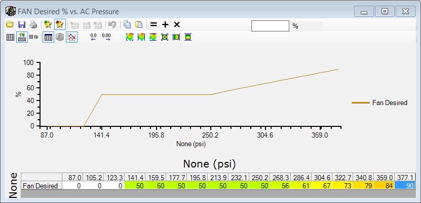
So for the alternator, what determines the duty cycle?
Andrew
This is similar to how PWM fan control works.
So for the alternator, what determines the duty cycle?
Andrew
12-14-2015, 05:34 PM
#32
Teching In
Join Date: Apr 2010
Location: Rhode Island
Posts: 18
Likes: 0
Received 0 Likes
on
0 Posts
From my understanding if you want your PCM to control your alternator you'll need one that originally has the 2 pin plug to control the DR44G alternator. If you do not then there is no way to my knowledge to be able to control a 2 pin alternator without the use of a controller of some kind (like what I just built with the arduino).
I'm wondering if the GEN IND wire can be spliced, maybe with a diode if needed, and send that to the dummy lamp on the dash.