
Foxbody and PSI Conversion guys


 04-17-2012, 09:41 PM
#23
Staging Lane
Thread Starter
iTrader: (1)

Join Date: Sep 2011
Location: Cleveland
Posts: 60
Likes: 0
Received 0 Likes
on
0 Posts
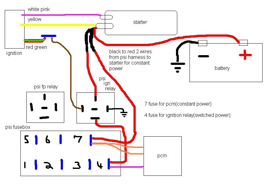
Ok I am confused. Seems that other guys just run the white/pink wire to the starter solenoid, and yellow one to starter, along with positive batter, and then in my case the 2 power wires for psi harness, which go to power the pcm, and the ignition relay.
So why is there an ignition relay on the psi harness? It does not say anything about adding another wire to this relay for the starter solenoid.
So brown wire will just run to a fuse where the other side is attached to the ignition switch that has power in the on position, like the red/green wire that used to power eec relay, ign coil, and tfi?
Sorry to keep asking questions I am just trying to make this very very clear.
I drew up another diagram to make it easier to see how everything goes, or how I think it should go.


 ^^^^^^ Fantastic
  02-13-2014, 08:41 AM
#30
Ok I am confused. Seems that other guys just run the white/pink wire to the starter solenoid, and yellow one to starter, along with positive batter, and then in my case the 2 power wires for psi harness, which go to power the pcm, and the ignition relay.
So why is there an ignition relay on the psi harness? It does not say anything about adding another wire to this relay for the starter solenoid.
So brown wire will just run to a fuse where the other side is attached to the ignition switch that has power in the on position, like the red/green wire that used to power eec relay, ign coil, and tfi?
Sorry to keep asking questions I am just trying to make this very very clear.
I drew up another diagram to make it easier to see how everything goes, or how I think it should go.
So why is there an ignition relay on the psi harness? It does not say anything about adding another wire to this relay for the starter solenoid.
So brown wire will just run to a fuse where the other side is attached to the ignition switch that has power in the on position, like the red/green wire that used to power eec relay, ign coil, and tfi?
Sorry to keep asking questions I am just trying to make this very very clear.
I drew up another diagram to make it easier to see how everything goes, or how I think it should go.
Thanks man
