

88 Fiero Formula LS4/F40 6 speed swap
 05-08-2022 | 06:51 PM
#441

Thread Starter

Joined: Feb 2010
Posts: 835
Likes: 221
From: Champaign, IL
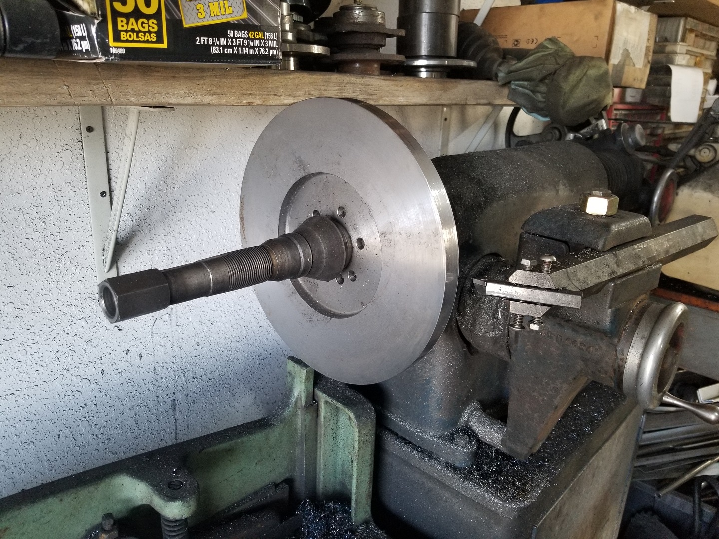
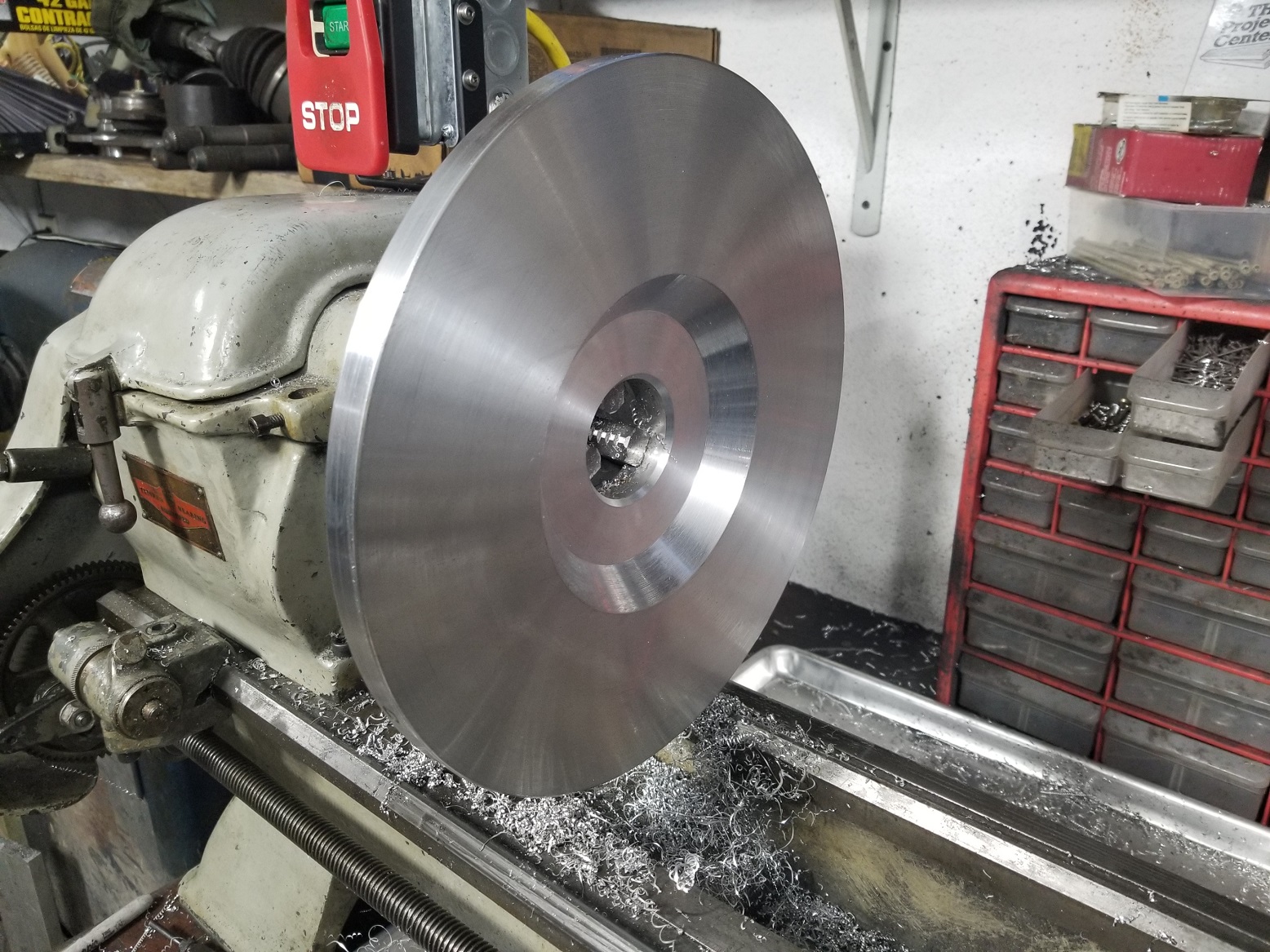
I have been working on adapting an off-the-shelf twin disc clutch to the LS4/F40 and to the point I need to actually check the depth and clearance to the differential bulge in the bellhousing. It will require some modifications to my existing aluminum flywheel, but I don't want to modify it until I know it fits... So I pulled the billet steel 168 tooth LS1 flywheel out from under the work bench and turned it down on my brake lathe.
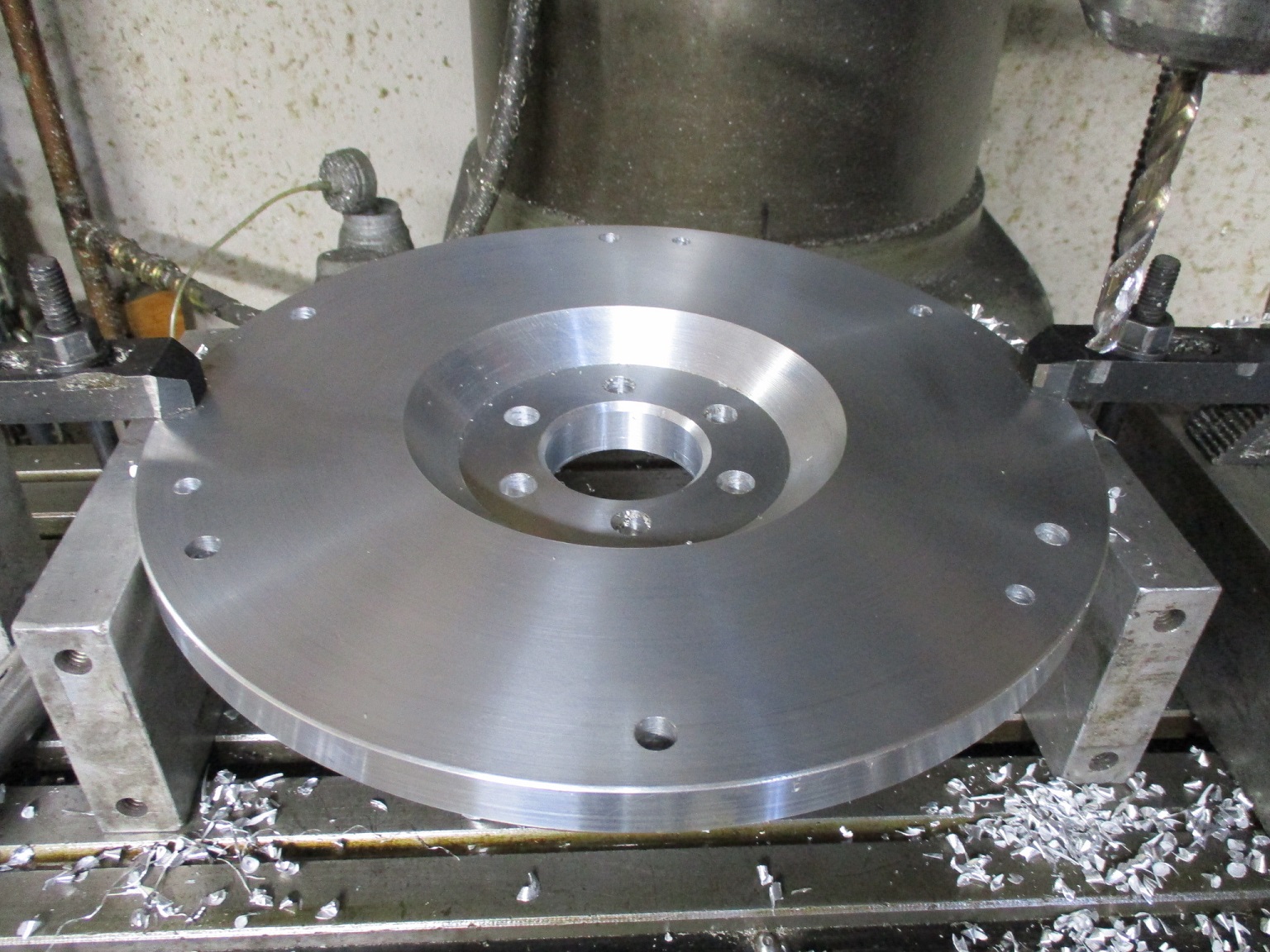
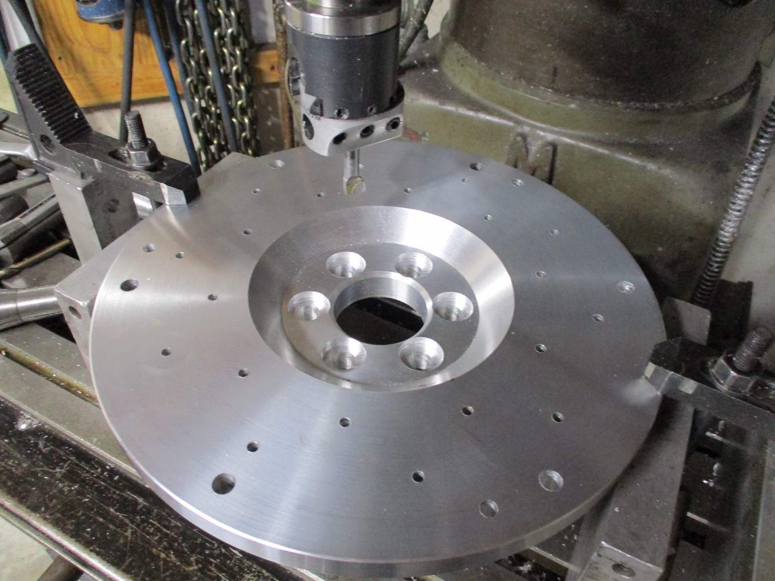
It is now the same OD as my aluminum flywheel and a smaller OD than all the prior pressure plate bolt patterns. The next step is to drill the pressure plate bolt pattern.
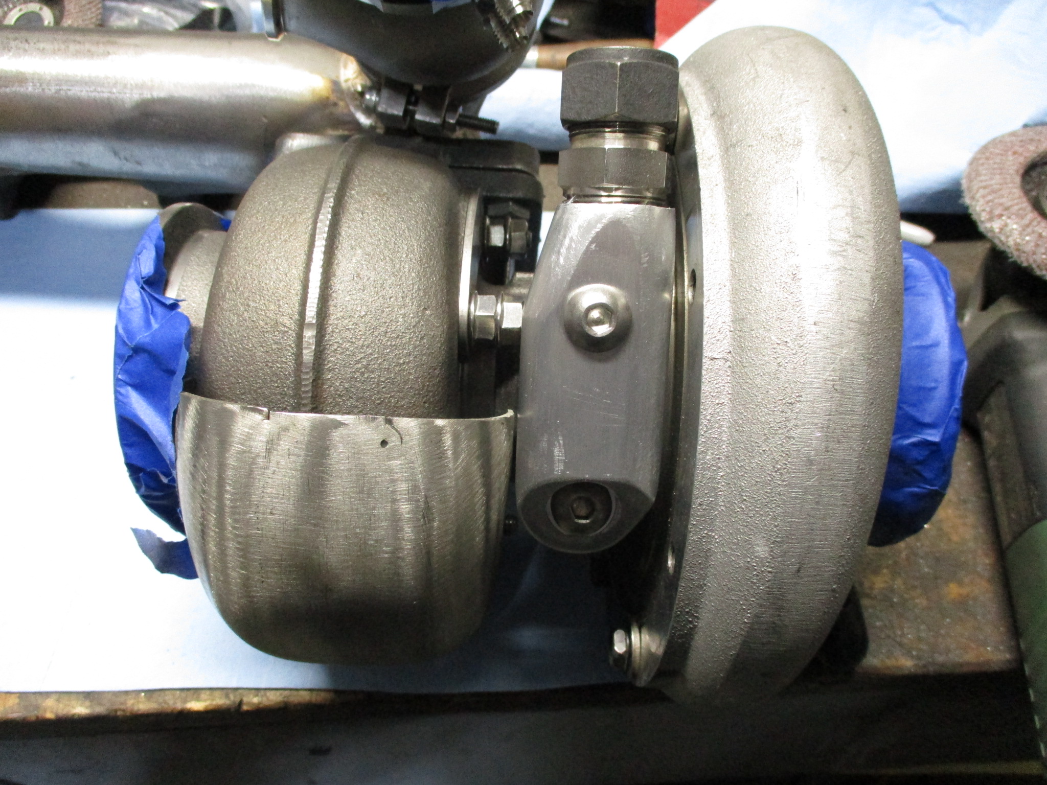
I also started working to finalize the exhaust discharge from the wastegate. Disconnected the wastegate muffler to move it closer to the wastegate and make it parallel to the floor as well as to the muffler. Still pondering if I will connect it to the full exhaust of just run it down and dump it at the bottom of the cradle. I need to get some more 2" 16ga stainless mandrel bends.
It is now the same OD as my aluminum flywheel and a smaller OD than all the prior pressure plate bolt patterns. The next step is to drill the pressure plate bolt pattern.
I also started working to finalize the exhaust discharge from the wastegate. Disconnected the wastegate muffler to move it closer to the wastegate and make it parallel to the floor as well as to the muffler. Still pondering if I will connect it to the full exhaust of just run it down and dump it at the bottom of the cradle. I need to get some more 2" 16ga stainless mandrel bends.
05-15-2022 | 03:08 PM
#442
Thread Starter
Joined: Feb 2010
Posts: 835
Likes: 221
From: Champaign, IL
Only had about 1/2 day to work on the swap this weekend so focused on the cold side and waste gate plumbing.
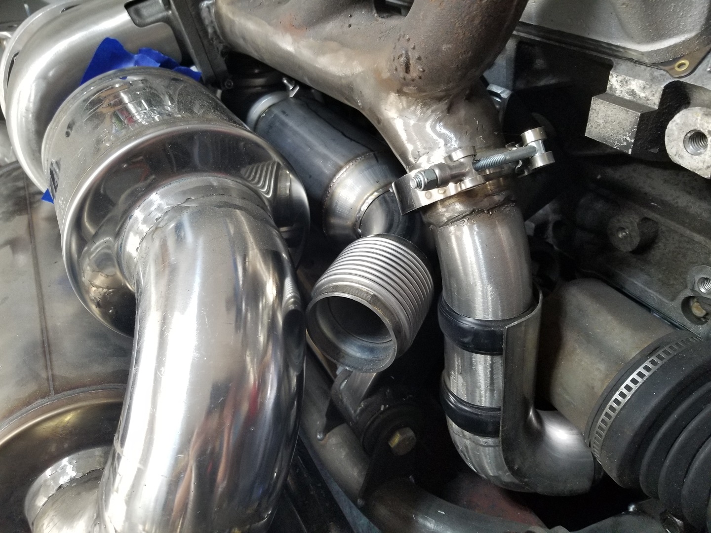
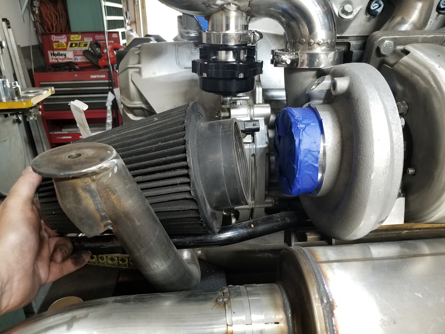
Removed about 2" of the 2 1/2" tube before the transition to 4" and added about 2" more of the 4" diameter tube after the transition. The longer this section of tube is before the bend the happier the LS7 MAF will be. Also mounted the 50mm blowoff valve and figured out the rough placement for the air filter.
Finished mocking up the wastegate exhaust dump. I decided to just dump it under the cradle vs. routing it into the main exhaust.
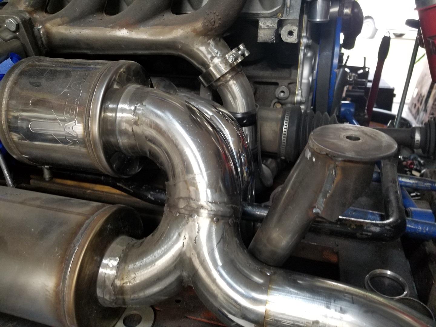
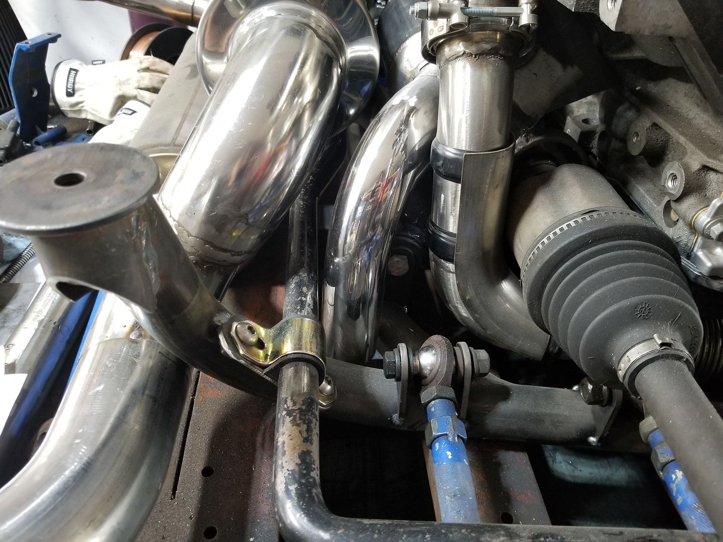
Still need to fit the resonator tube, fabricate all the support brackets for the exhaust, finish up the work with the heat shields for the hot side then lots of finish welding on the exhaust...
Removed about 2" of the 2 1/2" tube before the transition to 4" and added about 2" more of the 4" diameter tube after the transition. The longer this section of tube is before the bend the happier the LS7 MAF will be. Also mounted the 50mm blowoff valve and figured out the rough placement for the air filter.
Finished mocking up the wastegate exhaust dump. I decided to just dump it under the cradle vs. routing it into the main exhaust.
Still need to fit the resonator tube, fabricate all the support brackets for the exhaust, finish up the work with the heat shields for the hot side then lots of finish welding on the exhaust...
The following 2 users liked this post by fieroguru:
LS1-IROC (05-16-2022), Michael Yount (05-15-2022)

The following 2 users liked this post by ryeguy2006a:
fieroguru (11-27-2022), Project GatTagO (05-16-2022)


 07-03-2022 | 07:51 AM
#446
Thread Starter
Joined: Feb 2010
Posts: 835
Likes: 221
From: Champaign, IL
Started working on the more tedious portions of the turbo setup - lines and sensors.
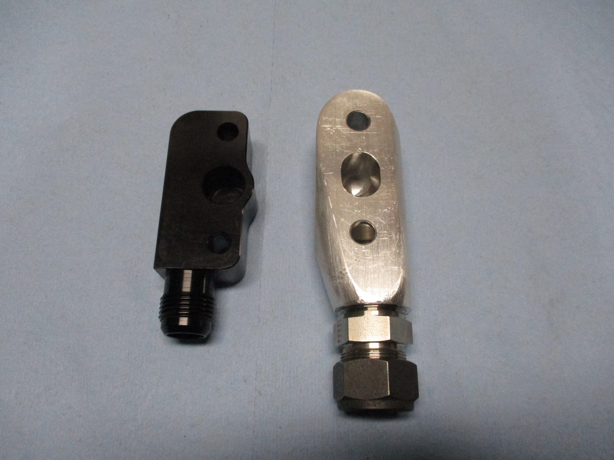
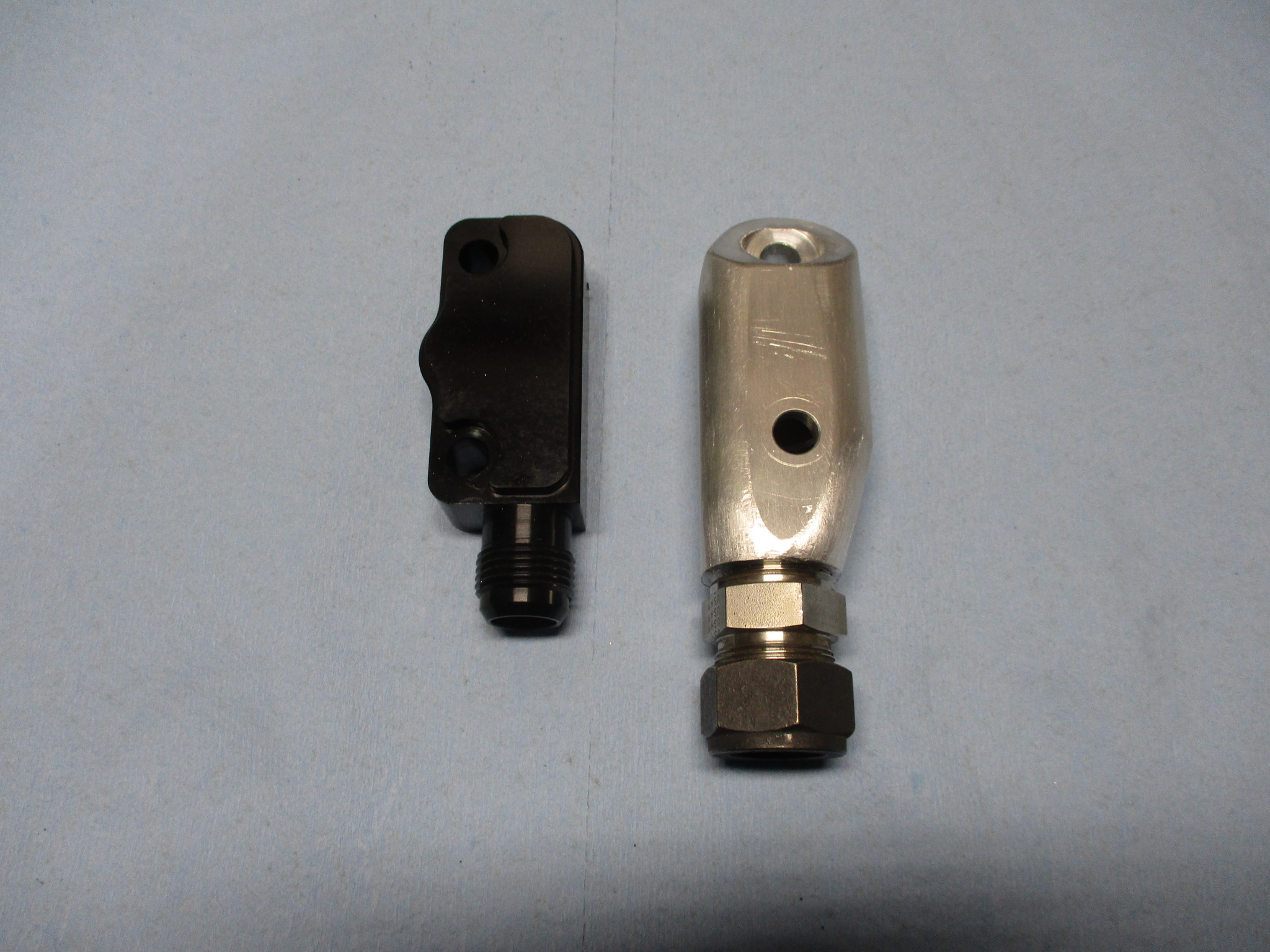
For the oil drain, I had picked up some off the shelf fittings to try, but they interfere with the heat shield and the internal passages are smaller... so I spend some time making the original oil drain housing look a little less blocky.
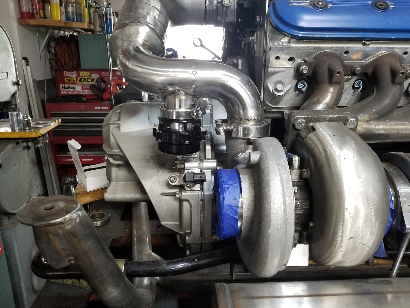
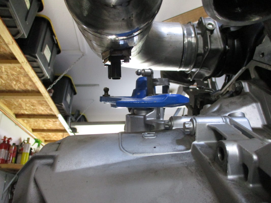
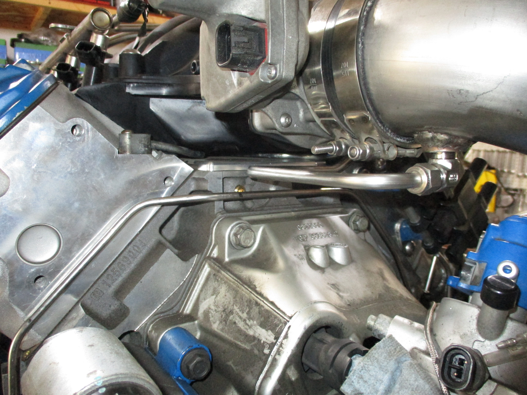
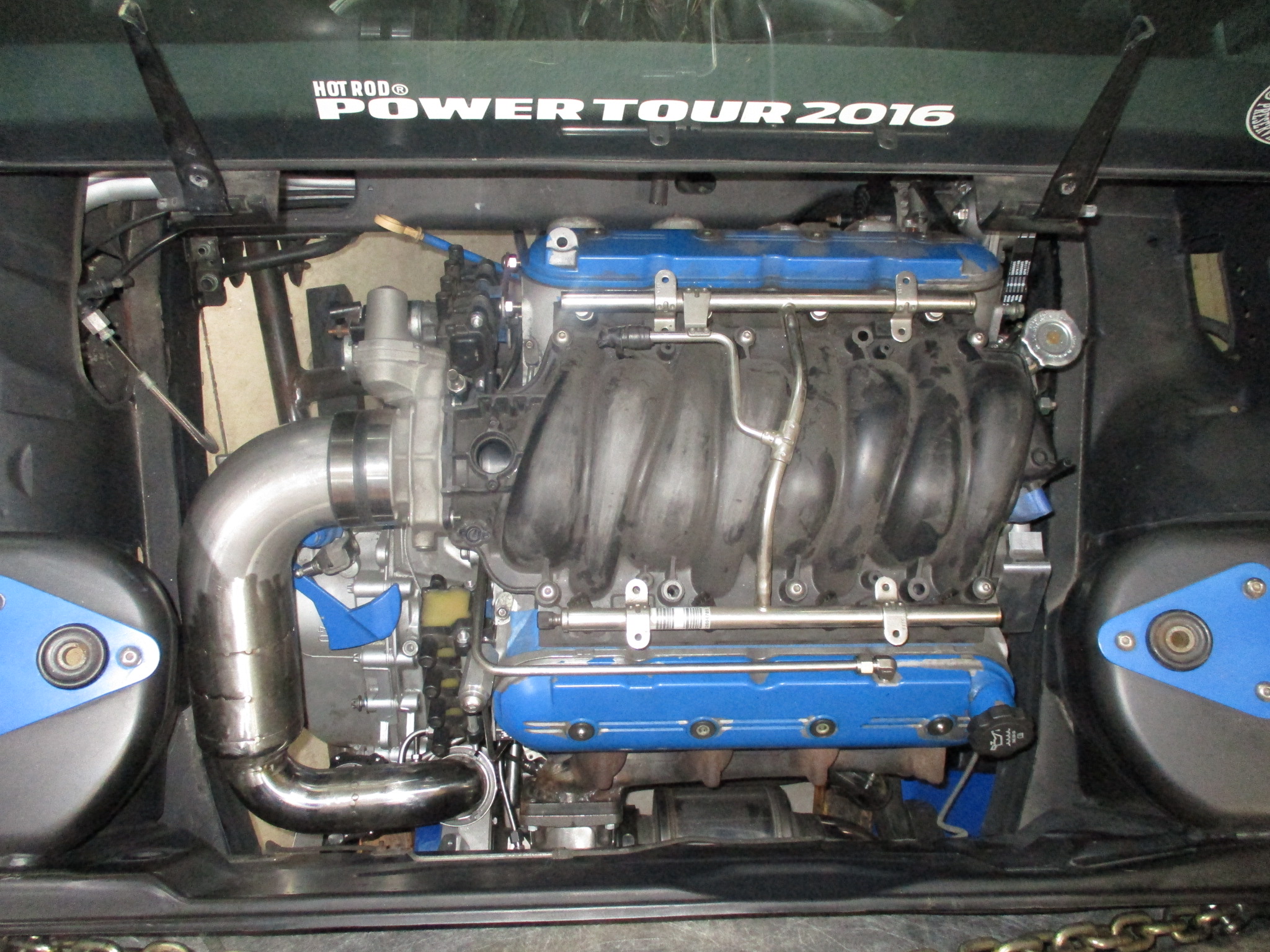
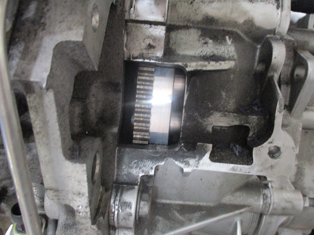
Locked down the MAF location. It is about 1" past the honeycomb insert and the connector harness will clear the range of motion of the shifter arm. Once I got it mocked up, I noticed that the intake tube is parallel with the shifter arm... didn't plan it that way, but a very nice coincidence!
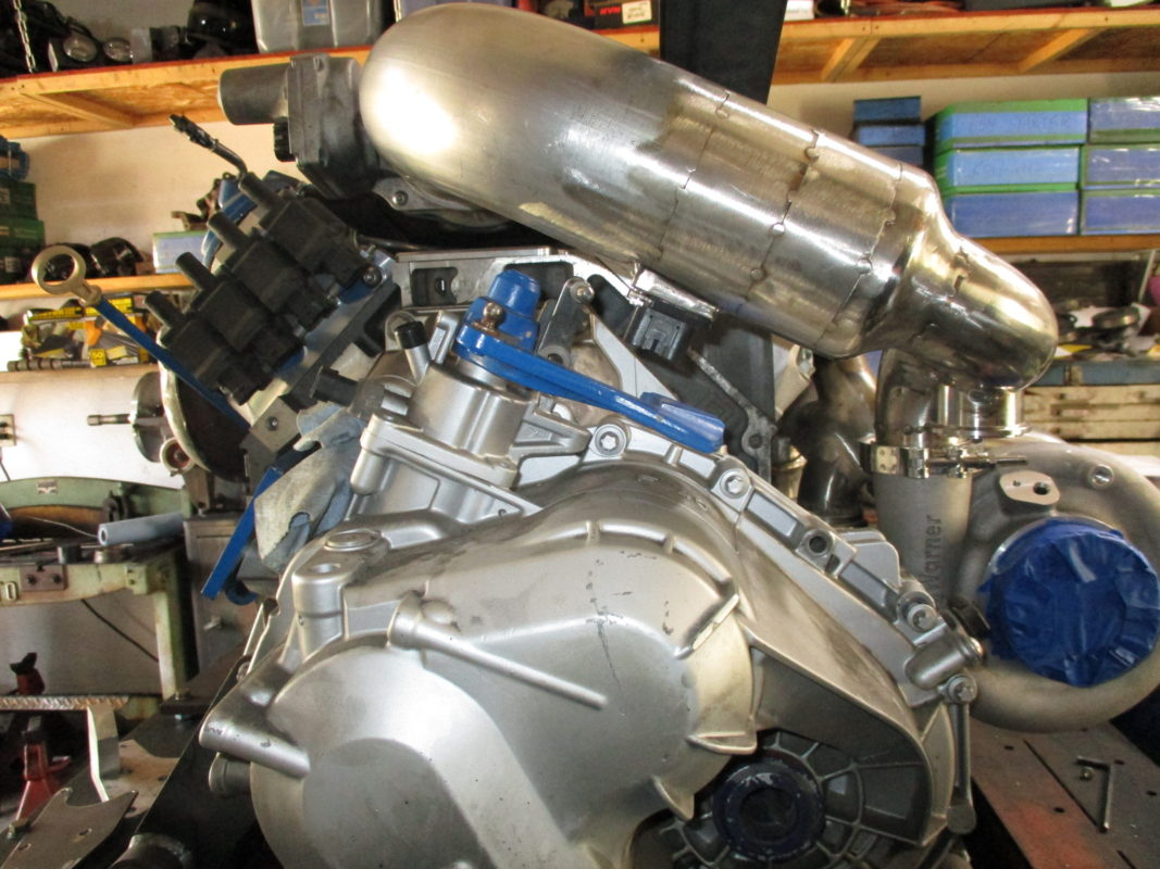
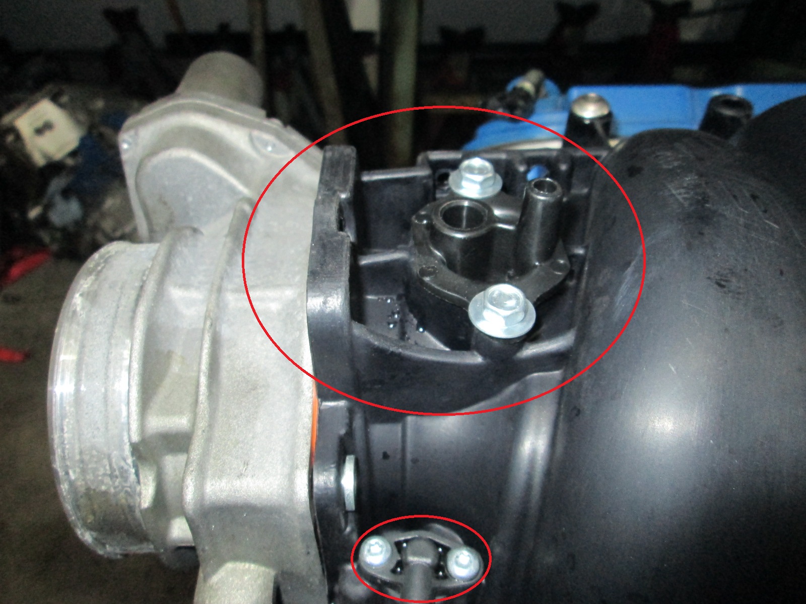
Oil Feed:
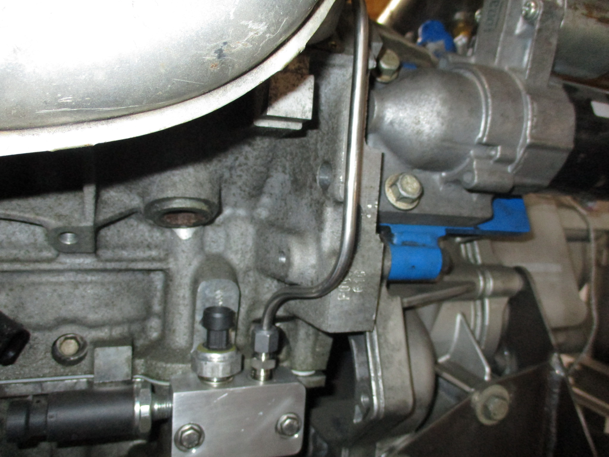
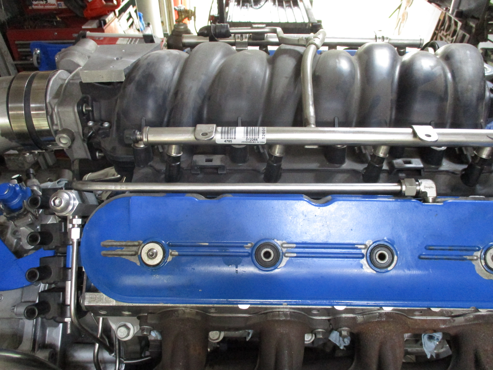
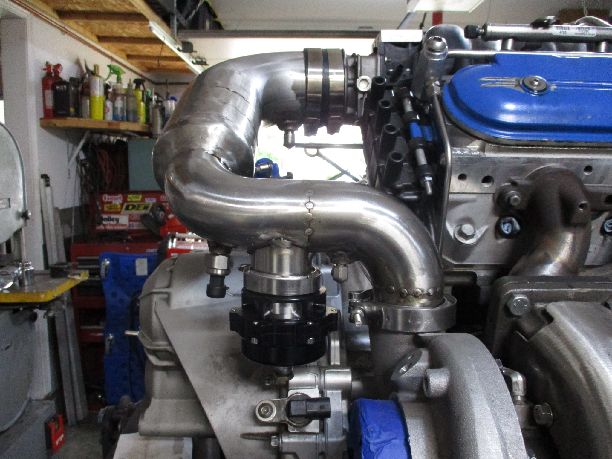
Here you can see the oil feed line going over the bellhousing. Also visible is the PCV hard line connection to the air intake tube (filtered & metered air - no check valve installed yet)
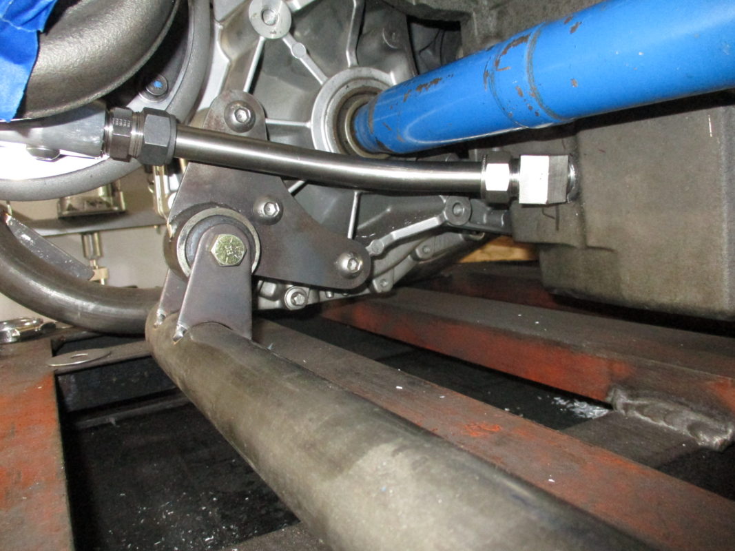
PCV hard line to the valve cover. Also visible is the new adjustable boost **** (button head). I purchased a small cheap blue one but it wouldn't accept the hard lines, so I took the spring and ball from it and made a new manual boost controller from aluminum hex.
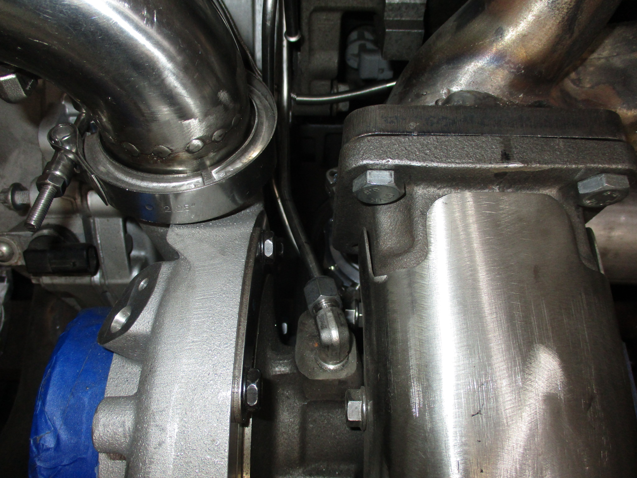
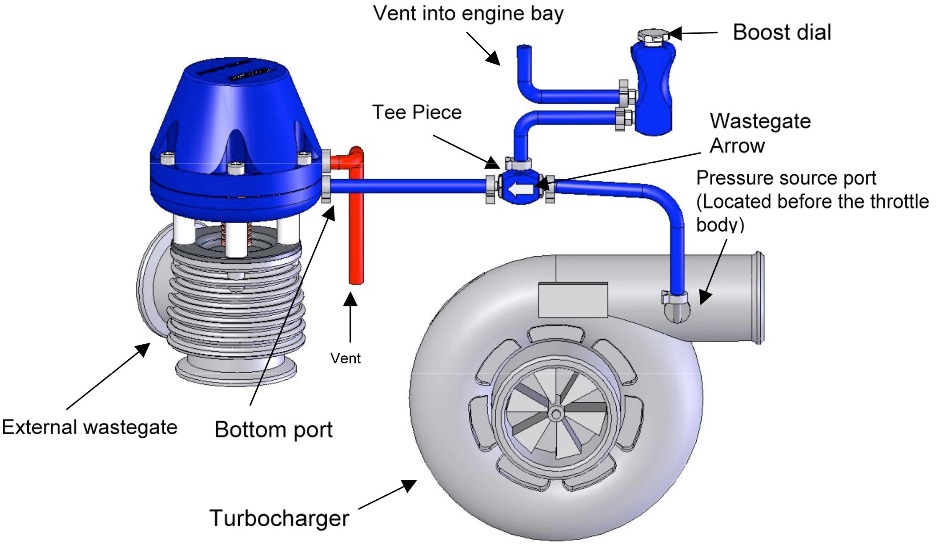
For boost control, I am going to keep it simple to start with. Manual engine bay mounted adjustable boost control valve plumbed like this:
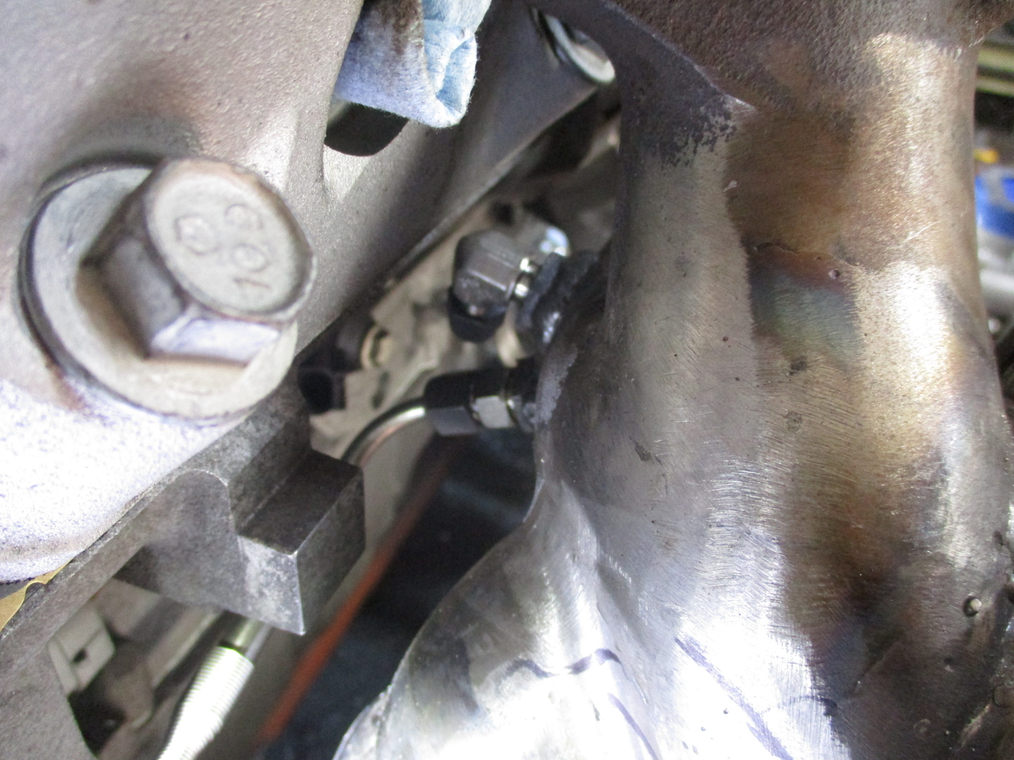
The warm side had a sensor boss (pressure), temp boss (not seen - it is downstream of MAF), and boss for the waste gate hard line.
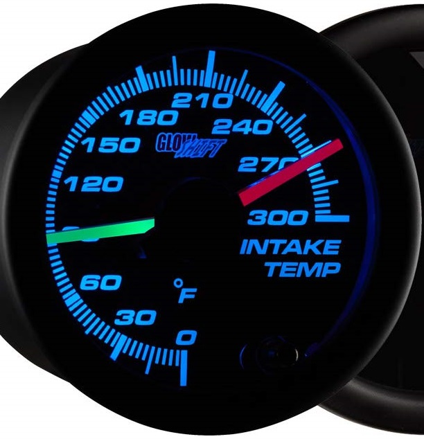
I will be using this gauge to monitor (not datalog) the pre/post turbo air temps so I can get a feel for the delta due to non-intercooled.
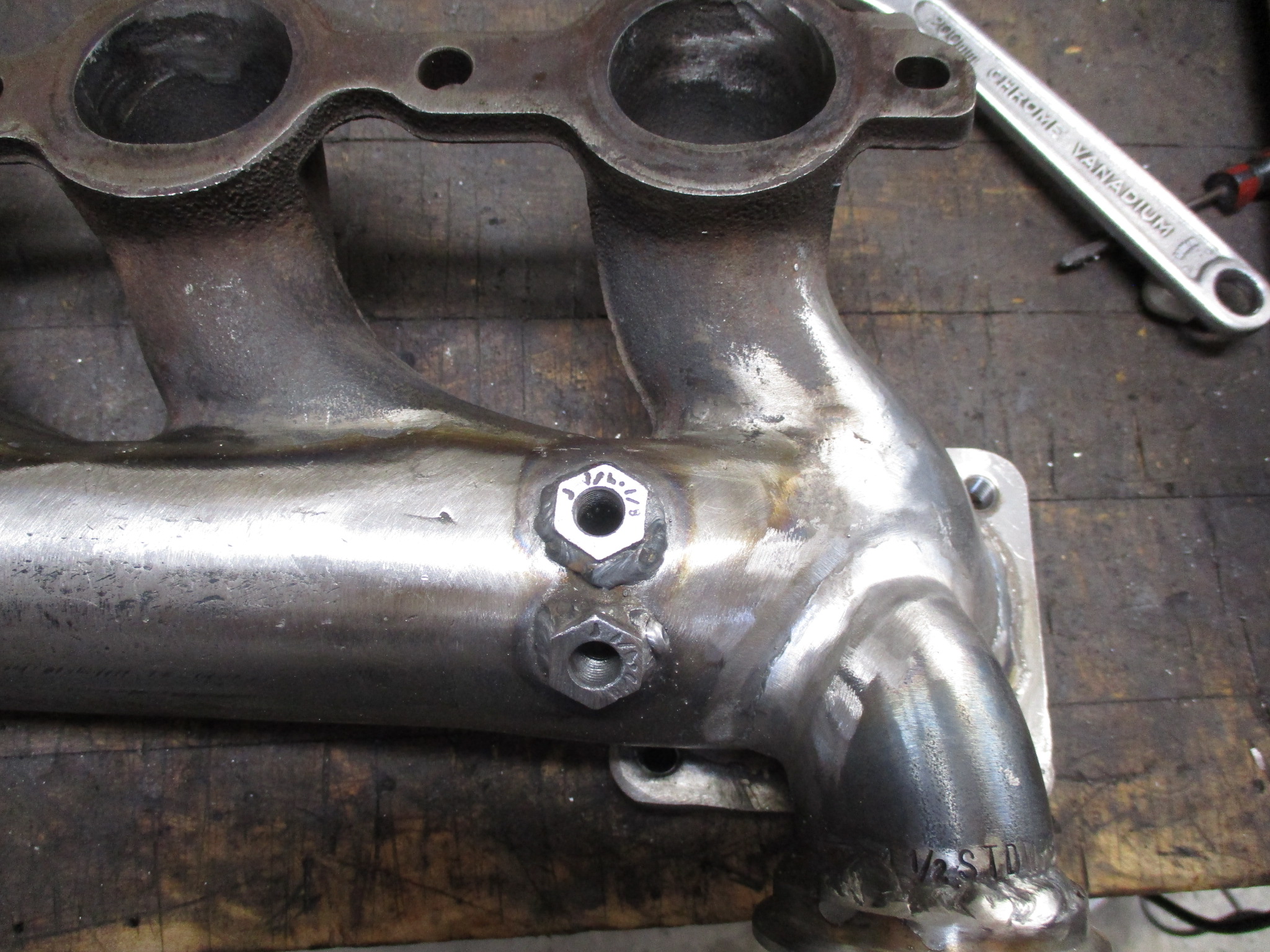
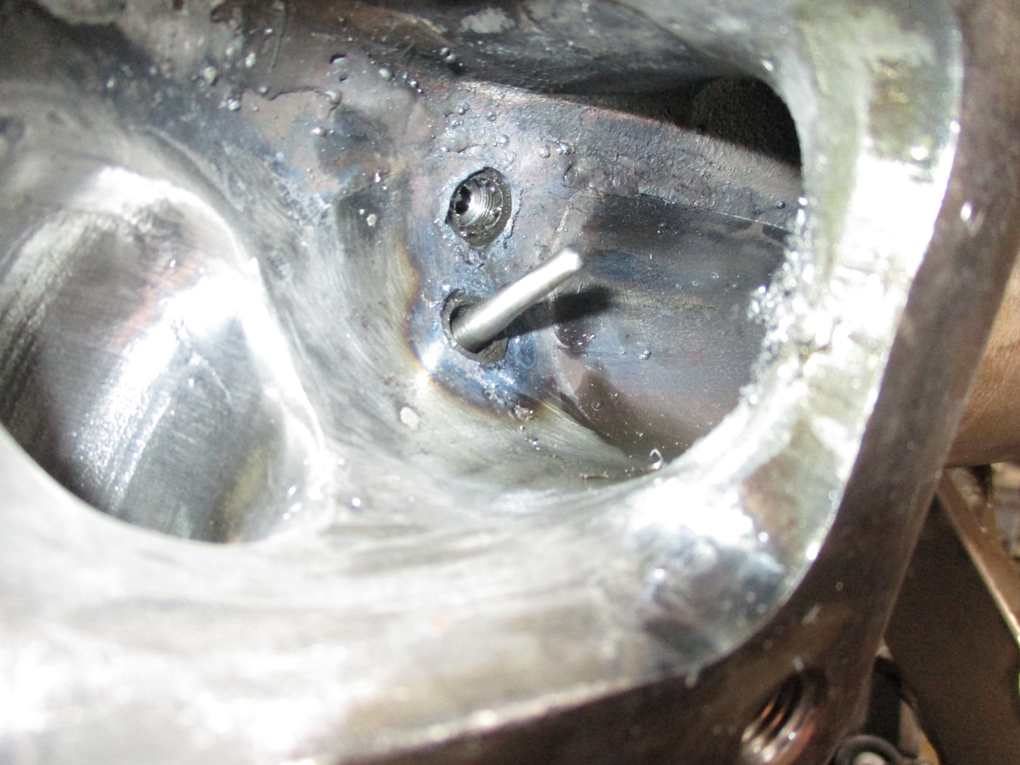
I also welded some bosses onto the turbo manifold back side for the EGT sensor and a hard line to a pressure sensor.
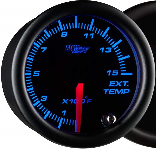
The EGT will be monitored (not logged) via this gauge:
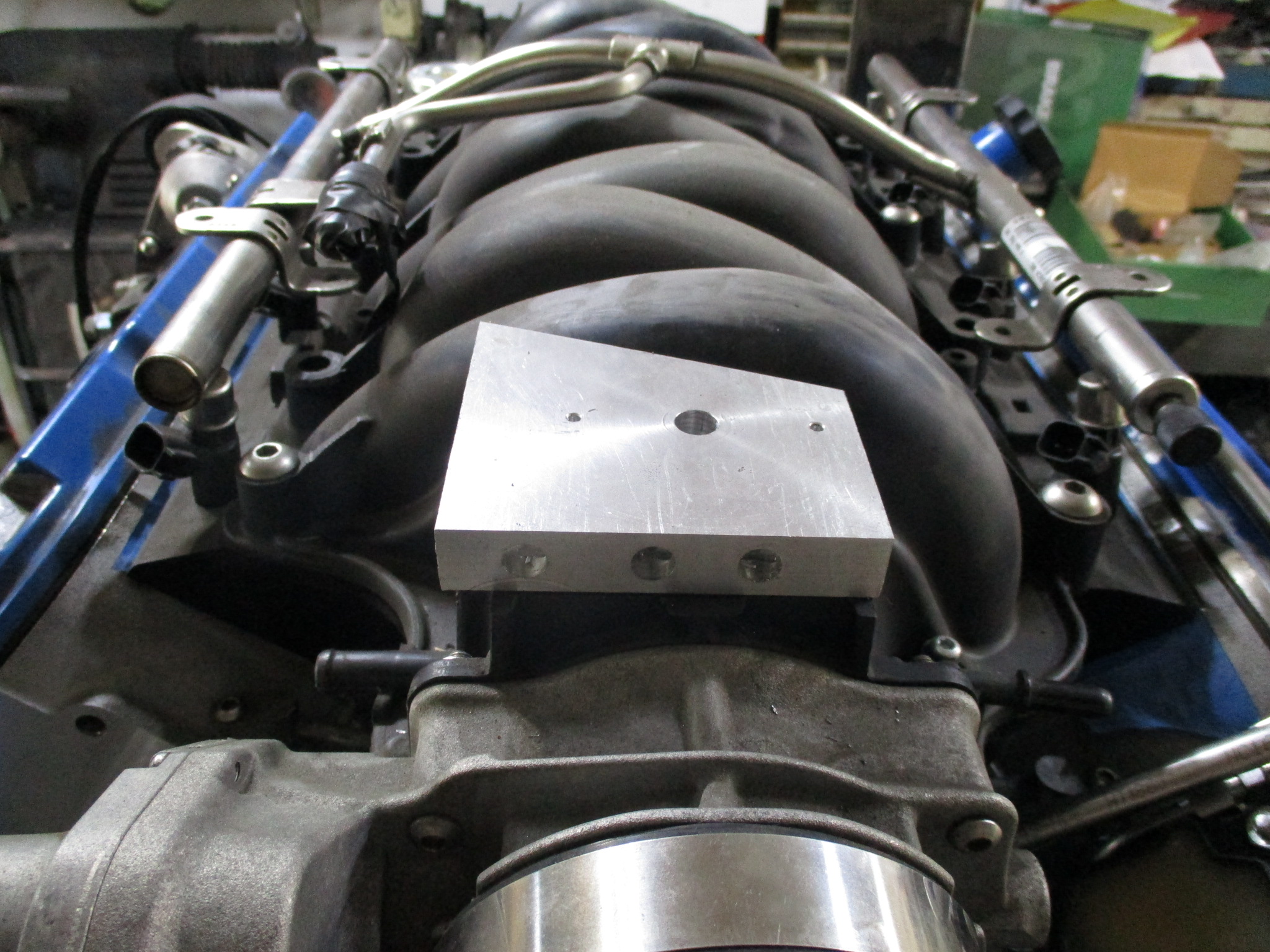
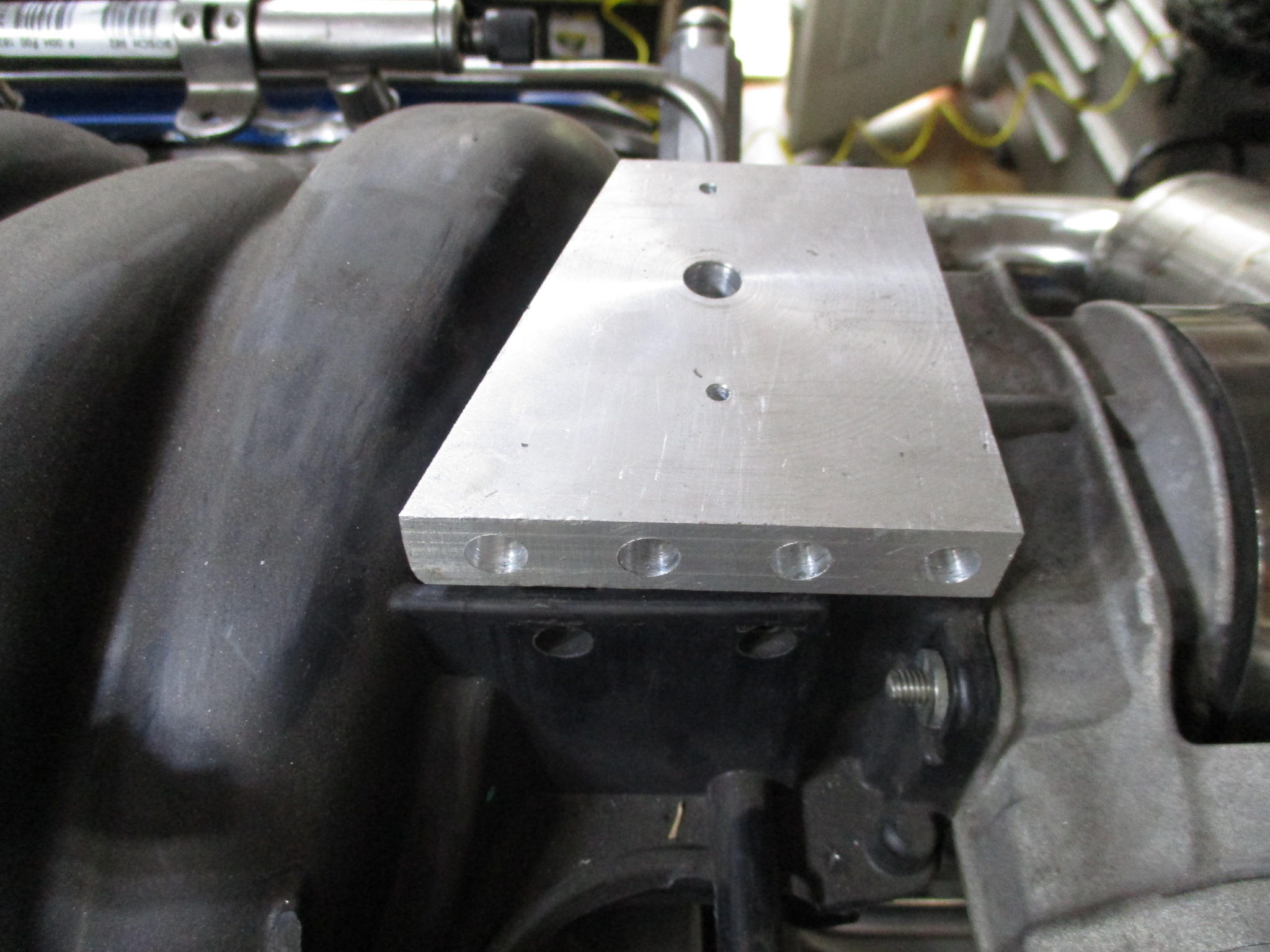
The intake manifold also has an ugly hole right behind throttle body and there are several needed reference lines from the manifold (BOV, PCV (dirty) MAF, vac tank for cutout). To address everything, I started making vacuum/boost manifold that will cover the hole in the intake as well. It has a machined boss on the bottom side with an o-ring seal for the intake hole.
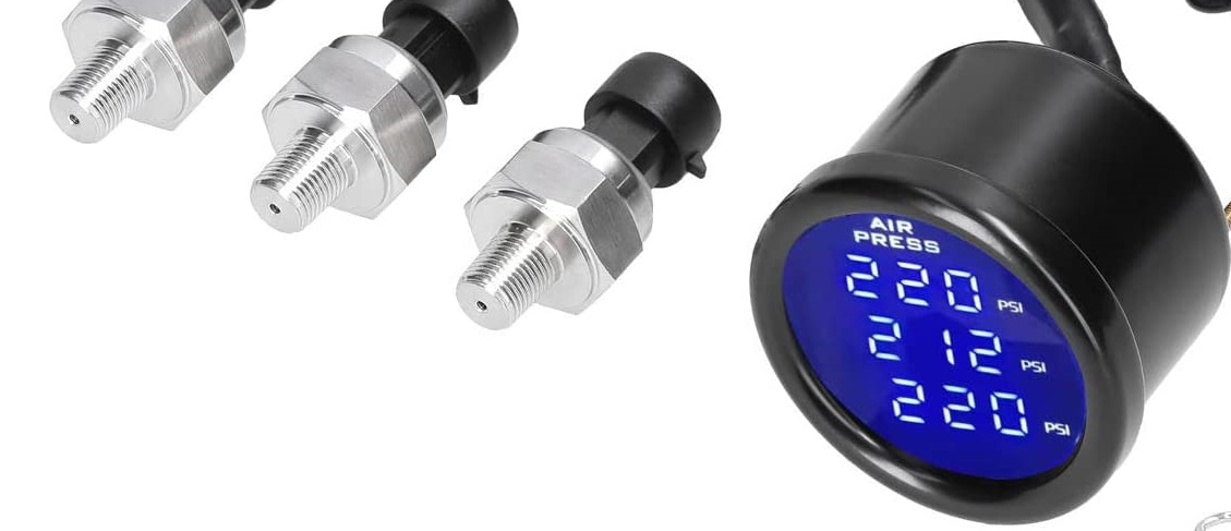
This 3 in one pressure gauge will allow me to monitor boost, pre-turbo back pressure and post turbo back pressure (cutout open/closed):
For the oil drain, I had picked up some off the shelf fittings to try, but they interfere with the heat shield and the internal passages are smaller... so I spend some time making the original oil drain housing look a little less blocky.
Locked down the MAF location. It is about 1" past the honeycomb insert and the connector harness will clear the range of motion of the shifter arm. Once I got it mocked up, I noticed that the intake tube is parallel with the shifter arm... didn't plan it that way, but a very nice coincidence!
Oil Feed:
Here you can see the oil feed line going over the bellhousing. Also visible is the PCV hard line connection to the air intake tube (filtered & metered air - no check valve installed yet)
PCV hard line to the valve cover. Also visible is the new adjustable boost **** (button head). I purchased a small cheap blue one but it wouldn't accept the hard lines, so I took the spring and ball from it and made a new manual boost controller from aluminum hex.
For boost control, I am going to keep it simple to start with. Manual engine bay mounted adjustable boost control valve plumbed like this:
The warm side had a sensor boss (pressure), temp boss (not seen - it is downstream of MAF), and boss for the waste gate hard line.
I will be using this gauge to monitor (not datalog) the pre/post turbo air temps so I can get a feel for the delta due to non-intercooled.
I also welded some bosses onto the turbo manifold back side for the EGT sensor and a hard line to a pressure sensor.
The EGT will be monitored (not logged) via this gauge:
The intake manifold also has an ugly hole right behind throttle body and there are several needed reference lines from the manifold (BOV, PCV (dirty) MAF, vac tank for cutout). To address everything, I started making vacuum/boost manifold that will cover the hole in the intake as well. It has a machined boss on the bottom side with an o-ring seal for the intake hole.
This 3 in one pressure gauge will allow me to monitor boost, pre-turbo back pressure and post turbo back pressure (cutout open/closed):

 07-03-2022 | 10:44 AM
#448
Joined: Mar 2003
Posts: 10,231
Likes: 1,519
From: The City of Fountains
Started working on the more tedious portions of the turbo setup - lines and sensors.
For the oil drain, I had picked up some off the shelf fittings to try, but they interfere with the heat shield and the internal passages are smaller... so I spend some time making the original oil drain housing look a little less blocky.
Locked down the MAF location. It is about 1" past the honeycomb insert and the connector harness will clear the range of motion of the shifter arm. Once I got it mocked up, I noticed that the intake tube is parallel with the shifter arm... didn't plan it that way, but a very nice coincidence!
Oil Feed:
Here you can see the oil feed line going over the bellhousing. Also visible is the PCV hard line connection to the air intake tube (filtered & metered air - no check valve installed yet)
PCV hard line to the valve cover. Also visible is the new adjustable boost **** (button head). I purchased a small cheap blue one but it wouldn't accept the hard lines, so I took the spring and ball from it and made a new manual boost controller from aluminum hex.
For boost control, I am going to keep it simple to start with. Manual engine bay mounted adjustable boost control valve plumbed like this:
The warm side had a sensor boss (pressure), temp boss (not seen - it is downstream of MAF), and boss for the waste gate hard line.
I will be using this gauge to monitor (not datalog) the pre/post turbo air temps so I can get a feel for the delta due to non-intercooled.
I also welded some bosses onto the turbo manifold back side for the EGT sensor and a hard line to a pressure sensor.
The EGT will be monitored (not logged) via this gauge:
The intake manifold also has an ugly hole right behind throttle body and there are several needed reference lines from the manifold (BOV, PCV (dirty) MAF, vac tank for cutout). To address everything, I started making vacuum/boost manifold that will cover the hole in the intake as well. It has a machined boss on the bottom side with an o-ring seal for the intake hole.
This 3 in one pressure gauge will allow me to monitor boost, pre-turbo back pressure and post turbo back pressure (cutout open/closed):
Andrew
07-03-2022 | 11:24 AM
#449
Thread Starter
Joined: Feb 2010
Posts: 835
Likes: 221
From: Champaign, IL
Generally speaking, I just am not a fan of aftermarket efi systems. They don't have the OEM level of R&D and reliability. Sure they have other features that OEM systems have, and do make it easier to do several things, but they are also produced in much smaller quantities and will be obsoleted as the aftermarket company pushes through newer/better systems. I already have HP tuners and do my own tuning, so there wasn't much consideration for the Holley.
Last edited by fieroguru; 07-03-2022 at 11:33 AM.
The following users liked this post:
Project GatTagO (07-03-2022)
11-26-2022 | 02:42 PM
#450
Thread Starter
Joined: Feb 2010
Posts: 835
Likes: 221
From: Champaign, IL
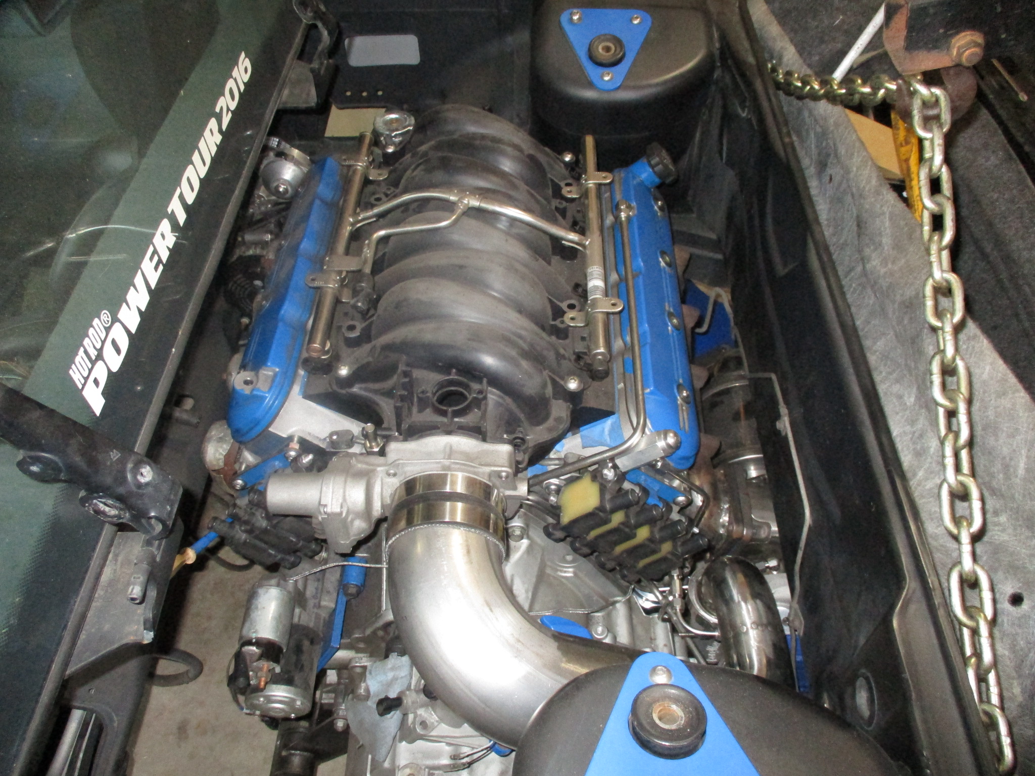
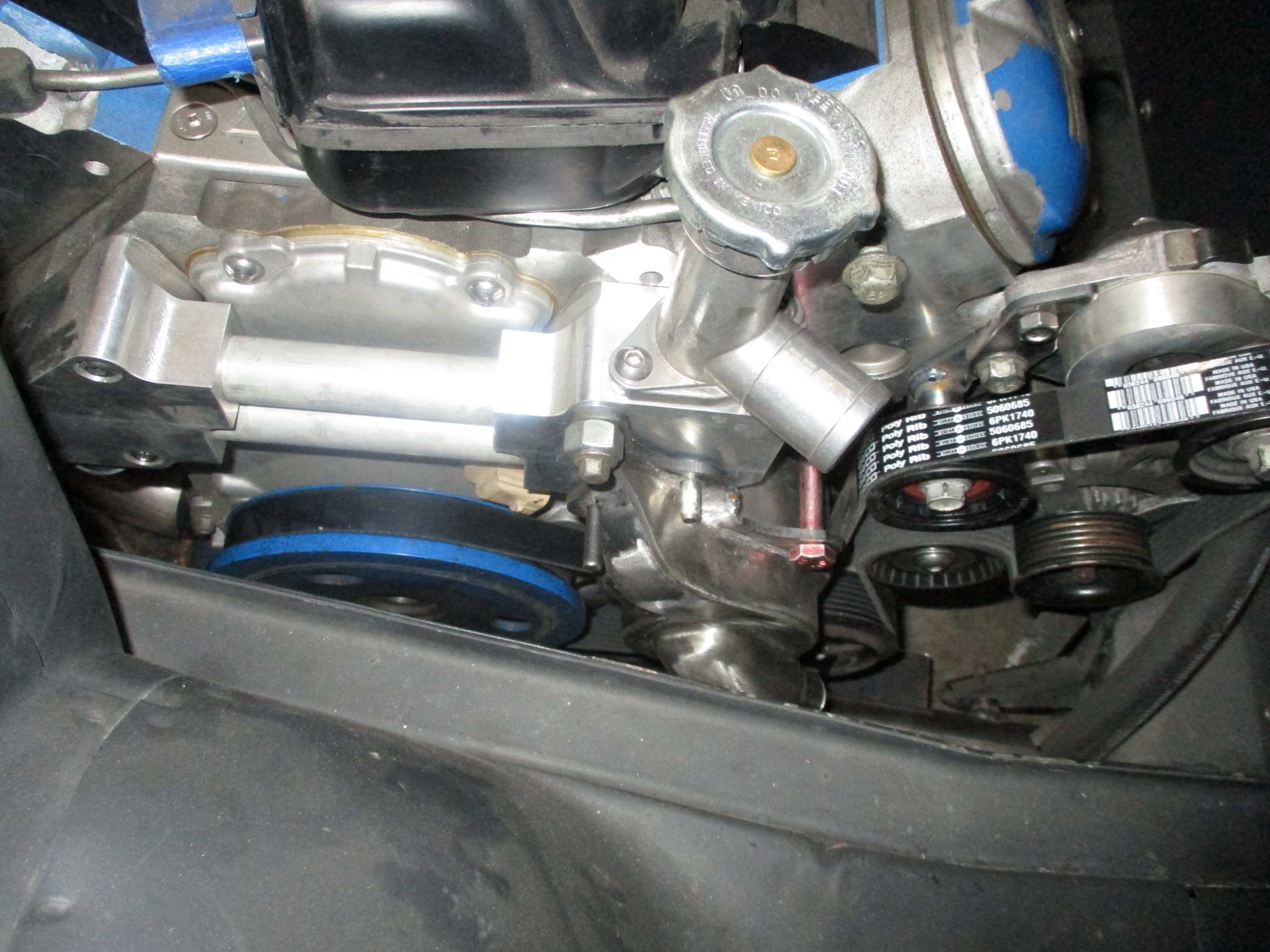
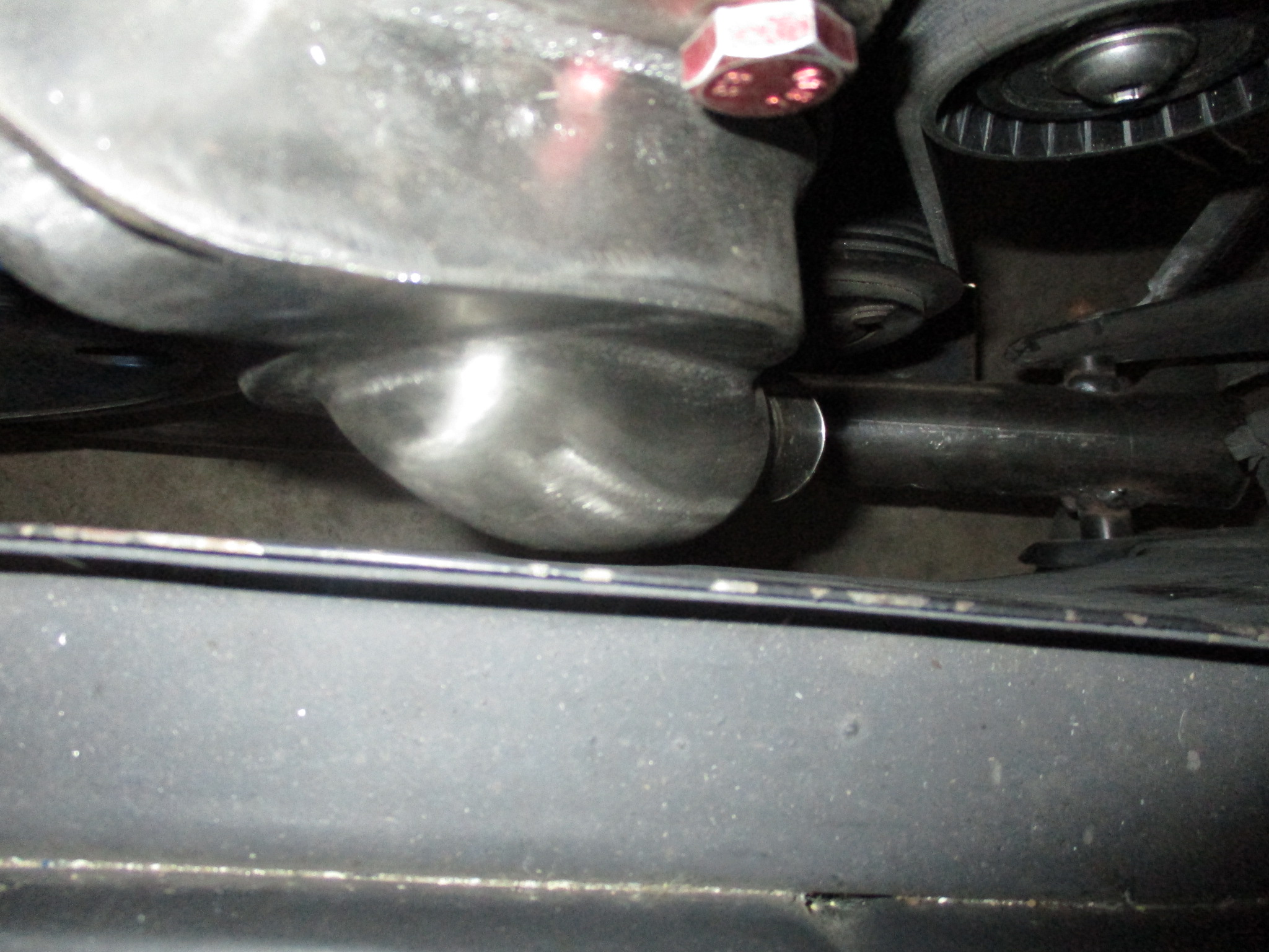
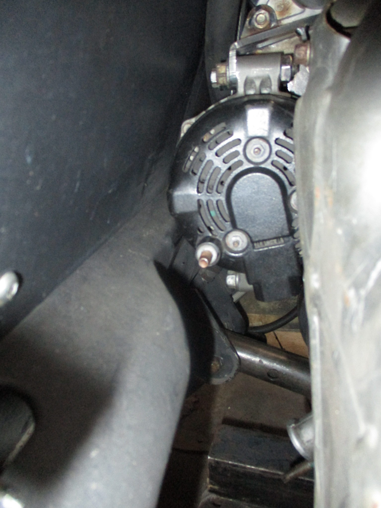
I have been slacking with updates. Did another test fit in the chassis to confirm mechanical water pump clearance to the frame rail and the alternator clears the cross support tube:
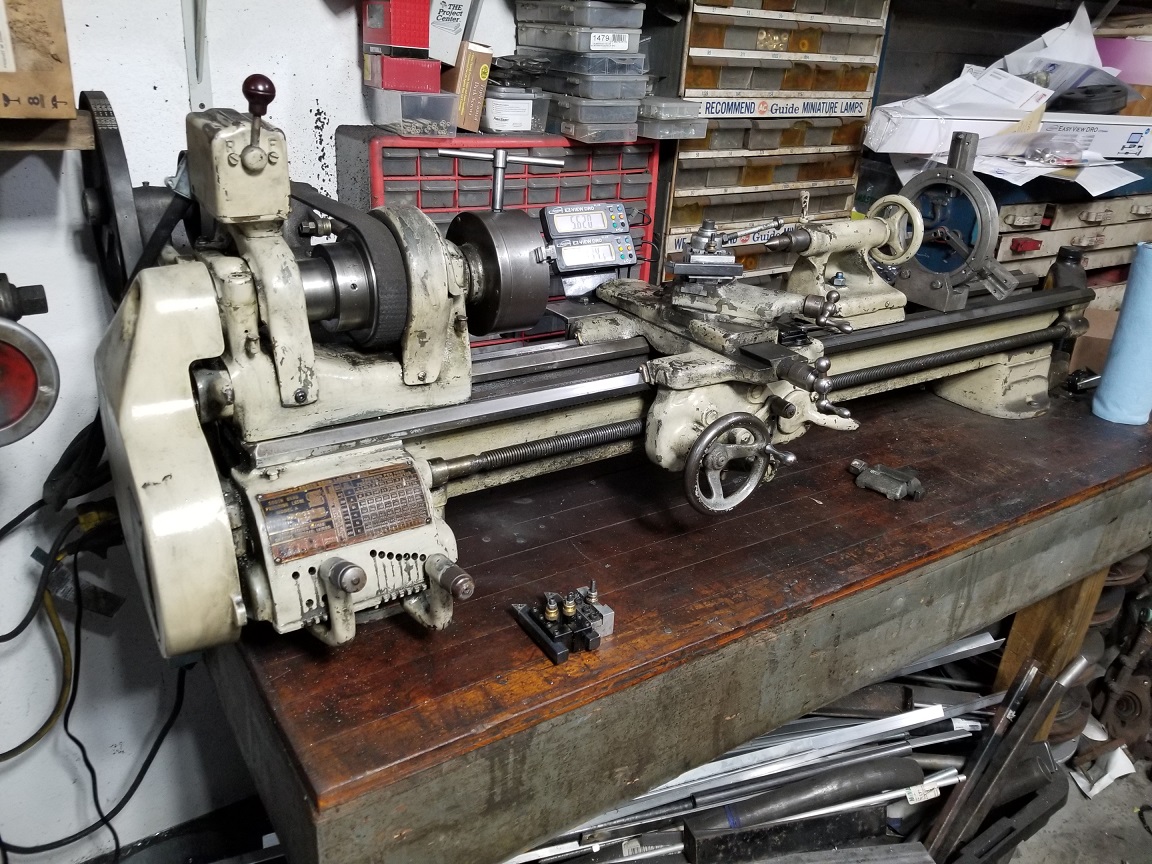
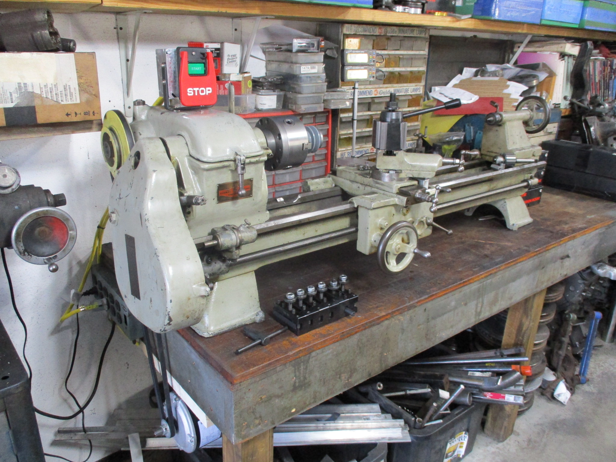
While the engine was off the work bench, I picked up a 12" Clausing Lathe sold off my Southbend 9" one. The Clausing was treated with DROs, new chuck and BXA tool holder setup. It also had the ways clearanced so that I can chuck up a LS flywheel (168 tooth ring gear knocked off).
Old Southbend:
12" Clausing:
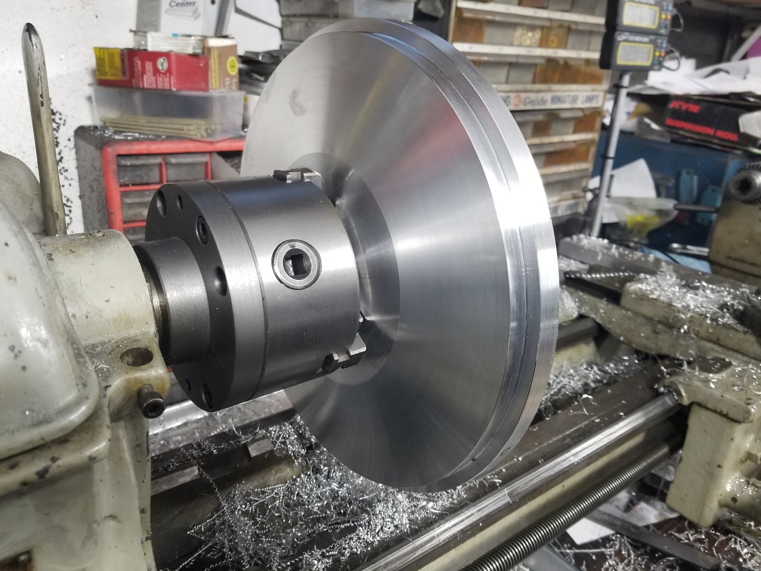
LS flywheel chucked up:
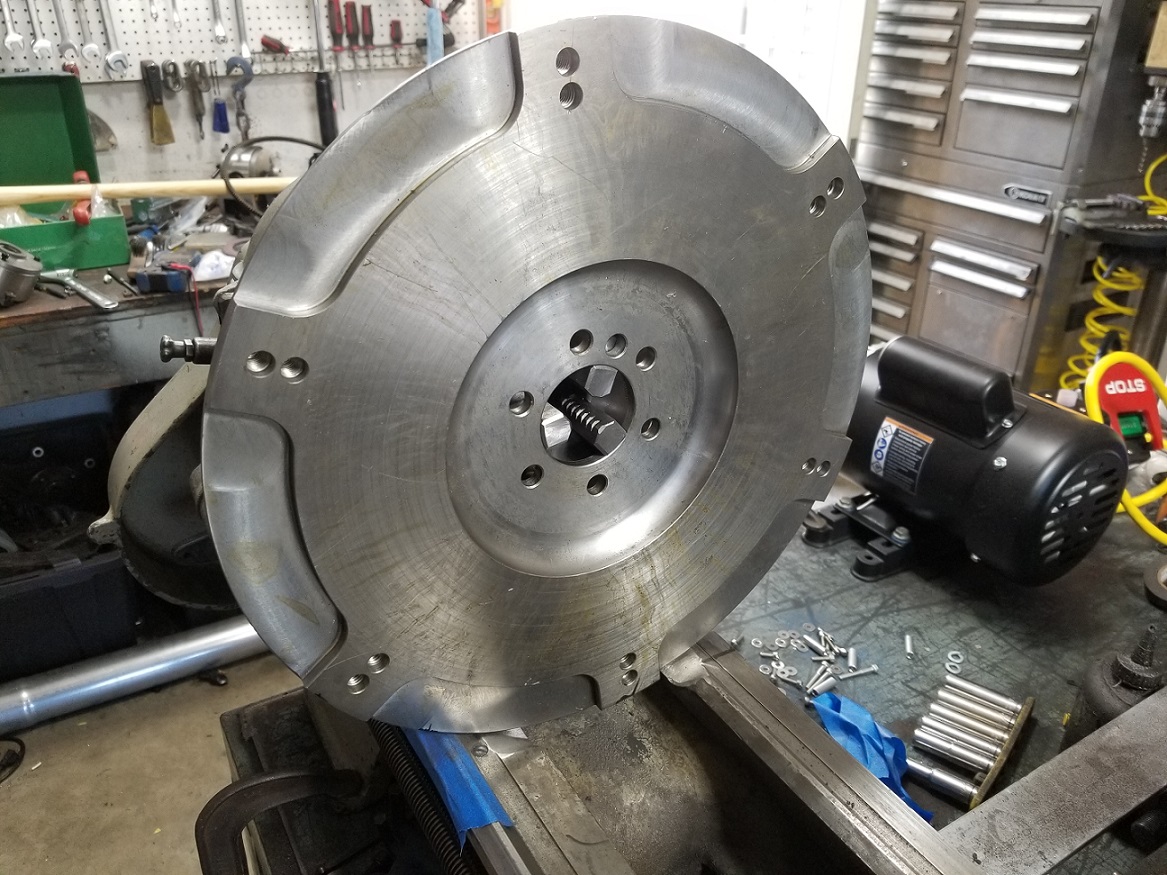
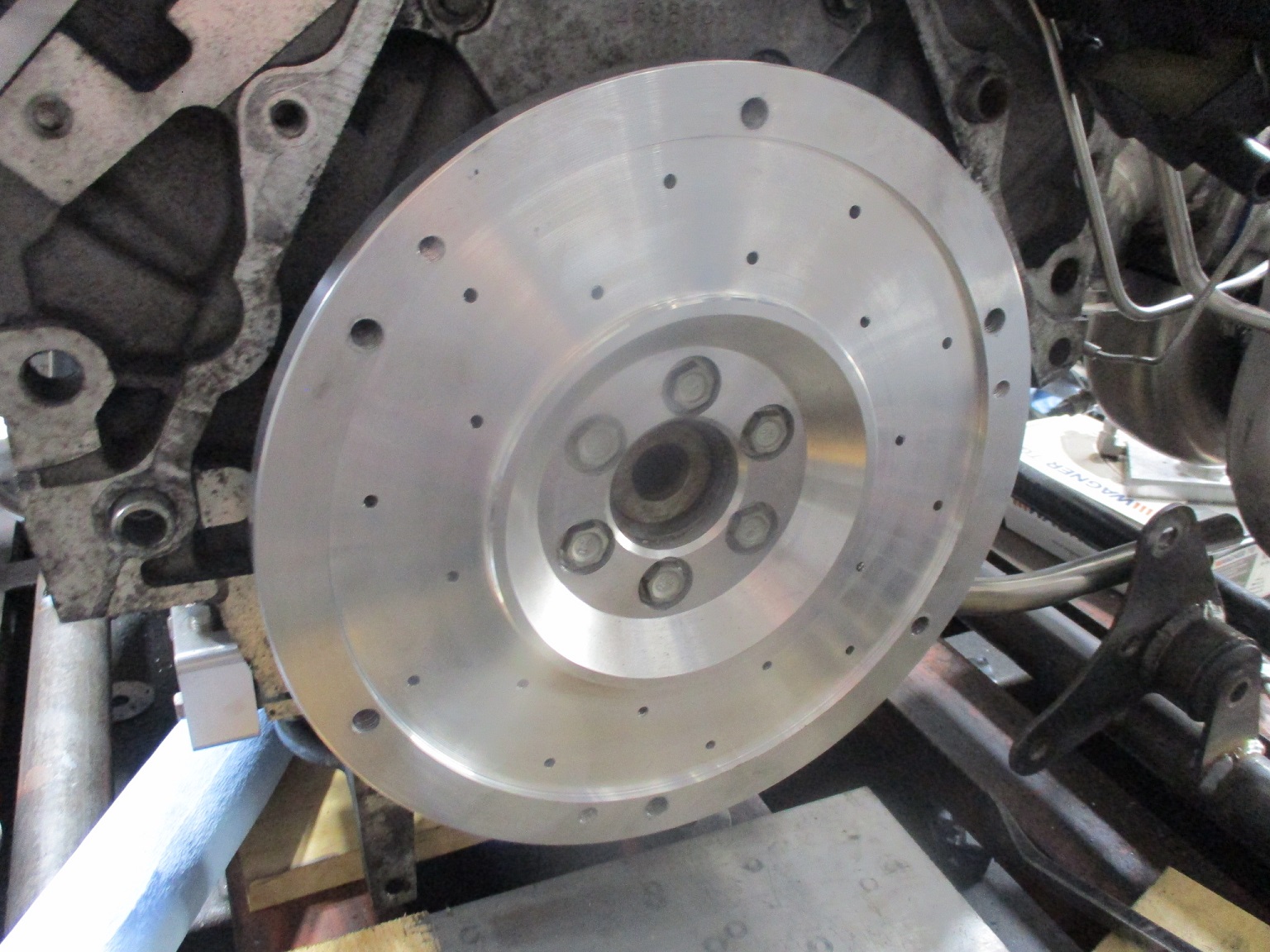
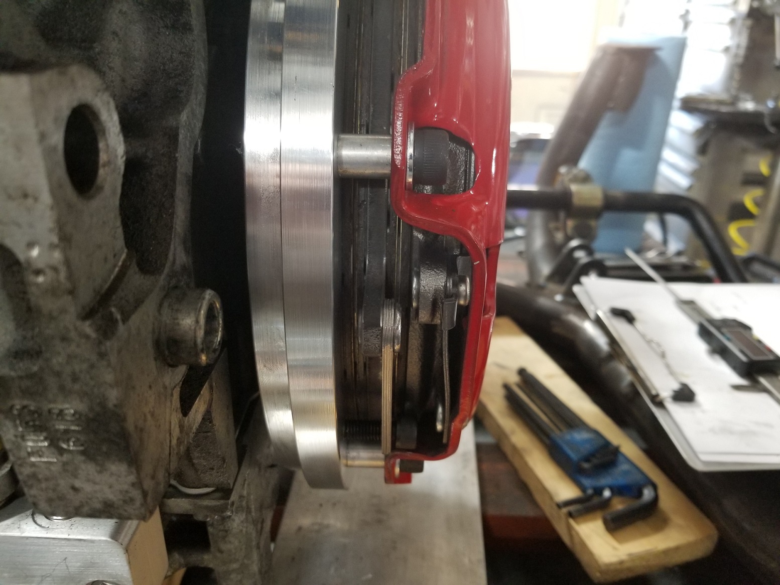
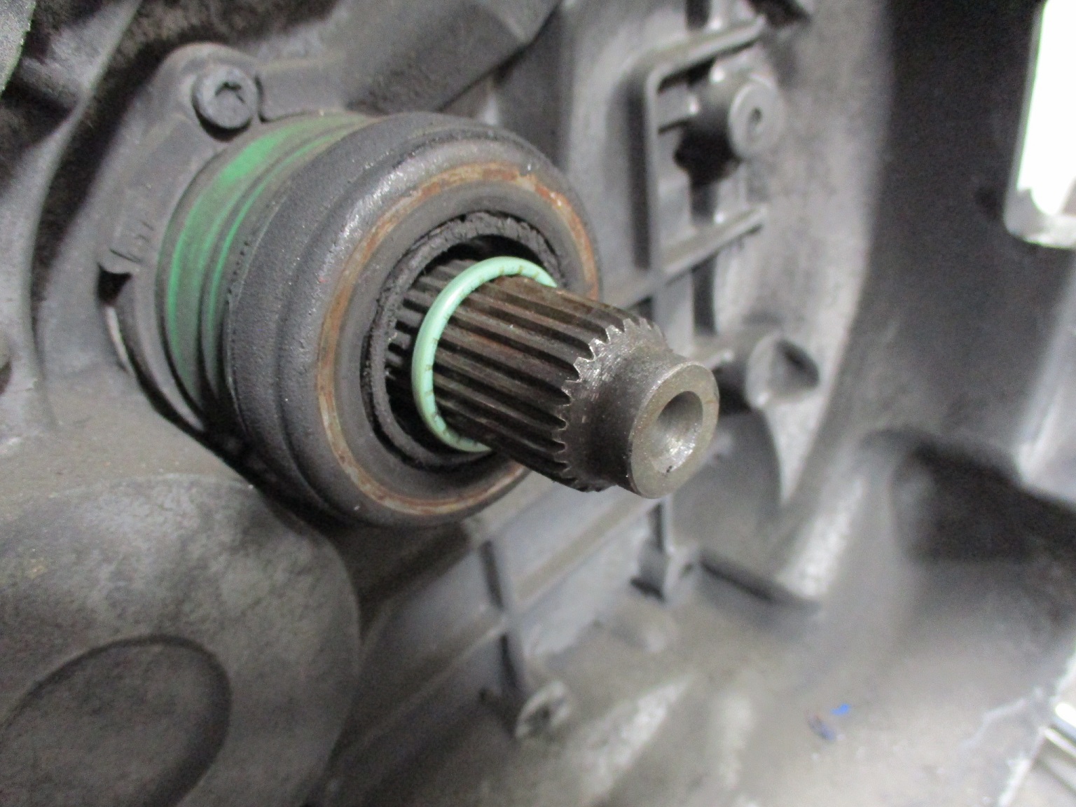
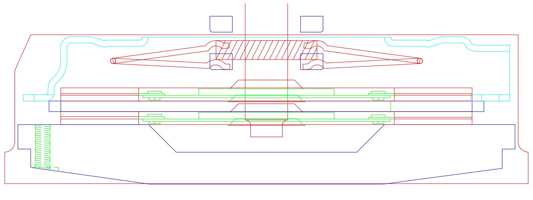
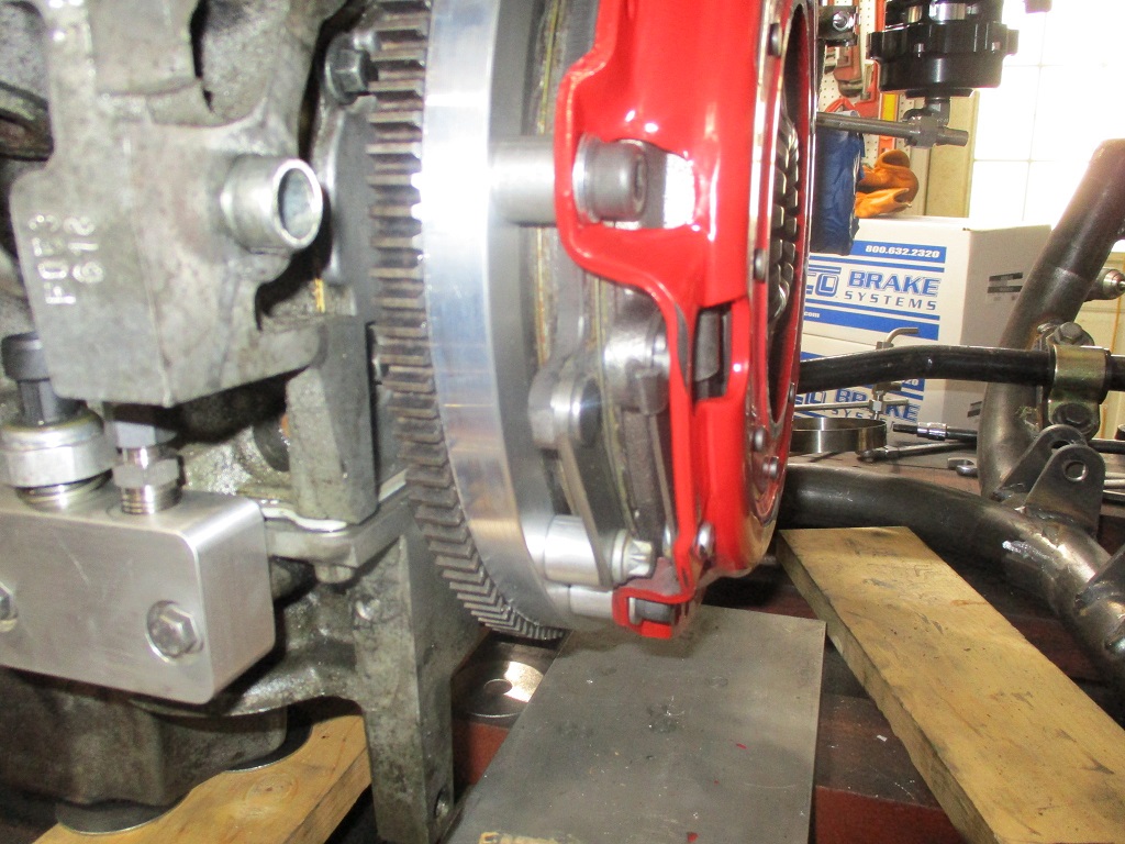
Then I started making a new aluminum flywheel for a twin disc clutch rated for 800 hp. It is a super tight fit, but with a couple of minor modifications to the pressure plate, I was able to get full spline engagement on both discs as well as adequate finger clearance for wear.
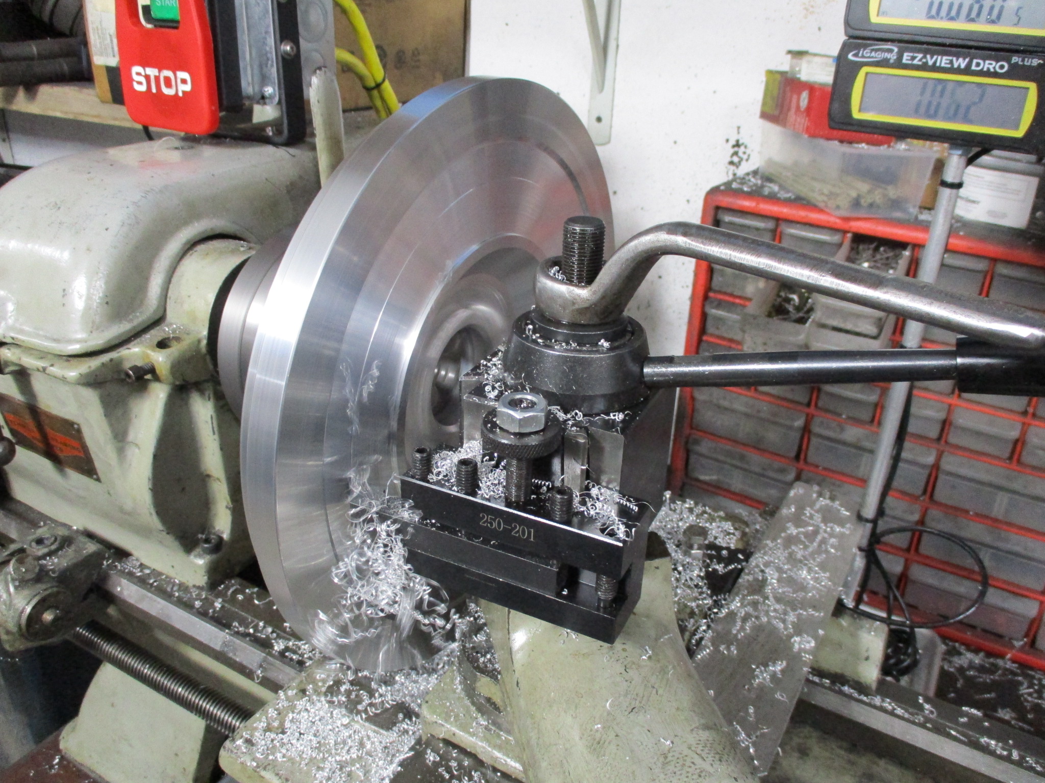
While the engine was off the work bench, I picked up a 12" Clausing Lathe sold off my Southbend 9" one. The Clausing was treated with DROs, new chuck and BXA tool holder setup. It also had the ways clearanced so that I can chuck up a LS flywheel (168 tooth ring gear knocked off).
Old Southbend:
12" Clausing:
LS flywheel chucked up:
Then I started making a new aluminum flywheel for a twin disc clutch rated for 800 hp. It is a super tight fit, but with a couple of minor modifications to the pressure plate, I was able to get full spline engagement on both discs as well as adequate finger clearance for wear.
The following 2 users liked this post by fieroguru:
Michael Yount (11-26-2022), Project GatTagO (11-26-2022)
The following 3 users liked this post by Project GatTagO:
 11-26-2022 | 03:17 PM
#453
Thread Starter
Joined: Feb 2010
Posts: 835
Likes: 221
From: Champaign, IL
It is actually 2 custom flywheels. One on post 16 on page 1 that I made for phase 1 of this build. Then this current one for the Turbo upgrade phase... but who is counting.
The following users liked this post:
Project GatTagO (11-26-2022)
11-28-2022 | 10:14 AM
#455
Joined: Aug 2007
Posts: 2,409
Likes: 107
From: Where the Navy tells me to go
Very cool. Had to go back to post #16 to see the previous setup (which also answered the one question I had - what are you using for the wear surface of the flywheel?).
12-01-2022 | 06:17 AM
#456
Thread Starter
Joined: Feb 2010
Posts: 835
Likes: 221
From: Champaign, IL
For both flywheels I used Fidanza friction plates. The N/A one was 10 1/4" version and the turbo twin disk uses a 10" one.
12-05-2022 | 12:07 PM
#457
So cool!! It's builds like this that have had me wanting to pick up a lathe and/or mill. I scored a Smithy 1340 for $750 bucks a few months back and can't wait to start doing cool stuff like this!
The following users liked this post:
Project GatTagO (12-06-2022)
12-05-2022 | 05:52 PM
#458
Thread Starter
Joined: Feb 2010
Posts: 835
Likes: 221
From: Champaign, IL
I am looking forward to seeing what you do with the Nomad!
The following users liked this post:
Project GatTagO (12-06-2022)
12-18-2022 | 04:52 PM
#459
Thread Starter
Joined: Feb 2010
Posts: 835
Likes: 221
From: Champaign, IL
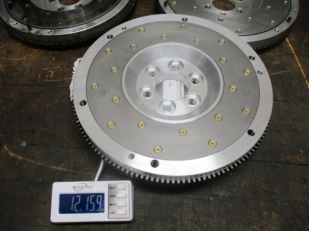
Flywheel and twin disc clutch are now done.
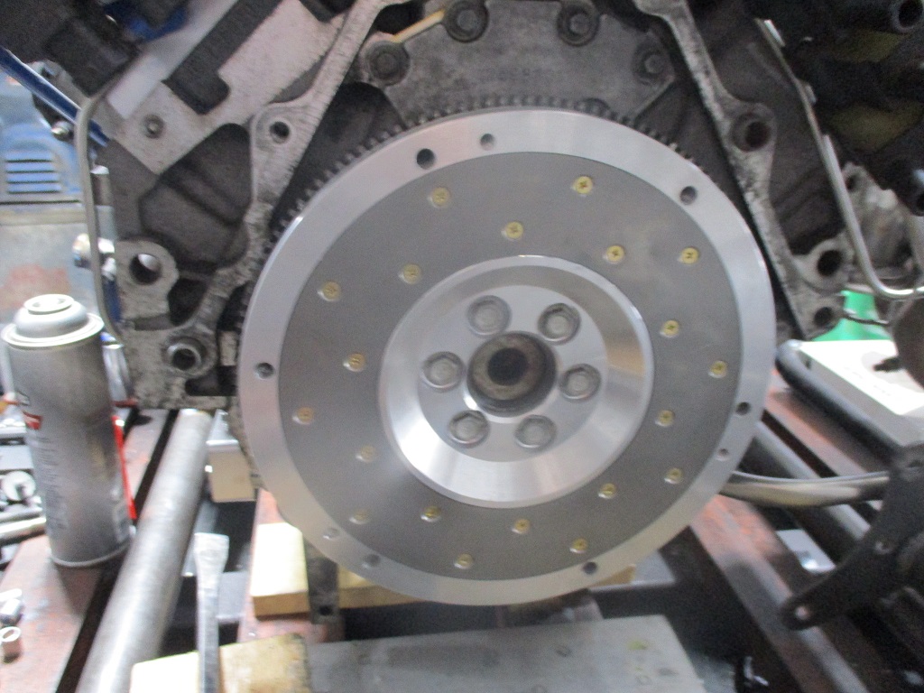
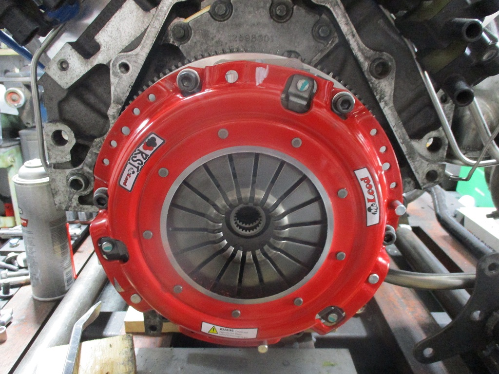
For comparison:
Stock 2.8 fiero setup is about 15 lbs for the flywheel and 15.6 lbs for the clutch/pressure plate = 30.65 lbs.
Stock 2000 LS1 is 24 lbs for the flywheel and 32 lbs for the clutch/pressure plate = 56 lbs.
LS4/F40 flywheel/twin disc clutch combo is 13 lbs for the flywheel, and 21 lbs for the clutch discs, floater plate, pressure plate and all bolts. = 34 lbs
The following 2 users liked this post by fieroguru:
AAIIIC (12-19-2022), Project GatTagO (12-18-2022)