


Coil harness junction techniques
Thread Starter
Joined: Apr 2010
Posts: 2,816
Likes: 86
From: Instagram @chevyhotrodder
Does anyone have any photos of how they did their wire junctions for coils on a custom harness?
For the power, ground, and signal ground circuits, four coils connect to a single junction before continuing on. Each junction has one in, four out for a total of five wires that need to joined. On the factory harness, this is done with mechanical wrapping of the strands which is overlaid with an adhesive heat shrink.
I am mostly interested in how the strands themselves can be joined. I have an idea on how I'd like to do it, but would be interested to see how others have accomplished this on custom harnesses. Thanks for any input!
Thread Starter
Joined: Apr 2010
Posts: 2,816
Likes: 86
From: Instagram @chevyhotrodder
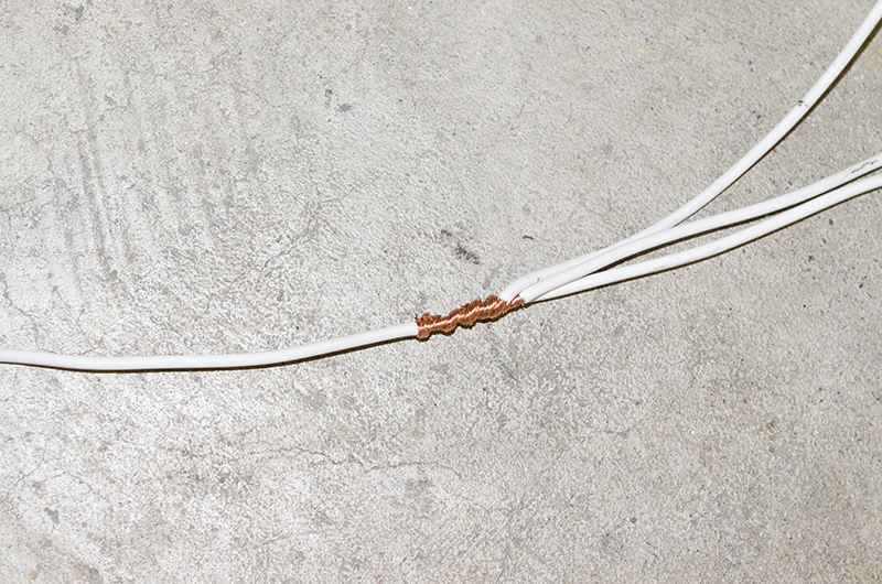
Here is a factory style junction, but I don't know what the wire strands look like inside of this.
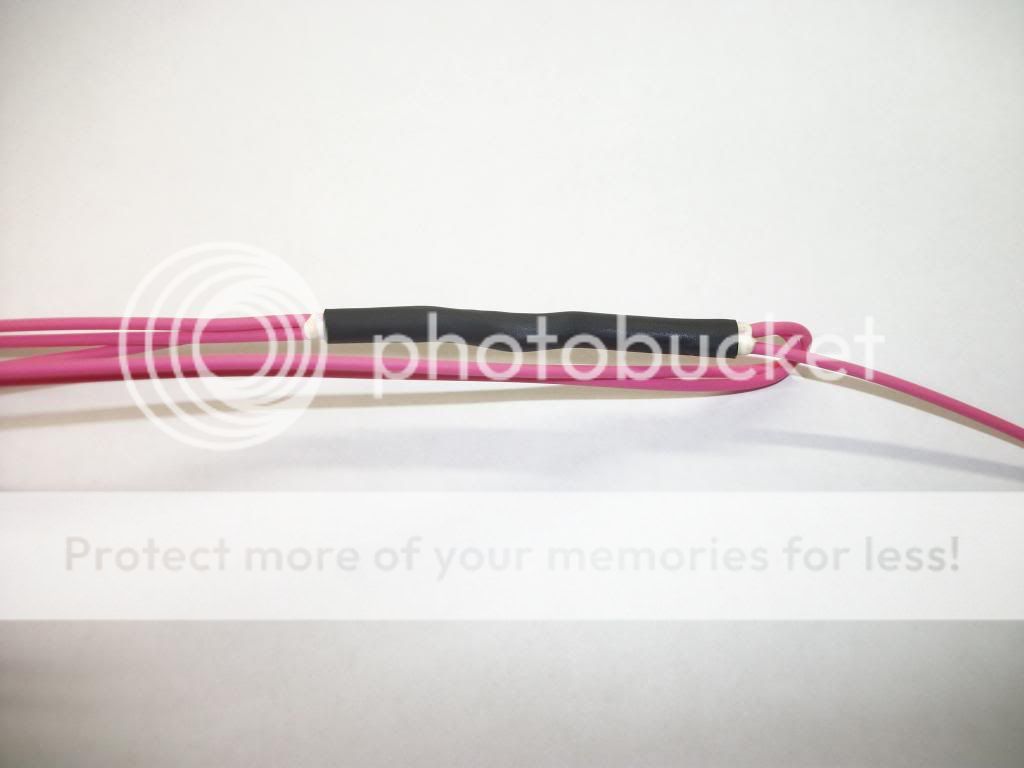
Here is the factory shrink tube with expanding foam adhesive inside: Delphi PN 12186167. They are 2.5" long according to the data sheet.http://www.mouser.com/Search/m_Produ...EaDdmQhlpZiPA=
Here are a couple ideas from BOXCHEV from this thread: https://ls1tech.com/forums/conversio...tructions.html

Here is the factory shrink tube with expanding foam adhesive inside: Delphi PN 12186167. They are 2.5" long according to the data sheet.http://www.mouser.com/Search/m_Produ...EaDdmQhlpZiPA=
Here are a couple ideas from BOXCHEV from this thread: https://ls1tech.com/forums/conversio...tructions.html
I took apart one of the larger Red wired junction.. (12 or 10 ga ?).. it was just layed together and had a metal band that clamped it all together and then they use the usual shrink tube with expanding foam adhesive.
I couldn't find any smaller pink wired one.. I'll keep looking. But I think cleaned the Junk out of the spare wire box a while ago.
BC
I couldn't find any smaller pink wired one.. I'll keep looking. But I think cleaned the Junk out of the spare wire box a while ago.
BC
From the factory its kind of a sonic weld I think. I carefully took apart a splice from part of the ground wire harness. Like said above the thick foam like glue kind of held it altogether. The wire strands all came apart once I was amble to get the heat shrink apart to look at it.
Haven't come across a source yet for that heat shrink GM uses, would like to get ahold of some.
I haven't noticed any wire splices with the metal clip on it on a LS harness, on my 88 monte however every multi wire plice has one of those crimp on wire sleeves with a little solder over it all, then they just used tape to cover it. I believe this is an old method.
When I get to a computer I will post up some pics how I did mine.
The tool junkie in me would love to have one of those ultrasonic machines, but I think my wallet would disagree..
I cut apart one of the multi-point grounds in a harness to see what the factory did some time ago and it couldn't have been anything impressive because I can't remember what it looked like.
I cut apart one of the multi-point grounds in a harness to see what the factory did some time ago and it couldn't have been anything impressive because I can't remember what it looked like.
Thread Starter
Joined: Apr 2010
Posts: 2,816
Likes: 86
From: Instagram @chevyhotrodder
Here is the factory shrink tube with expanding foam adhesive inside: Delphi PN 12186167. They are 2.5" long according to the data sheet.http://www.mouser.com/Search/m_Produ...EaDdmQhlpZiPA=
Trending Topics
Wow skipped right pass that part, didn't see the link thanks. How stiff is it after you shrink it? The stuff on the factory harness is pretty hard, not much flex to it.
How I did mine, there is one main wire. Jacket stripped in the middle.
Then strip one wire and wrap it around tight as possible.
Then keep adding wire for however many ends you need.
After that I solder the connection and double up on some heavy wall adhesive heat shrink. I make sure the solder penetrates all the way through.
LS1 Tech Stories
The Best V8 Stories One Small Block at Time

Topdon ONE vs. Artidiag 800 BT2: Which is the Diagnostic Tablet For You?
Pouria Savadkouei
Gas Monkey Built a 6-Wheel Ferrari Testarossa With a Corvette LT4 Engine
Verdad Gallardo
7 Most Reliable High-Performance Engines GM Has Ever Built
Verdad Gallardo
Amazing '71 Camaro Restomod Is Modern Muscle Car Under the Skin
Verdad Gallardo
6 Common C5 Corvette Failures and What's Involved In Repairing Them
Pouria Savadkouei
Retro Modern Bandit Pontiac Trans AM Comes With Burt Reynolds' Autograph
Verdad Gallardo
Top 10 Greatest Cadillac V Series Performance Models Ever, Ranked
Pouria Savadkouei
Top 10 Most Powerful Chevy Trucks Ever Made!

Hennessey's New Supercharged Silverado ZR2 Has 700 HP
Verdad Gallardo Thread Starter
Joined: Apr 2010
Posts: 2,816
Likes: 86
From: Instagram @chevyhotrodder
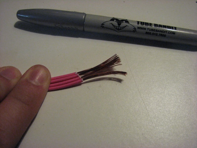
I played around last night and did my first junction. First, the following photos show a practice run on scrap wire. The first step is stripping the ends of four wires about 1". I do not twist the strands at all at this point.
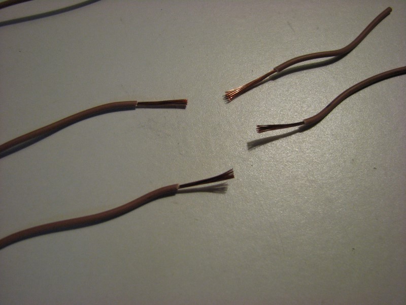
Next I joined pairs of wires by twising them around eachother. I start by putting a slight bend in both wires about half way, hook them with eachother, then carefully wrap the strands.
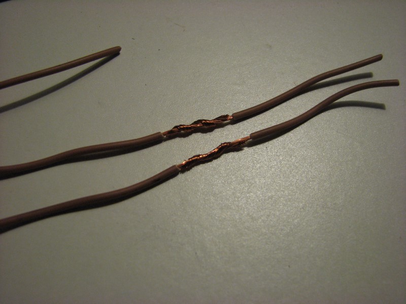
After that, I put the four wires into an X and then twist them around eachother in the same direction.

Last comes the "input" wire. I strip a lot of insulation off this one, about 2", to give plenty of strand length for wrapping.

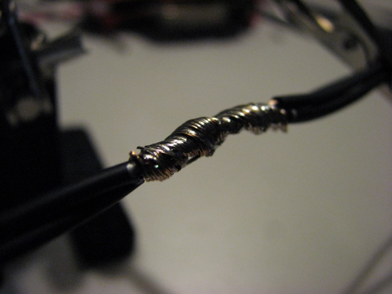
It then gets wrapped around the others, again working in the same direction. The finished wrap is shown below. I can tug on each of the individual wires and they don't budge. This joint is ready for solder.

As posted above, I worked hard to find the original Delphi adhesive shrink wrap that is used on the factory harness. It is Delphi PN 12186167. They are 2.5" long. I bought a bunch from Mouser. http://www.mouser.com/Search/m_Produ...EaDdmQhlpZiPA= Here is a photo.

Now to make my first actual junction. I followed the same sequence as above. This is for the signal ground for the odd cylinders.


The solder joint wasn't awesome, but the solder did wick around all the strands after it was heated. It really took some time to heat up with the little iron I was using. This is a big joint. A butane soldering torch would be a better solution.
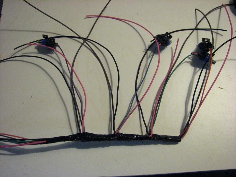
And here is the start of my coil harness for the first four (odd bank) coils.


This is going to be a lot of work!
Next I joined pairs of wires by twising them around eachother. I start by putting a slight bend in both wires about half way, hook them with eachother, then carefully wrap the strands.
After that, I put the four wires into an X and then twist them around eachother in the same direction.
Last comes the "input" wire. I strip a lot of insulation off this one, about 2", to give plenty of strand length for wrapping.
It then gets wrapped around the others, again working in the same direction. The finished wrap is shown below. I can tug on each of the individual wires and they don't budge. This joint is ready for solder.
As posted above, I worked hard to find the original Delphi adhesive shrink wrap that is used on the factory harness. It is Delphi PN 12186167. They are 2.5" long. I bought a bunch from Mouser. http://www.mouser.com/Search/m_Produ...EaDdmQhlpZiPA= Here is a photo.
Now to make my first actual junction. I followed the same sequence as above. This is for the signal ground for the odd cylinders.
The solder joint wasn't awesome, but the solder did wick around all the strands after it was heated. It really took some time to heat up with the little iron I was using. This is a big joint. A butane soldering torch would be a better solution.
And here is the start of my coil harness for the first four (odd bank) coils.
This is going to be a lot of work!

I wonder in you used one of those 8ton crimpers on ebay or the one at harborfreight with the shitty dies and make a special die for it. Twist the wires up like you do before soldering it and place it into the die and crimp it down and the die would crush the strands and form it into a solid piece of copper.
 just tossing an idea out lol.
A lot of the guys on car audio forums have been using the ebay 8 and 12ton crimpers on 1/0 gauge lugs with good results.
One cut in half

A lot of the guys on car audio forums have been using the ebay 8 and 12ton crimpers on 1/0 gauge lugs with good results.
One cut in half
Thread Starter
Joined: Apr 2010
Posts: 2,816
Likes: 86
From: Instagram @chevyhotrodder
Continuing work on my coil harness... I picked up a Portasol 125w butane soldering iron and wow, that was a great idea! The 50w Weller I've used for electronics soldering has always worked great, but it's just not powerful enough for this type of joint.


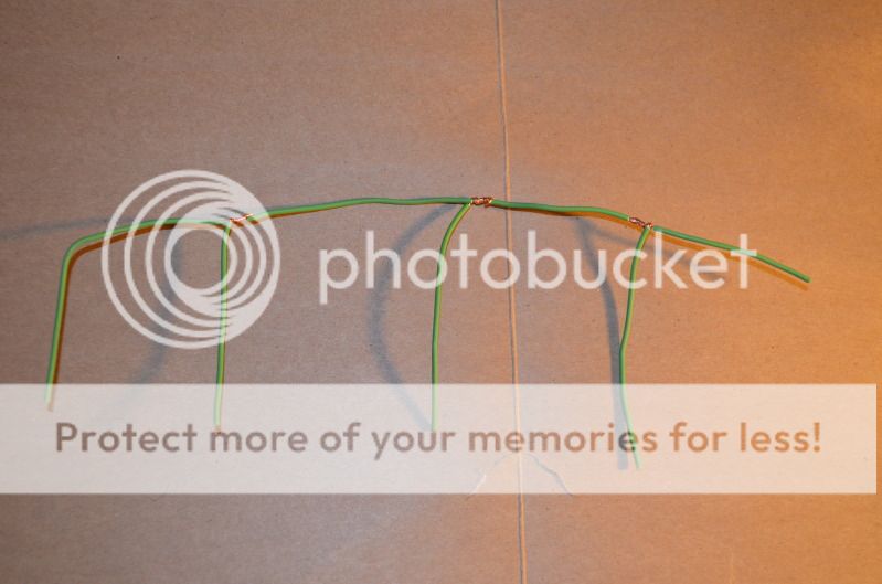
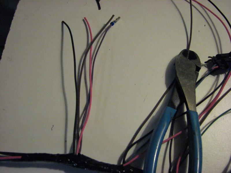
The odd bank coils and junctions went together nicely. Once I had all three junctions done, I laid them on top of the trigger wires which I had already setup to the desire length and tee-off location.

Then I wrapped the main run to get things bundled. I was surprised to find the wrapped section wasn't very big despite the junctions.
I left excess on each of the junction wires and cut them to length afterwards.
Then I added terminals, loom and heat shrink for the individual coil lengths, put the terminals in the connectors, and shrunk the ends. I used no harness wrap on these short runs and picked the smallest diameter loom I could, which doesn't have much overlap.
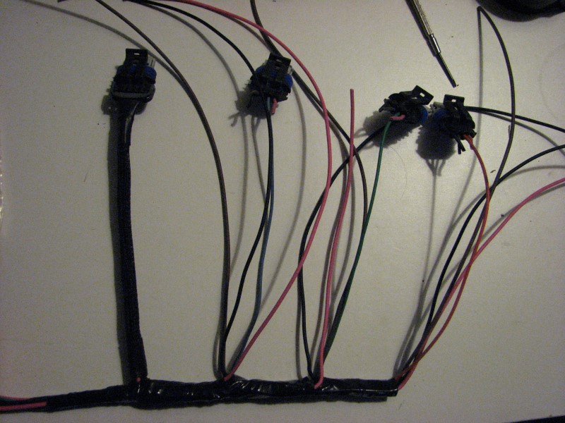
I was also in an in-between heat shrink size, so the resulting 2:1 shrink ended up open-mouth with some curl on the ends. I'm thinking about redoing the shrink on these with either a smaller size (hard to get on) or 3:1.

The odd bank coils and junctions went together nicely. Once I had all three junctions done, I laid them on top of the trigger wires which I had already setup to the desire length and tee-off location.
Then I wrapped the main run to get things bundled. I was surprised to find the wrapped section wasn't very big despite the junctions.
I left excess on each of the junction wires and cut them to length afterwards.
Then I added terminals, loom and heat shrink for the individual coil lengths, put the terminals in the connectors, and shrunk the ends. I used no harness wrap on these short runs and picked the smallest diameter loom I could, which doesn't have much overlap.
I was also in an in-between heat shrink size, so the resulting 2:1 shrink ended up open-mouth with some curl on the ends. I'm thinking about redoing the shrink on these with either a smaller size (hard to get on) or 3:1.
Thread Starter
Joined: Apr 2010
Posts: 2,816
Likes: 86
From: Instagram @chevyhotrodder
I finished up the 3 junctions for the even bank coils last night. It took about an hour now that I have the hang of it.
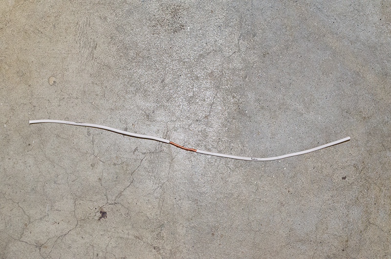
First, the signal ground junction. For both the signal ground and the main ground I used the original wire from the old harness leading up to the junction, then new 18g from there to each coil. The main ground is 16g while the signal ground is 20g. Except for the +12v line, I reused all the input lines so I could keep the factory wire colors and ECM terminals. This helped maintain colors so I didn't have to buy a bunch of striped wire. The even bank has the same colors as the odd bank, but with white stripes. Here are the wire strands wrapped, soldered and sealed.


Here is the ground junction.


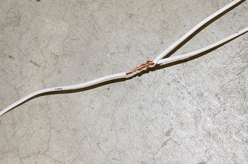
Here is the method used for the 4 coil wires coming off each junction. I started by marking the wires to get a consistent strip length.

Once stripped, I put about a 45 degree bend midway along the strands. This positions them for twisting.


Once they are twisted up, if there are strands overlapping the insulation as above, I pull the wires apart. With enough tension, they slide along one another. Next up, solder and shrink. I love this butane soldering iron!

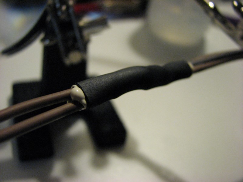
I was really excited to have a heat tip with deflector for the butane soldering iron which is meant for doing shrink tube, but in practice I am trying to complete one joint and move to the next, so the solder tip is still way too hot to remove in time to replace with the heat shrink tip. So instead I used a butane lighter to shrink the tube. As mentioned above this is the Delphi adhesive tube that's used on the factory harness. It takes a while after it's already shrunk before the adhesive starts to ooze out.

And there they are, done done done!

First, the signal ground junction. For both the signal ground and the main ground I used the original wire from the old harness leading up to the junction, then new 18g from there to each coil. The main ground is 16g while the signal ground is 20g. Except for the +12v line, I reused all the input lines so I could keep the factory wire colors and ECM terminals. This helped maintain colors so I didn't have to buy a bunch of striped wire. The even bank has the same colors as the odd bank, but with white stripes. Here are the wire strands wrapped, soldered and sealed.
Here is the ground junction.
Here is the method used for the 4 coil wires coming off each junction. I started by marking the wires to get a consistent strip length.
Once stripped, I put about a 45 degree bend midway along the strands. This positions them for twisting.
Once they are twisted up, if there are strands overlapping the insulation as above, I pull the wires apart. With enough tension, they slide along one another. Next up, solder and shrink. I love this butane soldering iron!
I was really excited to have a heat tip with deflector for the butane soldering iron which is meant for doing shrink tube, but in practice I am trying to complete one joint and move to the next, so the solder tip is still way too hot to remove in time to replace with the heat shrink tip. So instead I used a butane lighter to shrink the tube. As mentioned above this is the Delphi adhesive tube that's used on the factory harness. It takes a while after it's already shrunk before the adhesive starts to ooze out.
And there they are, done done done!
Bandit
Are you redoing the complete ground harness? I think my original ground harness got tossed when I removed it from the complete engine harness. So I have to make one from scratch. I was wondering where and how many ground points you are using?
I know one goes on the back of the heads, my motor mounts put the head too close to the firewall so I moved one ground point to the front of the heads instead.
Thread Starter
Joined: Apr 2010
Posts: 2,816
Likes: 86
From: Instagram @chevyhotrodder
BOXCHEV sorry for the very late reply, but just came across this while reviewing old threads. On my harness, the ignition coils go to a single ground which is attached to the back of the driver's cylinder head. The main ground for the ECM and the MAF ground go to the front of the passenger cylinder head. Given where I located my ECM, I probably should have ran the ECM ground to the back of the driver's cylinder head because the distance is much shorter, but running it to the front of the passenger head maintained the end to end stock ground wire which uses different terminals from the rest of the harness.