
72 Nova - The Booboo Project LS/4L65e


 07-22-2015, 06:20 PM
#182
Sebtarta I can't tell you how jealous I am of your now-running extremely clean swap. I keep watching the video thinking about how sanitary everything turned out. Thanks for the inspiration.
 08-04-2015, 08:31 AM
#184
Well, I am at the DMV right now. Brought my sleeping pillow at the same time.
Managed to fix the trans problem. Pin E was not getting a 12v feed from the ECM. So it was time to track the problem. Pin E at the trans harness shares the pink O2 wire and MAF, so I did a resistance check between PIN E and the pink O2 wire. Got nothing, but while.moving around under the car I saw a jump on resistance. I thought I was seeing things, so measured again, nothing move harness and got a reading. So it basically told me the wire had a splice somewhere. Fixed the issue, got my 12v at Pin E and suddenly look the trans works fine. No codes and all gears work fine.
It definitely needs a tune, as it shifts all over the place, so I hope to be able to flat bed the car down to the tuner on friday and be able to drive back that same day.
Driving the car around the block, the sound you get from the exhaust is just what I wanted, good job Todd. Deep sound at low RPMs and strangled cat sound when at WOT. Will post another video when car is running good and alignment done and such.
08-04-2015, 01:54 PM
#185
Well, I am at the DMV right now. Brought my sleeping pillow at the same time.
Managed to fix the trans problem. Pin E was not getting a 12v feed from the ECM. So it was time to track the problem. Pin E at the trans harness shares the pink O2 wire and MAF, so I did a resistance check between PIN E and the pink O2 wire. Got nothing, but while.moving around under the car I saw a jump on resistance. I thought I was seeing things, so measured again, nothing move harness and got a reading. So it basically told me the wire had a splice somewhere. Fixed the issue, got my 12v at Pin E and suddenly look the trans works fine. No codes and all gears work fine.
It definitely needs a tune, as it shifts all over the place, so I hope to be able to flat bed the car down to the tuner on friday and be able to drive back that same day.
Driving the car around the block, the sound you get from the exhaust is just what I wanted, good job Todd. Deep sound at low RPMs and strangled cat sound when at WOT. Will post another video when car is running good and alignment done and such.
Managed to fix the trans problem. Pin E was not getting a 12v feed from the ECM. So it was time to track the problem. Pin E at the trans harness shares the pink O2 wire and MAF, so I did a resistance check between PIN E and the pink O2 wire. Got nothing, but while.moving around under the car I saw a jump on resistance. I thought I was seeing things, so measured again, nothing move harness and got a reading. So it basically told me the wire had a splice somewhere. Fixed the issue, got my 12v at Pin E and suddenly look the trans works fine. No codes and all gears work fine.
It definitely needs a tune, as it shifts all over the place, so I hope to be able to flat bed the car down to the tuner on friday and be able to drive back that same day.
Driving the car around the block, the sound you get from the exhaust is just what I wanted, good job Todd. Deep sound at low RPMs and strangled cat sound when at WOT. Will post another video when car is running good and alignment done and such.
 09-13-2015, 03:33 PM
#186
For the condenser I got that idea from reading your post about how you had to make the aluminum brackets to make it fit. Thus how I fitted mine using the same concept.
The EZ fittings is the best thing ever invented. Part of the fittings I bought from this guy on ebay
http://stores.ebay.com/askacss2012/
I also bought some stuff from www.buspartsexperts.com. I recommend for people thinking about buying g a Vintage Air system to just buy the evaporator unit, then source the rest as it will end up being cheaper and probably better parts as well.
I managed to finish mounting the evaporator unit, running the lines and all. I found that using a Sanden SD7 with the ports on the side and using the 90* fittings with service ports it hits the inner fender well.

So I bought the splices with service ports from www.buspartsexperts.com and finished the lines. Not the prettiest of all but it was the only option I had.

The EZ fittings is the best thing ever invented. Part of the fittings I bought from this guy on ebay
http://stores.ebay.com/askacss2012/
I also bought some stuff from www.buspartsexperts.com. I recommend for people thinking about buying g a Vintage Air system to just buy the evaporator unit, then source the rest as it will end up being cheaper and probably better parts as well.
I managed to finish mounting the evaporator unit, running the lines and all. I found that using a Sanden SD7 with the ports on the side and using the 90* fittings with service ports it hits the inner fender well.
So I bought the splices with service ports from www.buspartsexperts.com and finished the lines. Not the prettiest of all but it was the only option I had.
I purchased the universal EZ clip kit from Summit for something like $350, then had to add a few other fittings as well. I wish I had searched eBay first. My high pressure side fitting hit the inner fender well also, and I did the same 90 and T-splice you did, however my low pressure side fit fine because it was a 508 rather than an SD7.
Keep up the good work!
12-11-2015, 04:15 AM
#189
Teching In

Join Date: Sep 2015
Posts: 4
Likes: 0
Received 0 Likes
on
0 Posts
Just read your build as well! Very nice thread. I saw your video several months ago on youtube while looking for swap videos and I just now found the thread, this is so nice to read the effort and detail provided.
I sent a buddy a link to your video a couple weeks ago - the installation is so clean we thought it was the LS3 connect and cruise kit with full GMPP accessory drive kit and full harness, etc. Just thought you'd appreciate that (meant as a compliment) this looks 100% OEM and that is what I am going to strive for.
Well done.
02-09-2016, 02:09 PM
#190
Just read your build as well! Very nice thread. I saw your video several months ago on youtube while looking for swap videos and I just now found the thread, this is so nice to read the effort and detail provided.
I sent a buddy a link to your video a couple weeks ago - the installation is so clean we thought it was the LS3 connect and cruise kit with full GMPP accessory drive kit and full harness, etc. Just thought you'd appreciate that (meant as a compliment) this looks 100% OEM and that is what I am going to strive for.
Well done.
I sent a buddy a link to your video a couple weeks ago - the installation is so clean we thought it was the LS3 connect and cruise kit with full GMPP accessory drive kit and full harness, etc. Just thought you'd appreciate that (meant as a compliment) this looks 100% OEM and that is what I am going to strive for.
Well done.
In October I went with a friend of mine who has a '80 Malibu to a car show in NY, some of the roads were back hilly roads, we did some spirited driving and that was a testament to how fun you can make a car be.
I had the ACDelco ceramic pads, and they were too soft. Not enough bite when you start pushing the car. So i swapped to some Carbotech 1521 and it made a huge difference.
Now I moved to FL and unfortunately the valve train noise got louder, and i wanted to change the cam due to the fact that when I had the car tuned it was difficult to have it idle, O2 sensors and fuel trimming had to be turned off.....and yeah for the amount of gas i was going through it was easier getting the 383
 02-09-2016, 02:09 PM
#191
So this is what happens when you know deep down that the sound of the engine is not right.

Talking with some engine builders, tuners and such, it seemed that the cam i had installed in the engine was meant more for LS2 heads rather than LS3. Ls3 call for a larger degree separation, and the cam I have is only 8�, which is great for LS1 or LS2 heads. This is because of the intake flow the LS3 heads have that call for a higher degree separation.
Either way, i was going to replace the lifters and such so I took the heads off on the passanger side, and found the answer to all my concerns.


So yeah, now i need to take the engine out and see what my next step is. it is very hard to do this in a HOA place, specially after I moved I do not have that much garage space either. OH well, there is a solution for everything.
Cleaned the pistons, this is the driver side, and you can faintly see the intake valve had contact with the piston.

Manged to remove the balancer and front timing cover. It shows the marks being at 6, 12 and 3 with TDC on #1.

I then decided to measure the timing chain to see what was installed, and to my finding the Katech C5r chain and the one installed are same thicknesses. Measured several times and got the same readings.


It was time to remove the cam, but for that I had to remove the AC condenser as i had the 4th part of the cam still in the block. Sliding it sideways, then turning and all I managed to remove it.

Here are the 1st few lobes, 2400 miles on said new cam...

The main 1st cam bearing does not look too good. The scratches are not that deep but you can feel them with your nail.

Any suggestions would be great, thanks.
Talking with some engine builders, tuners and such, it seemed that the cam i had installed in the engine was meant more for LS2 heads rather than LS3. Ls3 call for a larger degree separation, and the cam I have is only 8�, which is great for LS1 or LS2 heads. This is because of the intake flow the LS3 heads have that call for a higher degree separation.
Either way, i was going to replace the lifters and such so I took the heads off on the passanger side, and found the answer to all my concerns.
So yeah, now i need to take the engine out and see what my next step is. it is very hard to do this in a HOA place, specially after I moved I do not have that much garage space either. OH well, there is a solution for everything.
Cleaned the pistons, this is the driver side, and you can faintly see the intake valve had contact with the piston.
Manged to remove the balancer and front timing cover. It shows the marks being at 6, 12 and 3 with TDC on #1.
I then decided to measure the timing chain to see what was installed, and to my finding the Katech C5r chain and the one installed are same thicknesses. Measured several times and got the same readings.
It was time to remove the cam, but for that I had to remove the AC condenser as i had the 4th part of the cam still in the block. Sliding it sideways, then turning and all I managed to remove it.
Here are the 1st few lobes, 2400 miles on said new cam...
The main 1st cam bearing does not look too good. The scratches are not that deep but you can feel them with your nail.
Any suggestions would be great, thanks.
02-09-2016, 03:43 PM
#192

The valve reliefs on those pistons make absolutely no sense. I understand it's so the pistons can be use on either sides, but that's a canted valve design. Both eyebrows should be on the top half of the piston. Either way, looks like the cam was starved or oil. What kind of oil pressure did you have? We're the cam bearings line honed after assembly (gm line hones the cam journals with the bearings in to make them all true)? If the cam and lifters were starved for oil casing the lifters to hang up, that could be why the valves hit the pistons.
02-10-2016, 08:43 AM
#193
From my research those are the stock LS3 pistons, but I am not sure as I do not find many posts showing stock LS3 pistons.
As for the oil pressure I had 30psi +/- on idle and 40psi when driving. Sometimes 45-50psi at WOT.
Then more reading on this forum shows that cam bearing sometimes show scratches as min, and the thing is that the st lobe on the cam is smooth with no pitting or scratches wither. So not sure if that bearing is ok or it has to be replaced.
02-10-2016, 11:22 AM
#194

So why does the cam look so bad?
 03-02-2016, 07:59 PM
#196
The main thing about taking the heads off was to replace the crappy china casting heads that came with the engine to 823 casting L92 heads. I had them checked and cleaned and the heads are in perfect condition. At the same time replace the valve train....so here we go


I also have brand new Rockers with the BTR trunion upgrade. So maybe I could just install all of this making sure it is done right, and if something goes wrong on the top end I know I can only blame myself.
During the weekend I went ahead and started putting the heads together. I cleaned them, sanded, prepped them and masked them up for a quick Dupli-color DE1615 Ceramic Aluminum Engine Paint. It came out really good, will post a better pic of the heads, valve covers, timing cover painted later on.

Got all the parts ready, plus my second LSX mini spring compressor as the one I bought a long time ago is somewhere in a box from the move and I cannot find it. It is very easy to use, just have to make sure you place the spring in a certain way. When you start compressing the spring it has the tendency to start 'leaning' toward the rocker arm stud. So when starting place the spring with the retainer sitting just covering 1/4 of the valve stem on the stud side.


One thing installing the Viton BTR valve seals. You need a 12mm 12pt long socket. Lubricate the seal with oil, make sure to place a locator 1st, then slide through the valve stem and start tapping on the socket with a hammer. You will hear a slight tone change when the seal is flushed all the way down. There will also be about 1/8" gap between the valve seal and the spring locator. The black seals are for intake and the brown for exhaust.
Back to the engine saga. My engine never came with the chain dampener. Being a Gen IV block the holes were already there. Why they did not put one is a mystery. The only way of installing this timing chain dampener part #12588670 is by removing the oil pump.
So after dropping the oil pan one more time, i decided to leave the long bolts on the back just a few threads in, all the rest of the 10mm bolts were removed, and the oil pan was sitting on the cross member. Unfortunately you are not able to slide the pan out due to the rear hitting the bellhousing and the middle sitting on top of the front sway bar. Unless you take the sway bar off, which that was not going to happen, then you can remove oil pan 100%.
I managed to get the first bolt on the oil pickup tube with a cut allen key. The second one, which sits in the inside, was not as easy at all. The only way I managed to get the allen bolt out was by fabricating a very special and sophisticated tool. I small piece of gorilla duct tape to hold the allen bit with a 12pt 5/16 wrench. You can also see 2 brand new hex 8mm hex bolts that will replace the bolts that came with the Holley 302-2 pan. I doubt I will ever have to dig into this again, but you never know.

Guess what, it worked!

Oil pump was out, which allowed me to install the chain dampener, and from there I moved to installing the cam and the Katech C5r chain as well.

On the cam retaining plate (which I used a new one just in case) I added some oil around the seal in the back plus where the cam sits on it. I also added more oil on the front where the timing gear sits as well. Torque the 4 T40 flat head bolts to 11 ft/lbs.
I also have brand new Rockers with the BTR trunion upgrade. So maybe I could just install all of this making sure it is done right, and if something goes wrong on the top end I know I can only blame myself.
During the weekend I went ahead and started putting the heads together. I cleaned them, sanded, prepped them and masked them up for a quick Dupli-color DE1615 Ceramic Aluminum Engine Paint. It came out really good, will post a better pic of the heads, valve covers, timing cover painted later on.
Got all the parts ready, plus my second LSX mini spring compressor as the one I bought a long time ago is somewhere in a box from the move and I cannot find it. It is very easy to use, just have to make sure you place the spring in a certain way. When you start compressing the spring it has the tendency to start 'leaning' toward the rocker arm stud. So when starting place the spring with the retainer sitting just covering 1/4 of the valve stem on the stud side.
One thing installing the Viton BTR valve seals. You need a 12mm 12pt long socket. Lubricate the seal with oil, make sure to place a locator 1st, then slide through the valve stem and start tapping on the socket with a hammer. You will hear a slight tone change when the seal is flushed all the way down. There will also be about 1/8" gap between the valve seal and the spring locator. The black seals are for intake and the brown for exhaust.
Back to the engine saga. My engine never came with the chain dampener. Being a Gen IV block the holes were already there. Why they did not put one is a mystery. The only way of installing this timing chain dampener part #12588670 is by removing the oil pump.
So after dropping the oil pan one more time, i decided to leave the long bolts on the back just a few threads in, all the rest of the 10mm bolts were removed, and the oil pan was sitting on the cross member. Unfortunately you are not able to slide the pan out due to the rear hitting the bellhousing and the middle sitting on top of the front sway bar. Unless you take the sway bar off, which that was not going to happen, then you can remove oil pan 100%.
I managed to get the first bolt on the oil pickup tube with a cut allen key. The second one, which sits in the inside, was not as easy at all. The only way I managed to get the allen bolt out was by fabricating a very special and sophisticated tool. I small piece of gorilla duct tape to hold the allen bit with a 12pt 5/16 wrench. You can also see 2 brand new hex 8mm hex bolts that will replace the bolts that came with the Holley 302-2 pan. I doubt I will ever have to dig into this again, but you never know.
Guess what, it worked!
Oil pump was out, which allowed me to install the chain dampener, and from there I moved to installing the cam and the Katech C5r chain as well.
On the cam retaining plate (which I used a new one just in case) I added some oil around the seal in the back plus where the cam sits on it. I also added more oil on the front where the timing gear sits as well. Torque the 4 T40 flat head bolts to 11 ft/lbs.
03-02-2016, 08:00 PM
#197
Piston to valve clearance. Yup, it takes a lot of time to do. I transformed a lifter to solid lifter by removing the spring and adding three washers and a nut, i believe they are all size M6.

Later i placed both lifters on cylinder #1, added the old head gaskets and placed some modeling clay covering the top half of the piston. Used a 1/4" thick piece across the piston and covered the #1 valves with some oil to prevent them from sticking to the clay. Mounted the heads and torqued to 30 ft/lbs. Then added the 7.4" pushrods, rockers and bolted those to 22 ft/lbs.

Same time I found some color on the titanium retainers, no idea how i cut the tip of my left pinky, but some Krazy glue fixed the cut and kept going.

After rotating the engine slowly on consistent twice, it was time to remove the heads and find out how much clearance there is between the valve and the piston.


On the above picture you have the cutout for the intake on the left and exhaust on the right. Remember that the piston have an exhaust relief and not on the intake. The minimum spec for clearance is 0.080" for intake and 0.100" on exhaust. I ended up with 0.126" clearance for the intake. I called BTR to double check on what info they have on their LS3 Stage II cam, and they said they usually have 0.040" more than minimum, 0.080 + 0.040= 0.120", clay method is not 100% accurate but give a small margin of error I was off by 0.006" which is fine.

At the same time I took a picture of the exhaust lobe at full lift. The coils are not touching, picture is deceiving, but were close.

My CDI Torque 3/8 torque wrench decided to break one of the paws. I called Snap-On and told me to contact this other company to buy the parts for the ratchet section. Parts were a total of $8 plus $10 service charge and $10 for shipping.

I need this guy working ASAP as I need to finish torquing bolts at 37 ft/lbs or less. The 1/2 torque wrench is big and cumbersome at the same time when in need in small areas.
I used this spray paint to repaint the heads, covers and timing cover. Worked great and looks really good. Dupli-Color DE1650


When time came to torque the heads down to the block I opted out for the good old GM bolts part # 17800568. I still do not understand why people buy the ARP bolts or studs. The bolts are used on the high end GM engines as well holding plenty of power. I understand the concept of being able to reuse them, but I can buy 7 sets of these for the price of the ARP stud set. Besides I do not plan in swapping heads either every month.

It could be be that people use the ARP for the easy way out in having to torque the heads down. The GM bolts require angle torquing.

Bought the Jegs Angle Torque Gauge #81692
The torque process for the GM 17800568 bolts is as follows.

For the rockers, set the crank and cam shaft gear to 12 o'clock and make sure to lubricate the rockers as much as you can. Then follow the directions bellow

After doing the above procedure, I rotate the engine a few times and follow the steps again. Wanted to make sure the rockers seated correctly and the bolts were torqued down to spec.
It was time to place the timing cover back on and the harmonic balancer. remove the old seal from the timing cover and press in the new one. Should be fairly easy to do. Once done, place the cover and hold it together with the 10 bolts. Slide the balancer on the crankshaft and get the installer ready. I bought a M16x2 rod (if anyone wants a section PM) some nuts and washers. Then went to Lowes MotorSports and bought a 2" pipe and cap. Drilled a whole on the cap and used that to push the harmonic in.

With the old harmonic bolt, finish pressing the balancer by torquing it down to 240 ft/lbs, then remove it and torque down the new GM harmonic bolt #12557840 with some red loctite to 37 ft/lbs and then angle torque to 140�
I also bought a flywheel locking tool on ebay here if you want to buy the locking tool and balancer installer you get them here

Once the balancer is fully installed, remove the flywheel locking tool, rotate the crank a few time to let the timing cover seal settle in place. then torque all bolts to 22 ft/lbs, remember the 2 bolts for the oil pan that bolt to the cover.
Installed the intake and water pump. The intake bolts are torque on 1st pass to 44 in/lbs and the 2nd pass to 89 in/lbs using the sequence below. for the water pump I added new gaskets some blue loctite and torqued all 6 water pump bolts to 22 ft/lbs
i have a little bit more to go, but waiting on a few things in order to be able to prime the engine with oil and then finish bolting the rest. Plus I need my 3/8 torque wrench working as well, which it should arrive at the end of this week.
Most of the info was taken from How To Build and Modify GM LS-Series Engine book by Joseph Potak as well as these two threads, My DIY LS7 Headswap and DIY: LS3 Camshaft Install (a lot of pictures, may take a moment to load). ALso searching online for other specs and information on how other people did what. This process was fun after all. I feel like buying a brand new block and build a new 408 long block and have it sit in the garage as art.
Later i placed both lifters on cylinder #1, added the old head gaskets and placed some modeling clay covering the top half of the piston. Used a 1/4" thick piece across the piston and covered the #1 valves with some oil to prevent them from sticking to the clay. Mounted the heads and torqued to 30 ft/lbs. Then added the 7.4" pushrods, rockers and bolted those to 22 ft/lbs.
Same time I found some color on the titanium retainers, no idea how i cut the tip of my left pinky, but some Krazy glue fixed the cut and kept going.
After rotating the engine slowly on consistent twice, it was time to remove the heads and find out how much clearance there is between the valve and the piston.
On the above picture you have the cutout for the intake on the left and exhaust on the right. Remember that the piston have an exhaust relief and not on the intake. The minimum spec for clearance is 0.080" for intake and 0.100" on exhaust. I ended up with 0.126" clearance for the intake. I called BTR to double check on what info they have on their LS3 Stage II cam, and they said they usually have 0.040" more than minimum, 0.080 + 0.040= 0.120", clay method is not 100% accurate but give a small margin of error I was off by 0.006" which is fine.
At the same time I took a picture of the exhaust lobe at full lift. The coils are not touching, picture is deceiving, but were close.
My CDI Torque 3/8 torque wrench decided to break one of the paws. I called Snap-On and told me to contact this other company to buy the parts for the ratchet section. Parts were a total of $8 plus $10 service charge and $10 for shipping.
I need this guy working ASAP as I need to finish torquing bolts at 37 ft/lbs or less. The 1/2 torque wrench is big and cumbersome at the same time when in need in small areas.
I used this spray paint to repaint the heads, covers and timing cover. Worked great and looks really good. Dupli-Color DE1650
When time came to torque the heads down to the block I opted out for the good old GM bolts part # 17800568. I still do not understand why people buy the ARP bolts or studs. The bolts are used on the high end GM engines as well holding plenty of power. I understand the concept of being able to reuse them, but I can buy 7 sets of these for the price of the ARP stud set. Besides I do not plan in swapping heads either every month.
It could be be that people use the ARP for the easy way out in having to torque the heads down. The GM bolts require angle torquing.
Bought the Jegs Angle Torque Gauge #81692
The torque process for the GM 17800568 bolts is as follows.
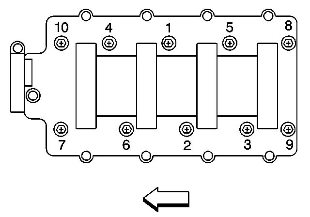
- Torque M11 bolts to 22 ft/lbs in the sequence from 1-10 in the diagram below
- Loosen 1 full turn all the M11 bolts using the 10-1 sequence
- Torque them back to 22 ft/lbs in the 1-10 order
- Mark each bolt as best as you can with a straight line pointing up, as this will help you gauge your angle as you tighten
- Torque to 90� M11 bolts in order of 1-10 using the angle torque wrench (you might need a second person to hold it for you)
- Torque to 70� M11 bolts in the order of 1-10
- Almost there, finish by torquing all M8 bolts to 22 ft/lbs on 11-15 order
- Repeat the same process for the other side
For the rockers, set the crank and cam shaft gear to 12 o'clock and make sure to lubricate the rockers as much as you can. Then follow the directions bellow
After doing the above procedure, I rotate the engine a few times and follow the steps again. Wanted to make sure the rockers seated correctly and the bolts were torqued down to spec.
It was time to place the timing cover back on and the harmonic balancer. remove the old seal from the timing cover and press in the new one. Should be fairly easy to do. Once done, place the cover and hold it together with the 10 bolts. Slide the balancer on the crankshaft and get the installer ready. I bought a M16x2 rod (if anyone wants a section PM) some nuts and washers. Then went to Lowes MotorSports and bought a 2" pipe and cap. Drilled a whole on the cap and used that to push the harmonic in.
With the old harmonic bolt, finish pressing the balancer by torquing it down to 240 ft/lbs, then remove it and torque down the new GM harmonic bolt #12557840 with some red loctite to 37 ft/lbs and then angle torque to 140�
I also bought a flywheel locking tool on ebay here if you want to buy the locking tool and balancer installer you get them here
Once the balancer is fully installed, remove the flywheel locking tool, rotate the crank a few time to let the timing cover seal settle in place. then torque all bolts to 22 ft/lbs, remember the 2 bolts for the oil pan that bolt to the cover.
Installed the intake and water pump. The intake bolts are torque on 1st pass to 44 in/lbs and the 2nd pass to 89 in/lbs using the sequence below. for the water pump I added new gaskets some blue loctite and torqued all 6 water pump bolts to 22 ft/lbs
i have a little bit more to go, but waiting on a few things in order to be able to prime the engine with oil and then finish bolting the rest. Plus I need my 3/8 torque wrench working as well, which it should arrive at the end of this week.
Most of the info was taken from How To Build and Modify GM LS-Series Engine book by Joseph Potak as well as these two threads, My DIY LS7 Headswap and DIY: LS3 Camshaft Install (a lot of pictures, may take a moment to load). ALso searching online for other specs and information on how other people did what. This process was fun after all. I feel like buying a brand new block and build a new 408 long block and have it sit in the garage as art.
03-02-2016, 08:04 PM
#198
So I oil primed the engine. Parts that I used
-8 AN Male Flare To 16mm x 1.5 Threads Straight Adapter
-8 An Straight Hose End Push Lock Tite Fitting Jic Black
Then went to Lowes, bought a drill pump, 1/2 clear hose and the hose ends.

Also used the Dorman 300-126 Power Steering Pulley which is the same pulley that Holley sells in order to have the clearance to the driver side UCA. You can see how much smaller it is from the CTS-v pulley, but at least I can seat it flush and not having to stop 0.150" short.

Before installing the AC back, I had to fill it up with oil. When I removed it back then when taken the engine apart, I managed to leak oil from the compressor. I called Vintage Air and they suggested to let it drain, then fill up 3.4oz of PAG 100 oil. Went to Sanden's website and found the recommended type of oil for the compressor. Manged to find the oil here.

Got the compressor done, mounted everything and bought a new belt as my PSP pulley size changed. Ended up with a 6PK60985

Should be starting the engine tomorrow I hope. Added all the fluid and made sure there were no leaks.
Here is a video of the car starting. I had to prime the engine either way with the fuel pump off and no plugs. Once I got the pressure, which took 4 cranks of probably 5 seconds each time to get the pressure.
Car runs 100% better than before. Idle is perfect, the valve train noise I used to have before is gone. Just need to retune it and find something else to do on the car.
-8 AN Male Flare To 16mm x 1.5 Threads Straight Adapter
-8 An Straight Hose End Push Lock Tite Fitting Jic Black
Then went to Lowes, bought a drill pump, 1/2 clear hose and the hose ends.
Also used the Dorman 300-126 Power Steering Pulley which is the same pulley that Holley sells in order to have the clearance to the driver side UCA. You can see how much smaller it is from the CTS-v pulley, but at least I can seat it flush and not having to stop 0.150" short.
Before installing the AC back, I had to fill it up with oil. When I removed it back then when taken the engine apart, I managed to leak oil from the compressor. I called Vintage Air and they suggested to let it drain, then fill up 3.4oz of PAG 100 oil. Went to Sanden's website and found the recommended type of oil for the compressor. Manged to find the oil here.
Got the compressor done, mounted everything and bought a new belt as my PSP pulley size changed. Ended up with a 6PK60985
Should be starting the engine tomorrow I hope. Added all the fluid and made sure there were no leaks.
Here is a video of the car starting. I had to prime the engine either way with the fuel pump off and no plugs. Once I got the pressure, which took 4 cranks of probably 5 seconds each time to get the pressure.
Car runs 100% better than before. Idle is perfect, the valve train noise I used to have before is gone. Just need to retune it and find something else to do on the car.
03-02-2016, 08:25 PM
#199
So I oil primed the engine. Parts that I used
-8 AN Male Flare To 16mm x 1.5 Threads Straight Adapter
-8 An Straight Hose End Push Lock Tite Fitting Jic Black
Then went to Lowes, bought a drill pump, 1/2 clear hose and the hose ends.
1972 Chevy Nova Booboo - LSx oil primer tool - YouTube
Also used the Dorman 300-126 Power Steering Pulley which is the same pulley that Holley sells in order to have the clearance to the driver side UCA. You can see how much smaller it is from the CTS-v pulley, but at least I can seat it flush and not having to stop 0.150" short.
Before installing the AC back, I had to fill it up with oil. When I removed it back then when taken the engine apart, I managed to leak oil from the compressor. I called Vintage Air and they suggested to let it drain, then fill up 3.4oz of PAG 100 oil. Went to Sanden's website and found the recommended type of oil for the compressor. Manged to find the oil here.
Got the compressor done, mounted everything and bought a new belt as my PSP pulley size changed. Ended up with a 6PK60985
Should be starting the engine tomorrow I hope. Added all the fluid and made sure there were no leaks.
Here is a video of the car starting. I had to prime the engine either way with the fuel pump off and no plugs. Once I got the pressure, which took 4 cranks of probably 5 seconds each time to get the pressure.
1972 Chevy Nova Booboo - Startup after heads and valve train swap - YouTube
1972 Chevy Nova Booboo - Rolling out after valve train swap - YouTube
Car runs 100% better than before. Idle is perfect, the valve train noise I used to have before is gone. Just need to retune it and find something else to do on the car.