


My 69 Camaro LS1 Swap
Thread Starter
Teching In
Joined: Sep 2005
Posts: 45
Likes: 0
From: Grand Haven, Michigan
Nice looking car, only question is there a reason you didn't run the fuel line up the driver side to eliminate having to route the fuel line over the intake manifold, would have made a cleaner look in the engine bay? I am not sure but I think you can still flip the fuel rail 180* so that the connection would line up to your passenger side fuel line routing. Just food for thought?
Yes I agree there is a lot going on the driver side by the brake booster, I am pretty sure the fuel rail can be flipped 180* putting the fuel inlet on the passenger side, which would also tidy things up.
Thread Starter
Teching In
Joined: Sep 2005
Posts: 45
Likes: 0
From: Grand Haven, Michigan
Didn't even think about rotating the fuel rail. Good to know if I ever dig back into it.
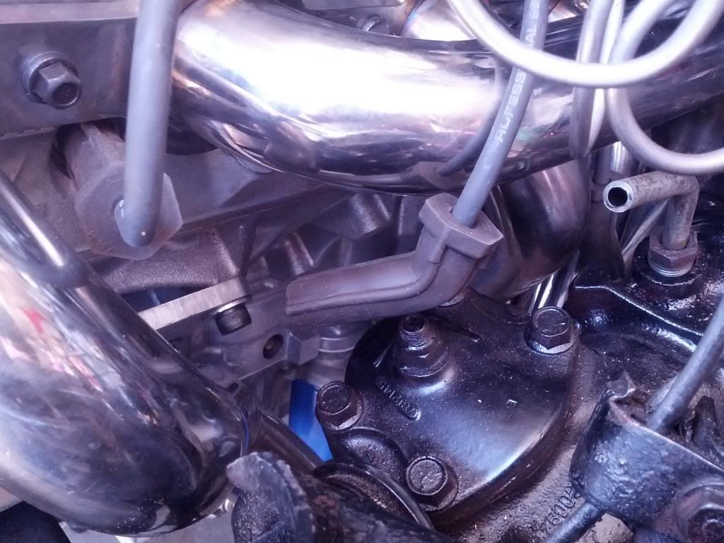
Here are a few pics of how I connected up my fuel system in the engine bay. For the connection to the fuel rail I used a Swagelok 3/8" 90 degree compression fitting (SS-600-9) which connected to the fuel rail. Then I used a tube insert with a -6AN connection (SS-6-TA-1-6AN) on the end of that. At the frame rail I used a straight tube coupler (SS-600-6) to connect to the 3/8" line and another one of the AN adapters in that. I then coupled it all with a parker stainless braided teflon hose with AN fittings on each end. I think the parker hose is there 919 series.
Here are a few pics of how I connected up my fuel system in the engine bay. For the connection to the fuel rail I used a Swagelok 3/8" 90 degree compression fitting (SS-600-9) which connected to the fuel rail. Then I used a tube insert with a -6AN connection (SS-6-TA-1-6AN) on the end of that. At the frame rail I used a straight tube coupler (SS-600-6) to connect to the 3/8" line and another one of the AN adapters in that. I then coupled it all with a parker stainless braided teflon hose with AN fittings on each end. I think the parker hose is there 919 series.
10 Second Club


Joined: Aug 2010
Posts: 4,464
Likes: 192
From: Harford Co. Maryland
That spot was/is my biggest issue also....at the brake booster.
I'm carbed and used the 1" set-back mounts with the DynaTech 1 7/8" headers...the plug wire hits, so I had to "adjust" it some
I'm carbed and used the 1" set-back mounts with the DynaTech 1 7/8" headers...the plug wire hits, so I had to "adjust" it some
Thread Starter
Teching In
Joined: Sep 2005
Posts: 45
Likes: 0
From: Grand Haven, Michigan
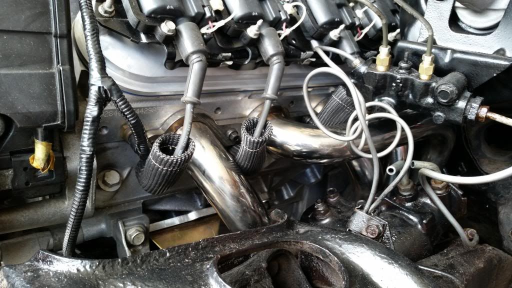
Here are a few shots of how I made the spark plug wires fit on the driver side. The Texas Speed headers are just like the Dynatech ones and you have to bend the boot to get it to clear. I was able to cut the original end off the wire and then crimp on a new longer end with extra parts I had laying around from an old wire set. The new ends were slightly longer and I was able to bend them at a good angle to clear everything and slide the original boot back on. I then put on heat sleeves for extra protection.


Thread Starter
Teching In
Joined: Sep 2005
Posts: 45
Likes: 0
From: Grand Haven, Michigan
Thanks! I have lots of pics, so I will post what I can.
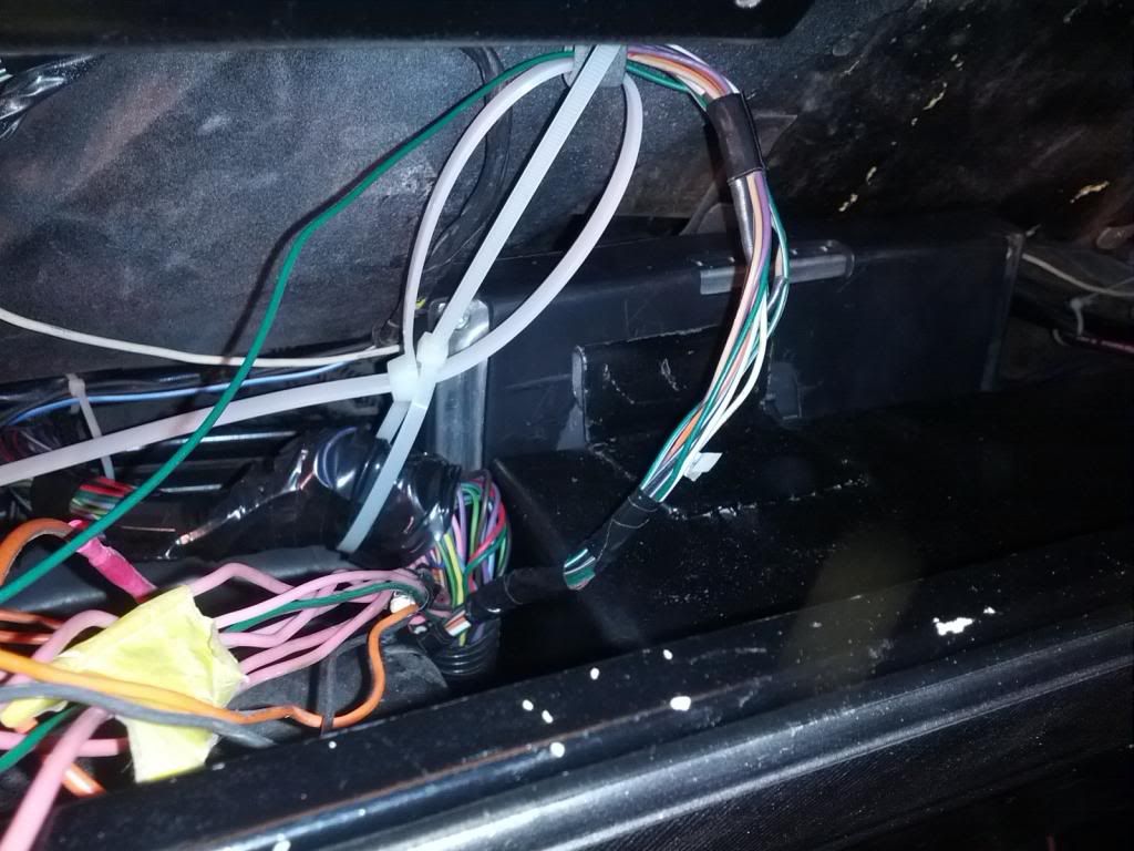
I did all of the wiring modifications to the car and engine harness myself and am glad I did. Learned a lot on how this engine is set up. I ended up using a Cooper Bussman fuse block and power relay module that has been posted on this forum a few times. To mount this, I made a new glovebox and mounted it inside. Along with that I made the glovebox shallower and mounted the computer behind it. Using the original computer mount I can now easily remove the computer when needed.
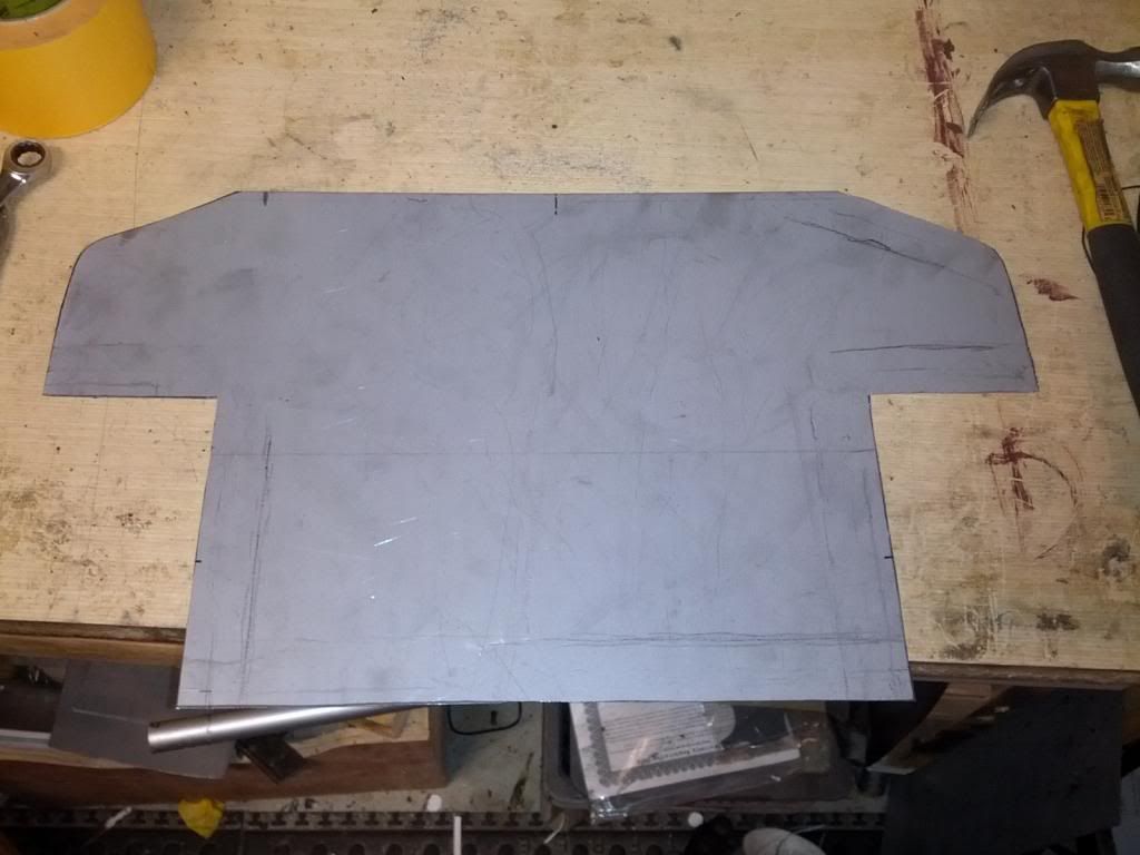
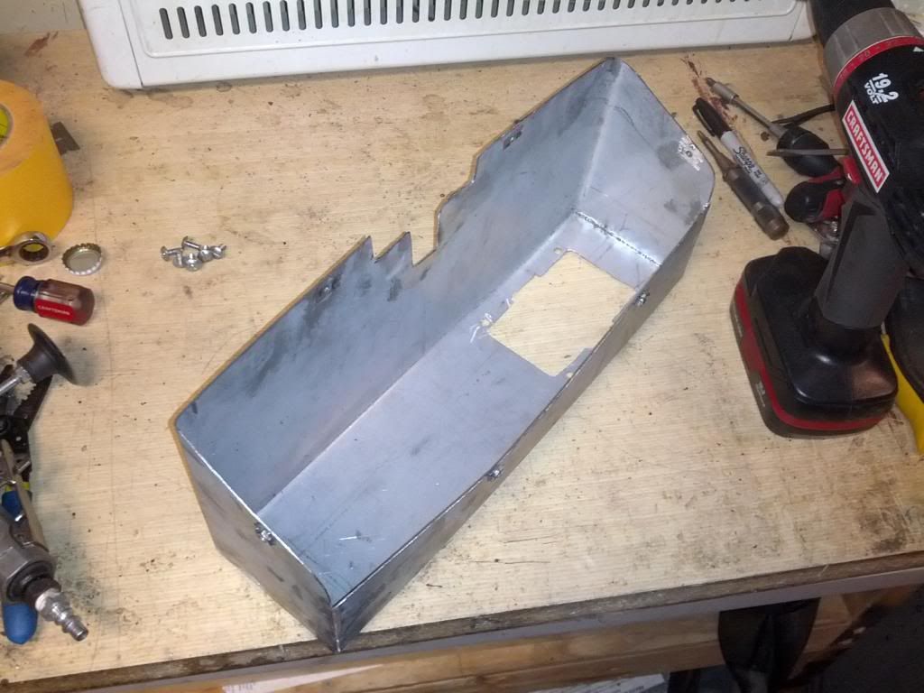
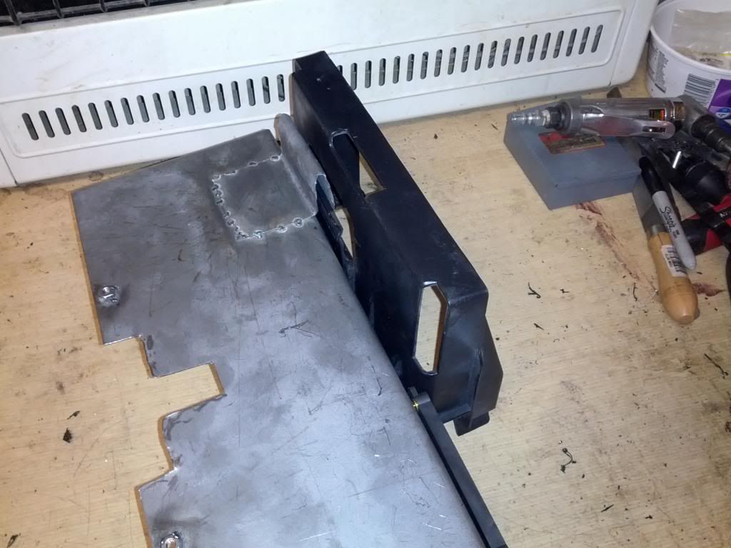
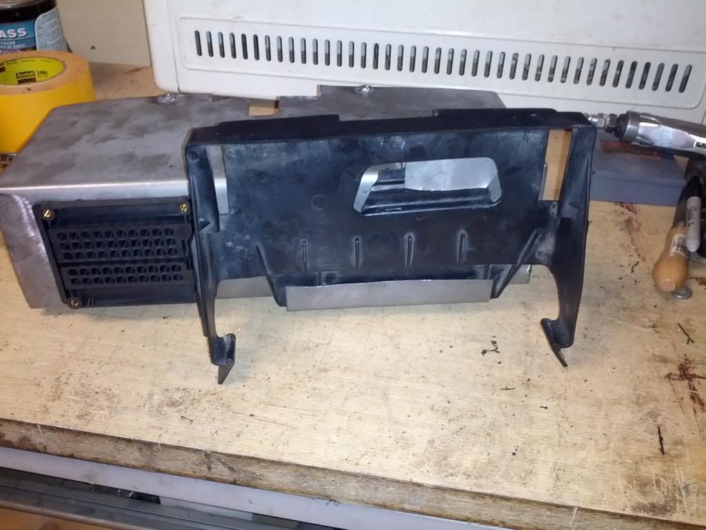
I did all of the wiring modifications to the car and engine harness myself and am glad I did. Learned a lot on how this engine is set up. I ended up using a Cooper Bussman fuse block and power relay module that has been posted on this forum a few times. To mount this, I made a new glovebox and mounted it inside. Along with that I made the glovebox shallower and mounted the computer behind it. Using the original computer mount I can now easily remove the computer when needed.


LS1 Tech Stories
The Best V8 Stories One Small Block at Time

Retro Modern Bandit Pontiac Trans AM Comes With Burt Reynolds' Autograph
Verdad Gallardo
Top 10 Greatest Cadillac V Series Performance Models Ever, Ranked
Pouria Savadkouei
Top 10 Most Powerful Chevy Trucks Ever Made!

Hennessey's New Supercharged Silverado ZR2 Has 700 HP
Verdad Gallardo
Coachbuilt N2A Anteros Is an LS2-Powered C6 Corvette In Italian Clothes
Verdad Gallardo
Awesome K5 Blazer Restomod Comes With C7 Corvette Power
Verdad Gallardo
10 Camaros You Should Never Buy

10 LS Engine Myths That Refuse to Die
Verdad Gallardo
Five Reasons the Camaro Was the Most Pivotal Player in the Pony Car Wars 2.0
Brett Foote Thread Starter
Teching In
Joined: Sep 2005
Posts: 45
Likes: 0
From: Grand Haven, Michigan
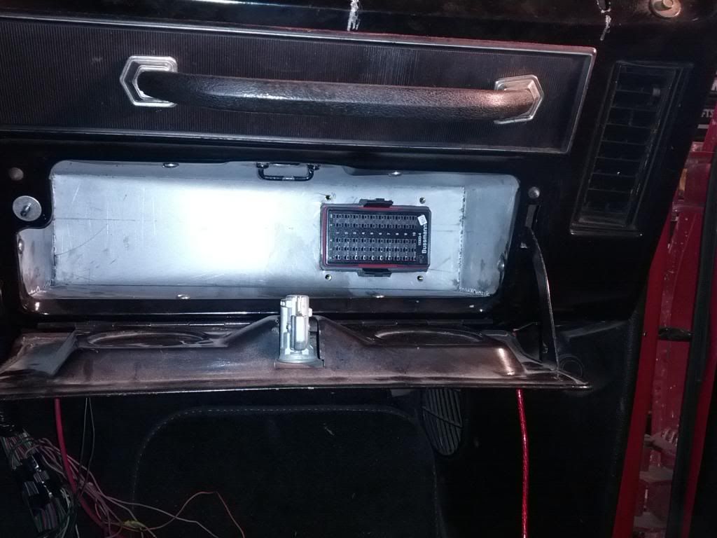
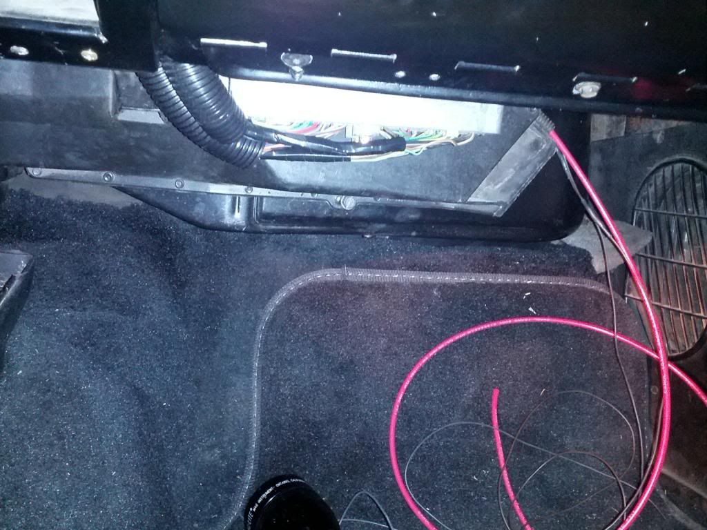
Pic of the power relay module mounted on the dash crossbar next to the ash tray and the clearance for the computer behind the glove box. Pay no attention to the mess of wires.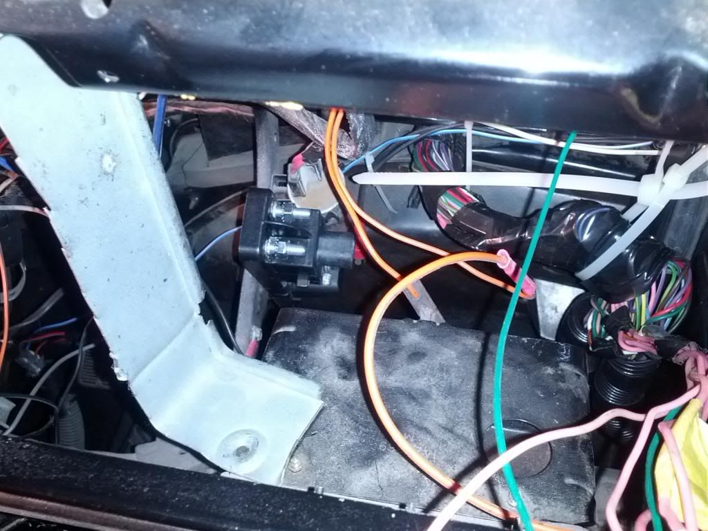


Thread Starter
Teching In
Joined: Sep 2005
Posts: 45
Likes: 0
From: Grand Haven, Michigan
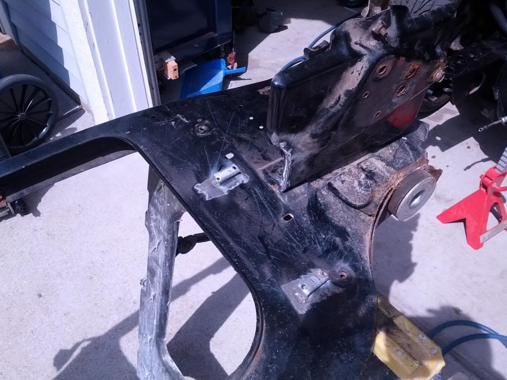
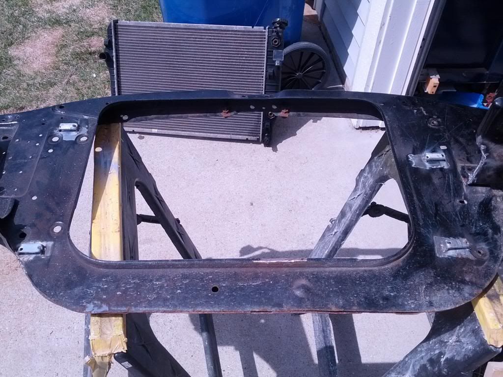
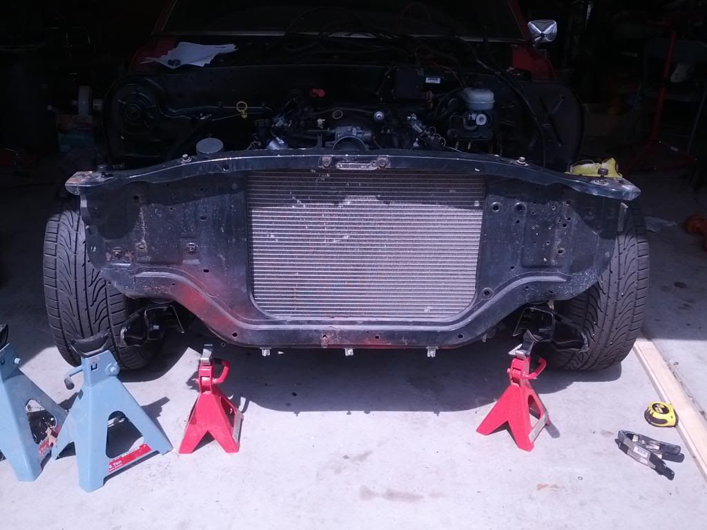
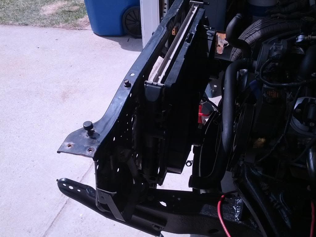
I used the stock 4th gen radiator and fans. I welded tabs on the core support to hang it and added tabs on the bottom of the core support that can be unbolted to drop the radiator. I also notched the battery tray to be able to slide the radiator over a little more.


That's a pretty piece. That sender hugs the block really nice, like it was meant for it.
Thread Starter
Teching In
Joined: Sep 2005
Posts: 45
Likes: 0
From: Grand Haven, Michigan
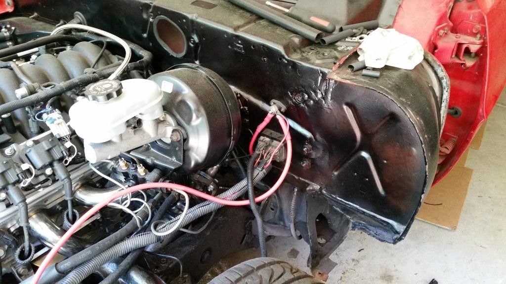
Here are a few pics of how I ran my power in the engine compartment.
4ga. cable down to the starter from the battery front post. 4ga. cable from the top post to a 200 amp fuse. Ground from the battery to the block and to the frame.
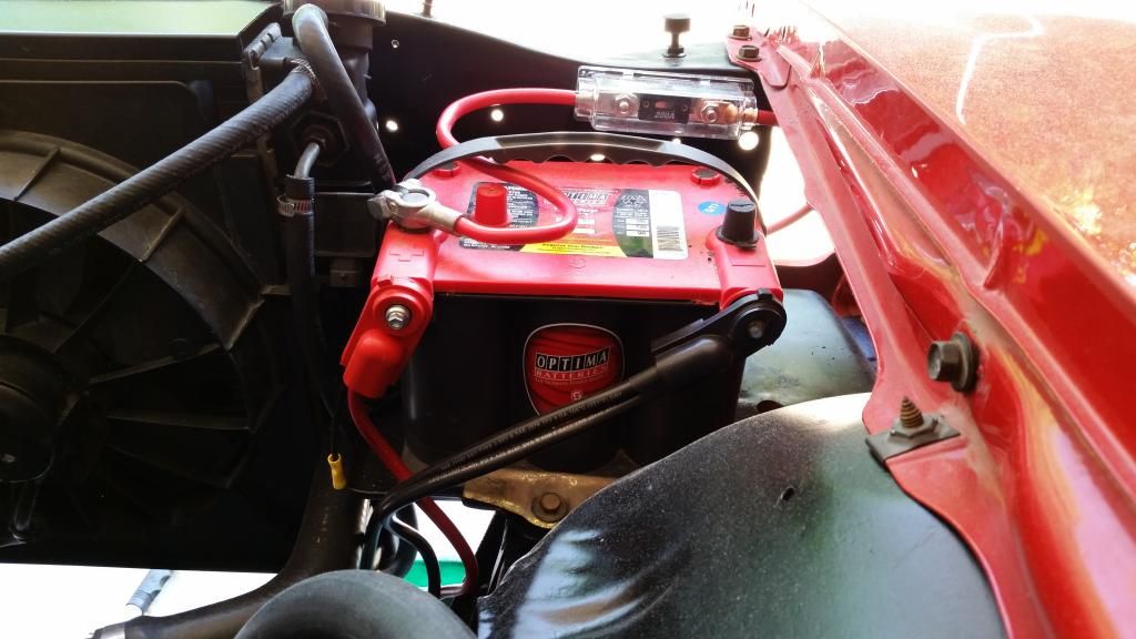
Next from the fuse above the battery I ran 4ga. across the the other side of the radiator support to a battery post. This provides power for the headlights/fans and is where the alternator connects.
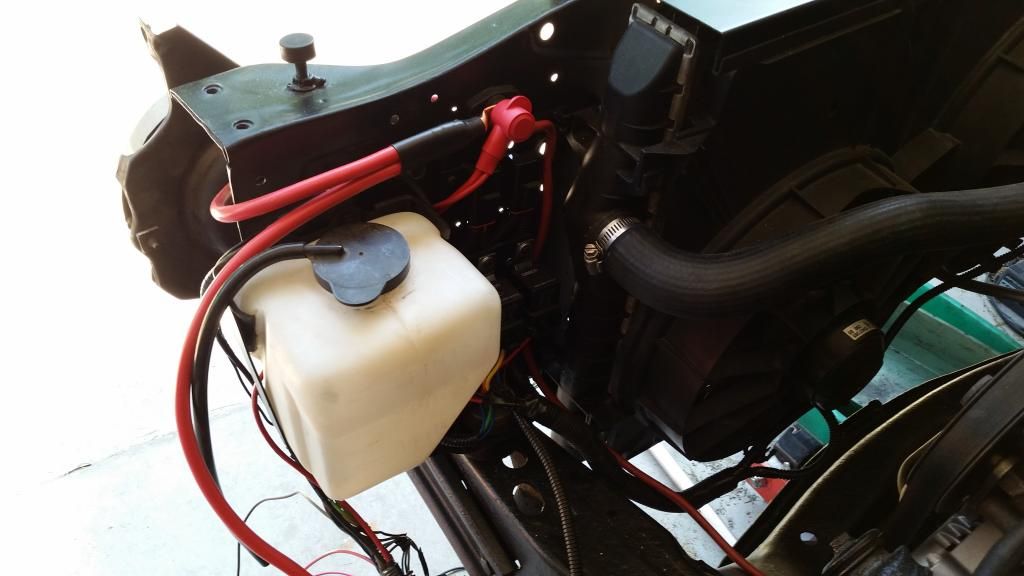
From that post I have another 4ga. wire going to another post up by the brake booster. From there power is provided to the wiper motor and all the rest of the car.


