
1967 Cougar build (over 500 pictures and videos)
 05-09-2015, 02:16 PM
#401

Cool LCD. Now you can watch **** while driving. Hey, you ARE a guy !
keep the great work coming Andrew !!
keep the great work coming Andrew !!
 05-09-2015, 07:03 PM
#402
TECH Senior Member
Thread Starter
iTrader: (7)

Today I wanted to figure out the radiator hose situation. I went to the local auto parts store and they were nice enough to let me look at all of their hoses. I found a top hose that fit perfectly.
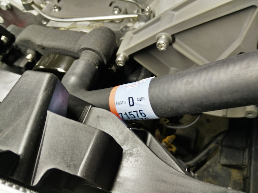

At the top of the radiator the hose expands to 1.5", which fits the inlet perfectly.
The bottom was a different story. The outlet on the radiator is 1.75" and the hose needed to make a pretty tight 90 degree bend to ever have a chance to mating up with the inlet of the water pump. I messed around with various hoses, but it wasn't going to happen with a big 1.75" hose.
So I decided to trim the radiator outlet and weld on a reducer which would allow me to use a 1.5" hose, which is the same size as the inlet on the LS water pump.

With the smaller diameter hose, I was able to combine two section of 90 degree hose to form a S shape, which connected the dots. I used the Gates heat shrink radiator hose clamp to make the hose look seamless.
I was able to sell the steel wheels that were on the car, so now I can order up some front tires, but in the meantime, the front wheels look pretty good.

Tomorrow the plan is to take the stock drum brakes off and mock up the disk brake conversion kit and see how they fit inside the wheels. I think I will need a spacer, but hopefully .5" will do the trick. I also have a set of 3" ARP studs to go on all 4 corners.
Andrew
At the top of the radiator the hose expands to 1.5", which fits the inlet perfectly.
The bottom was a different story. The outlet on the radiator is 1.75" and the hose needed to make a pretty tight 90 degree bend to ever have a chance to mating up with the inlet of the water pump. I messed around with various hoses, but it wasn't going to happen with a big 1.75" hose.
So I decided to trim the radiator outlet and weld on a reducer which would allow me to use a 1.5" hose, which is the same size as the inlet on the LS water pump.
With the smaller diameter hose, I was able to combine two section of 90 degree hose to form a S shape, which connected the dots. I used the Gates heat shrink radiator hose clamp to make the hose look seamless.
I was able to sell the steel wheels that were on the car, so now I can order up some front tires, but in the meantime, the front wheels look pretty good.
Tomorrow the plan is to take the stock drum brakes off and mock up the disk brake conversion kit and see how they fit inside the wheels. I think I will need a spacer, but hopefully .5" will do the trick. I also have a set of 3" ARP studs to go on all 4 corners.
Andrew
05-11-2015, 11:25 AM
#403
TECH Senior Member
Thread Starter
iTrader: (7)
Yesterday I decided to tackle the disk brake conversion. Getting the front drum off was pretty straight forward. Remove the dust cap, cotter pin, nut, and the drum slipped right off.

Once the drum is removed, I took off the whole drum brake assembly and was left with the bare spindle.

I am using the GT-2008FT kit from Mustang Steve:
http://www.mustangsteve.com/cobrabrakes.html
The kit is designed to use 2005-2010 Mustang GT calipers with 12.5" rotors. However, through a little searching around I found that the V6 Mustangs basically the same calipers as the GTs, but with a smaller, 11.5" rotors. The only difference in the caliper is the abutment, so this told me that the V6 brakes should fit with Steve's brackets. He and I actually exchanged some emails, and while he couldn't guarantee fitment, he didn't see any issues. This was a good enough gamble for me to take, because with 15" wheels, there was no way that I was going to make a 12.5" rotor fit.
Steve's kit includes very nice (laser?) cut brackets. The first bracket bolts to the spindle using bolts supplied in the kit.

Then another bracket is bolted in place.

At that point it was time to mock up the caliper abutment, and this is where I ran into problems.

Looks like I need about 1/8" of clearance in order for the abutment to be bolted to the bracket. I stopped working on it at that point, but the plan is to take a little off the abutment and a little off the interfering bracket.
Andrew
Once the drum is removed, I took off the whole drum brake assembly and was left with the bare spindle.
I am using the GT-2008FT kit from Mustang Steve:
http://www.mustangsteve.com/cobrabrakes.html
The kit is designed to use 2005-2010 Mustang GT calipers with 12.5" rotors. However, through a little searching around I found that the V6 Mustangs basically the same calipers as the GTs, but with a smaller, 11.5" rotors. The only difference in the caliper is the abutment, so this told me that the V6 brakes should fit with Steve's brackets. He and I actually exchanged some emails, and while he couldn't guarantee fitment, he didn't see any issues. This was a good enough gamble for me to take, because with 15" wheels, there was no way that I was going to make a 12.5" rotor fit.
Steve's kit includes very nice (laser?) cut brackets. The first bracket bolts to the spindle using bolts supplied in the kit.
Then another bracket is bolted in place.
At that point it was time to mock up the caliper abutment, and this is where I ran into problems.
Looks like I need about 1/8" of clearance in order for the abutment to be bolted to the bracket. I stopped working on it at that point, but the plan is to take a little off the abutment and a little off the interfering bracket.
Andrew
05-11-2015, 04:18 PM
#406

See you can still make the Dells..............
05-11-2015, 08:55 PM
#407
TECH Senior Member
Thread Starter
iTrader: (7)
More progress on the brakes today. I was able to drop off the hub at a local car shop and they took out the old studs and replaced them with some 3" long ARP studs.

I then marked the caliper abutment and went to work on it with my bench grinder. It only took a little time and it turned out pretty good.

The next step was to mark the caliper bracket and clearance it as well. You see where I marked it with a Sharpie.

Once that was done, the caliper bolted in place without drama.

The next order of business was to tap on the rotor centering ring that is included with Steve's kit. This is there to make sure that the rotor is hub centric. I used a drift and tapped it on until it was even with the face of the rotor.

With that done, I could finally mock up the rotor and see how it all looks together.

I mocked up the wheel, and there was not chance that it was going to clear the caliper. It wasn't so much the diameter as it was the fact that the inside of the wheel is almost flat and there is very little caliper clearance.
So I stacked a couple of old lug nuts, which came out to about 1.2" and that actually gave me more clearance than I needed.

I ordered a 1" spacer which will be enough for the wheel to clear the caliper.
Here is what it will look like when all said and done.

One little project at a time.
Andrew
I then marked the caliper abutment and went to work on it with my bench grinder. It only took a little time and it turned out pretty good.
The next step was to mark the caliper bracket and clearance it as well. You see where I marked it with a Sharpie.
Once that was done, the caliper bolted in place without drama.
The next order of business was to tap on the rotor centering ring that is included with Steve's kit. This is there to make sure that the rotor is hub centric. I used a drift and tapped it on until it was even with the face of the rotor.
With that done, I could finally mock up the rotor and see how it all looks together.
I mocked up the wheel, and there was not chance that it was going to clear the caliper. It wasn't so much the diameter as it was the fact that the inside of the wheel is almost flat and there is very little caliper clearance.
So I stacked a couple of old lug nuts, which came out to about 1.2" and that actually gave me more clearance than I needed.
I ordered a 1" spacer which will be enough for the wheel to clear the caliper.
Here is what it will look like when all said and done.
One little project at a time.
Andrew
05-11-2015, 10:20 PM
#408
TECH Addict
iTrader: (19)
Join Date: Aug 2007
Location: Where the Navy tells me to go
Posts: 2,405
Received 106 Likes
on
88 Posts

For my Subaru engine swap I had to monkey around with the cooling system, and my (very short) upper hose is two bends butted together. Right now there's a ~1.5" long piece of aluminum tubing (with the ends swaged) holding those two short bends together. I'm sure it'll work fine as is, but it would look cleaner to not have those 2 "extra" hose clamps on there.
05-12-2015, 10:43 AM
#409
TECH Senior Member
Thread Starter
iTrader: (7)
I've never heard of those heat shrink radiator hose clamps before - pretty slick. Maybe a stupid question - do you have a short hose nipple inside the 2 hoses, and then the Gates heat shrink on the outside? Or did you just butt the two hoses together and then do the heat shrink? I'm assuming there's a short piece of pipe on the inside of the hose bends so that the clamp has something to clamp against, if that makes sense.
For my Subaru engine swap I had to monkey around with the cooling system, and my (very short) upper hose is two bends butted together. Right now there's a ~1.5" long piece of aluminum tubing (with the ends swaged) holding those two short bends together. I'm sure it'll work fine as is, but it would look cleaner to not have those 2 "extra" hose clamps on there.
For my Subaru engine swap I had to monkey around with the cooling system, and my (very short) upper hose is two bends butted together. Right now there's a ~1.5" long piece of aluminum tubing (with the ends swaged) holding those two short bends together. I'm sure it'll work fine as is, but it would look cleaner to not have those 2 "extra" hose clamps on there.
I like to use these:
http://www.jagsthatrun.com/Pages/Par...eSplicers.html
Looking at your picture, I think you can probably use one Gates clamp to span both hose ends and make that look really clean.
Andrew
05-12-2015, 11:42 AM
#410
TECH Addict
iTrader: (19)
Join Date: Aug 2007
Location: Where the Navy tells me to go
Posts: 2,405
Received 106 Likes
on
88 Posts
Cool, thanks for confirming that. And those JTR pieces are nice, I'll have to bookmark that one. (I had the local machine shop weld the aluminum header in that picture together for me, and had them make me a coupler with some of the leftover material.)


 05-14-2015, 02:02 PM
#414
TECH Resident

I like those mono-ball shock top mounts. Interesting design. I also like the continuity of the finishes on the wheels, accessory drives, etc.
Great job!
Will you eventually clear coat the entire car to protect / lock in the patina?
Any prediction on 1/4 mile times? Shall we start a pool??
Doug
Great job!
Will you eventually clear coat the entire car to protect / lock in the patina?
Any prediction on 1/4 mile times? Shall we start a pool??
Doug
05-14-2015, 02:08 PM
#415
TECH Senior Member
Thread Starter
iTrader: (7)
Did you notice that the calipers match the red plug wires?
 (not that there is anything wrong with that)...
I am not doing a single bit of body work on this car. One thing that does concern me is that the door handles were shaved. This might be a problem at the drag strip...
My guess is low 12s...
Andrew
05-14-2015, 02:12 PM
#416
TECH Resident
Hey Andrew,
I totally overlooked that minutia (calipers and plug wires matching... is that like carpets matching the drapes? ), but am not surprised given the well thought out nature of what you are doing!!
I look forward to each day's updates. Makes me pine for a new project of my own.
Doug
I totally overlooked that minutia (calipers and plug wires matching... is that like carpets matching the drapes?
), but am not surprised given the well thought out nature of what you are doing!! I look forward to each day's updates. Makes me pine for a new project of my own.
Doug
05-15-2015, 10:10 AM
#417
TECH Senior Member
Thread Starter
iTrader: (7)
So...I share the good and the bad.
I stuck the clutch line into the bellhousing so it would be "safe" then of course I forgot about it and proceeded to start the engine.

Nothing like making a $90 bonehead mistake.
Andrew
I stuck the clutch line into the bellhousing so it would be "safe" then of course I forgot about it and proceeded to start the engine.
Nothing like making a $90 bonehead mistake.
Andrew
 05-16-2015, 10:26 PM
#420
TECH Senior Member
Thread Starter
iTrader: (7)
Today was one of those days where I worked a lot but I don't feel like I got much done. One very none glamorous project that was done was the heater core. I don't know if it was bad or not, but I really didn't want to have a 50 year old core going bad on me after I get everything done, so I replaced it. For the life of me I can't figure out why Ford didn't design the core so that the heater hoses would hook up in the engine bay. Instead, the hoses go through the firewall and have to be hooked up blind. Not a clever design.
The other, more useful task that I accomplished was finding a place for the Dominator ECU. The ECU is massive and there isn't much room under the dash, so I decided that it can live on the back of the glove box door. I welded some bolts directly to the door and it's pretty sturdy.

The next big task that I got mostly done is the mount for the electronic throttle pedal. The firewall isn't very flat where the pedal is supposed to go, so I had to make some brackets that would give the pedal a nice flat spot to mount.
First, I made a little bracket that bolts to the firewall just below where the old pedal used to pass through the firewall. That hole was used to route all of the ECU wiring.

I welded two 3/8" bolts to the bracket, so tightening them from the engine compartment would be a one man affair.

Next, I made another bracket that bolts to the first bracket and goes down to meet the firewall.

The carpet covers all of it nicely and now I have a solid place where I will mount the gas pedal.
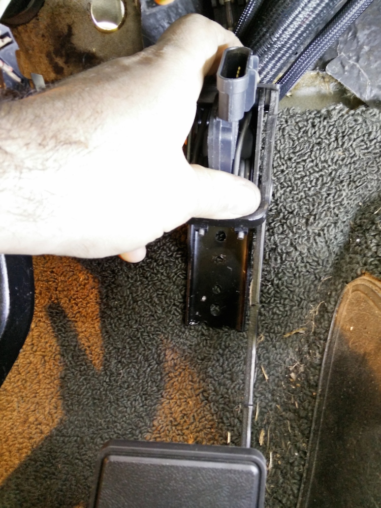
I will drill holes for the pedal and weld a couple of bolts from the backside so that I can just use some nuts to hold the pedal in place.
Andrew
The other, more useful task that I accomplished was finding a place for the Dominator ECU. The ECU is massive and there isn't much room under the dash, so I decided that it can live on the back of the glove box door. I welded some bolts directly to the door and it's pretty sturdy.
The next big task that I got mostly done is the mount for the electronic throttle pedal. The firewall isn't very flat where the pedal is supposed to go, so I had to make some brackets that would give the pedal a nice flat spot to mount.
First, I made a little bracket that bolts to the firewall just below where the old pedal used to pass through the firewall. That hole was used to route all of the ECU wiring.
I welded two 3/8" bolts to the bracket, so tightening them from the engine compartment would be a one man affair.
Next, I made another bracket that bolts to the first bracket and goes down to meet the firewall.
The carpet covers all of it nicely and now I have a solid place where I will mount the gas pedal.
I will drill holes for the pedal and weld a couple of bolts from the backside so that I can just use some nuts to hold the pedal in place.
Andrew