


LS2/E40 C206 Pinout Confusion
I know I'm not the only only having trouble identifying the pins in the C206 connector on the LS2/E40 harness (in my case, 2006 GTO M6). The C206 connector is the large white 26 pin connector that originally connected to the BCM inside the cabin.
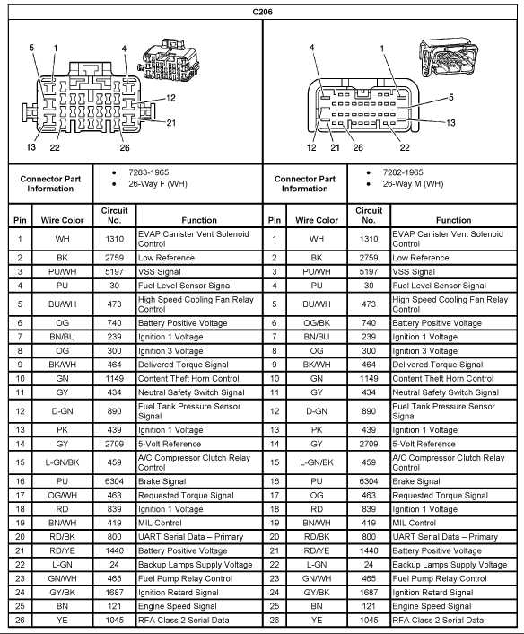
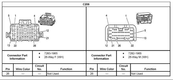
The AllData information, which I've attached below, has two complete and different pinout charts for C206. There isn't any notation signifying their difference(s). Neither matches my C206.
Both of the AllData charts show most pin positions utilized (though some are indicated "Automatic Only") while my C206 has only 11 positions occupied. Four of those 11 are occupied by two wires that loop between two pins, without any splice into the harness. In other words, each of those two wires simply connects one pin position to another.
We're trying to convert these harnesses to standalone and need to properly identify these wires.
Below are the contents of my C206 followed by the two separate AllData diagrams:
Pin 1 - Brown looped to Pin 4*
Pin 2 - Black
Pin 3 - open
Pin 4 - Brown looped to Pin 1*
Pin 5 - Brown w/Black looped to Pin 12*
Pin 6 - open
Pin 7 - Brown w/Blue
Pin 8 - open
Pin 9 - open
Pin 10 - Green
Pin 11 - open
Pin 12 - Brown w/Black looped to Pin 5*
Pin 13 - Pink
Pin 14 - open
Pin 15 - Lt Green w/ Black
Pin 16 - open
Pin 17 - open
Pin 18 - open
Pin 19 - open
Pin 20 - open
Pin 21 - Yellow
Pin 22 - Lt Green
Pin 23 - open
Pin 24 - open
Pin 25 - open
Pin 26 - open
Last edited by TipsyMcStagger; Nov 28, 2017 at 09:25 PM.

Teching In
Joined: Feb 2013
Posts: 9
Likes: 0
I'm in the exact same boat as Tipsy. I have a 2005 GTO LS2 with a 6spd manual. My c206 is wired exactly the same as Tipsy. I, too, am trying to convert this harness to standalone (engine and trans are going into bmw e36 m3). Any info would be greatly appreciated!

On The Tree
Joined: Nov 2014
Posts: 198
Likes: 0
From: Las Vegas, NV
Typically the body harness is not needed for standalone, as you are not controlling power windows, locks, AC, ect with a conversion. The ECM plug pin outs that I attached above is how you wire up a standalone E40 harness.
I didn't realize you switched to the E38/58x. I must have missed that!
Thanks for the input!
Tipsy
Last edited by TipsyMcStagger; May 26, 2019 at 11:23 AM.

On The Tree
Joined: Sep 2012
Posts: 134
Likes: 0
From: New Taxes York
Tipsy is correct....if you give me a few minutes, I'll see which one's I cut from the connector and used.
But that write-up from 4LUX is right on. It's everything needed in a nutshell. Perfect... I'd forgotten all about those!
But that write-up from 4LUX is right on. It's everything needed in a nutshell. Perfect... I'd forgotten all about those!
Trending Topics
Launching!


Joined: Feb 2011
Posts: 250
Likes: 120
From: Raleigh NC
Yes what 4lux said� you shouldn't need anything from that plug in a standalone situation. Just worry about the ECM plugs wiring. Now if you were doing a BCM then that is a different story.
That being said. Obviously your wiring matches the second diagram you posted much closer than the first diagram, so I would go from that as a starting point if you are doing a BCM. Do you have the entire set of diagrams from AllData? I bought the entire set from them when I did my wiring since I am doing a BCM with factory gauges, paddle shift, cruise, etc. If you do have the full set of diagrams and they are in PDF form- do a search of the circuit number. That way the search will bring up every page that has that circuit on it, which makes it way easier to figure out if you need those wires or not. Are 1/4 and 5/12 a twisted pair? If so, those are the high speed communication wires (think of it as a network so the different modules can talk to each other). Why they loop between each other?? You will still need the communications from your ECM that will go to the DLC plug, and if you are not doing a BCM then you will most likely need a resistor at the plug to get the ohms correct.
That being said. Obviously your wiring matches the second diagram you posted much closer than the first diagram, so I would go from that as a starting point if you are doing a BCM. Do you have the entire set of diagrams from AllData? I bought the entire set from them when I did my wiring since I am doing a BCM with factory gauges, paddle shift, cruise, etc. If you do have the full set of diagrams and they are in PDF form- do a search of the circuit number. That way the search will bring up every page that has that circuit on it, which makes it way easier to figure out if you need those wires or not. Are 1/4 and 5/12 a twisted pair? If so, those are the high speed communication wires (think of it as a network so the different modules can talk to each other). Why they loop between each other?? You will still need the communications from your ECM that will go to the DLC plug, and if you are not doing a BCM then you will most likely need a resistor at the plug to get the ohms correct.
LS1 Tech Stories
The Best V8 Stories One Small Block at Time

6 Common C5 Corvette Failures and What's Involved In Repairing Them
Pouria Savadkouei
Retro Modern Bandit Pontiac Trans AM Comes With Burt Reynolds' Autograph
Verdad Gallardo
Top 10 Greatest Cadillac V Series Performance Models Ever, Ranked
Pouria Savadkouei
Top 10 Most Powerful Chevy Trucks Ever Made!

Hennessey's New Supercharged Silverado ZR2 Has 700 HP
Verdad Gallardo
Coachbuilt N2A Anteros Is an LS2-Powered C6 Corvette In Italian Clothes
Verdad Gallardo
Awesome K5 Blazer Restomod Comes With C7 Corvette Power
Verdad Gallardo
10 Camaros You Should Never Buy

10 LS Engine Myths That Refuse to Die
Verdad Gallardo I bought access for the 2006 GTO.
I traced all of the wires from the C206. The results are mostly self explanatory:
Brown loop - CAN Bus - not used
Brown/Black loop - CAN Bus - not used
Pink - merges with other pinks
Brown/Blue - Reverse Light Sensor (needed)
Lt Green - Reverse Light Sensor (needed)
Yellow - reverse lockout (needed)
Black - C3 49 - Low Reference (needed?)
Lt Green/Black - C3 51 - A/C Compressor Clutch Relay Control (needed - I'm retaining A/C)
Dk Green - goes into the horn connector and then continues out into the harness as Black/Red. It continues through to the right coils/injectors and ends up at A/C compressor (needed)
Tipsy
Pin 1 - Brown looped to Pin 4*
Pin 2 - Black
Pin 3 - open
Pin 4 - Brown looped to Pin 1*
Pin 5 - Brown w/Black looped to Pin 12*
Pin 6 - open
Pin 7 - Brown w/Blue
Pin 8 - open
Pin 9 - open
Pin 10 - Dk Green
Pin 11 - open
Pin 12 - Brown w/Black looped to Pin 5*
Pin 13 - Pink
Pin 14 - open
Pin 15 - Lt Green w/ Black
Pin 16 - open
Pin 17 - open
Pin 18 - open
Pin 19 - open
Pin 20 - open
Pin 21 - Yellow
Pin 22 - Lt Green
Pin 23 - open
Pin 24 - open
Pin 25 - open
Pin 26 - open
Brown loop - CAN Bus - not used
Brown/Black loop - CAN Bus - not used
Pink - merges with other pinks
Brown/Blue - Reverse Light Sensor (needed)
Lt Green - Reverse Light Sensor (needed)
Yellow - reverse lockout (needed)
Black - C3 49 - Low Reference (needed?)
Lt Green/Black - C3 51 - A/C Compressor Clutch Relay Control (needed - I'm retaining A/C)
Dk Green - goes into the horn connector and then continues out into the harness as Black/Red. It continues through to the right coils/injectors and ends up at A/C compressor (needed)
Tipsy
Last edited by TipsyMcStagger; May 26, 2019 at 11:25 AM.
On The Tree
Joined: Sep 2012
Posts: 134
Likes: 0
From: New Taxes York
My C206 has (had) 13 wires in it.
My Pin 4 and 12 go to the TCM and are still in the C206 connector, and end there...not connected to anything. I can still get scan data from the TCM.
Pins 1 and 5 are the two wires from C206 that I have tied to the DLC connector harness. I also added the resistor to the back of the DLC connector, but I ran it without one for a year and never had trouble with scanning the ECM\TCM.
Pin 6 (OR\Blk) I have going to the aux. fuse block to power it for some reason.
Pin 9 (YE) and Pin 13 (Pink) I have tied together to a pink 12V source wire in the harness near the ECM. Again, I don't know why but I had to.
Maybe these connections aren't needed, but the two DLC wires are. Why I have the others wired the way I do I can't remember.
Last edited by HwyStarJoe; May 22, 2015 at 05:34 PM.