When you click on links to various merchants on this site and make a purchase, this can result in this site earning a commission. Affiliate programs and affiliations include, but are not limited to, the eBay Partner Network.
Putting in a Tick stage 2 turbo cam and trick flow timing chain dampener. Put the degree wheel on it and it was perfect with stock gears dot to dot. On went a new GM chain.
Used Speedmaster head studs from Jegs and LS9 head gaskets to get the motor going back together.
ICT Billet valley cover with the stock gasket
Waterpump and accessory brackets after a blast and paint, they actually turned out really good.
Another homemade tool, this time a flywheel holder made out of a flat piece of 1/8 plate. Holes are slotted so it can slide back and forth on the starter bolts to engage the teeth on the flexplate.
Fuel system consists of Holley 120lbs injectors in the Edelbrock rails. Holley regulator mounted to a piece of aluminum angle I welded to the back of the intake. -10 feed with a -8 return. The -10 Y'd into -8 at the back of the rails.
I mounted two Walbro 450 in the stock tank. One with a checkvalve which will come on at 5 PSI, triggered by the Dominator ECU. I wish I would've taken more pictures of the pump installation. I just took a flat piece of 16ga steel from the hardware store and used hole saws to make the round plates. Then used riv-nuts for threads.
While the engine was out I re-did the rear shock mounts and cross member. They were at too much of an angle for me, right at 45 degrees. I stood them up to 18 degrees just like the Art Morrison instructions said.
Ran new brake lines throughout the entire car
You can also see where I mounted the engine computer
Turbo oil feed and drain done. Picked up the oil feed from the plate above the oil filter. You can also see the DEI wrap on the exhaust.
Here is my homemade pre-oiler. It's made out of PVC pipe. I used an oil pan drain plug from NAPA for the oil galley plug and drilled and tapped it for 1/8" NPT. Put about 40 psi in it and when I saw pressure on my gauge I cranked the starter over for a bit.
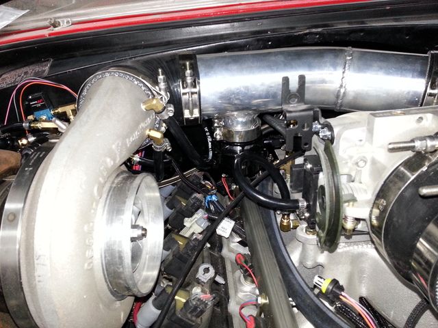
Cold side coming together. Ground the flange off of the compressor outlet to use a slip fit.
3 1/2 inch into and out of the intercooler. I stepped it up to 4" then into the throttle body which is 4 1/2 inch. I thought it would work better that way than to have a big change right at the throttle body. Not sure it will really make a difference but that was my thought process.
Welded a bung in the 4" section for the IAT sensor.
I can't take credit for the idea but I made these out of muffler clamps and old vice grips to put a lip on the aluminum pipes for the silicon joints. It worked very well. It's also a pretty good workout for the forearm...lol
Last edited by squarles67; 12-23-2016 at 04:04 PM.
Great build! I can't say that I am a fan of the boost control plumbing. I'd use a combination of that NiCopp line and AN fittings and PTFE flexible hose. You might also want to install a AIT sensor before the intercooler for logging.
I'm not particularly fond of how the boost control plumbing turned out either and I'll likely change it before too long. I just want to get it running for now.
Good idea on the extra IAT sensor, it's crazy the amount of data that the dominator can handle. I may add a sensor to the intercooler water temp as well.
Another homemade tool, this time a flywheel holder made out of a flat piece of 1/8 plate. Holes are slotted so it can slide back and forth on the starter bolts to engage the teeth on the flexplate.


 12-18-2016 | 05:52 PM