
L83 Gen V Swap into 1956 Buick Special
 10-17-2017, 01:27 PM
#61

Ok, thank you! I should be good then. my engine / trans / ecu were all out of the same vehicle. I have another 6l80e swap going on right now too with an engine / transmission out of a 2014 Silverado, and ecu out of a 2015 Silverado. think that will give me trouble?
 10-17-2017, 03:49 PM
#63

You can research to see if the ECU was used in 2014 and 2015. If it was then all you would have to do is MAYBE reprogram your 2015 ECM with the 2014 program. However it might work as is. One way to find out.
 10-30-2017, 11:45 AM
#65
Wiring question- maybe someone can help.
I have everything just about finished, but one think I'm having trouble with is the TCC switch. I am familiar with the Gen III LS1 where there is a constant key on signal and the TCC switch sends power back to the computer when the brake is NOT applied.
However, for this gen V setup, there appears to be three wires going from ecu to TCC and three wires going from the body control module to the TCC. any insight as to wiring this for standalone? I have a universal style, two prong, TCC switch ready to go but not sure how to integrate this..
Please help! thanks
10-30-2017, 04:36 PM
#66
After some research it looks like maybe I use a single pole double throw relay that sends ground to the ECM when the brake is applied and key on power to the ECM when the brake is not applied. and then of course my brake lights will be a separate circuit.
Does this sound roughly correct? will try to update with a diagram to show what I mean
Does this sound roughly correct? will try to update with a diagram to show what I mean
 10-30-2017, 11:35 PM
#68
So if I understand this correctly, with my double throw relay, when the brake pedal is in its natural resting state this will result in 5359 and 5361 being connected. when brake pedal is applied, 5361 and 5360 will then be connected?
yeah?
This may help:
5359: Brake apply sensor supply voltage
5360: Brake apply sensor low reference
5361: Brake apply sensor signal
Another way of saying what I'm asking is- when no brakes, the sensor signal gets voltage. when yes brakes, sensor signal gets low reference
yeah?
This may help:
5359: Brake apply sensor supply voltage
5360: Brake apply sensor low reference
5361: Brake apply sensor signal
Another way of saying what I'm asking is- when no brakes, the sensor signal gets voltage. when yes brakes, sensor signal gets low reference
11-08-2017, 10:59 PM
#69
So to answer my own question, no that's not how you hook it up.
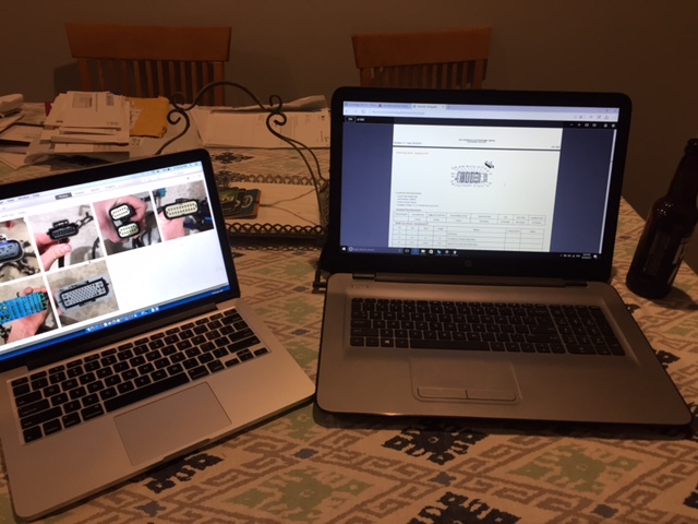
This 2014 setup uses a brake pedal position sensor thats a resistor. rather than binary, it sent signal and is integrated into the body control manual wiring and yuck idk how I'm going to wire it. I bought the actual sensor, here are pics. I'm hoping to use hptuners to change things around to use the "old school" binary TCC switch.
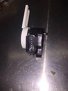
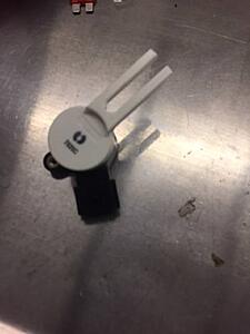
This 2014 setup uses a brake pedal position sensor thats a resistor. rather than binary, it sent signal and is integrated into the body control manual wiring and yuck idk how I'm going to wire it. I bought the actual sensor, here are pics. I'm hoping to use hptuners to change things around to use the "old school" binary TCC switch.

 11-09-2017, 09:34 PM
#70
You do not need the Brake Pedal Sensor. Just wire 12volts brakes applied to X1 Pin 57 Wht/Blu. It is vital you do this.
Wiring question- maybe someone can help.
I have everything just about finished, but one think I'm having trouble with is the TCC switch. I am familiar with the Gen III LS1 where there is a constant key on signal and the TCC switch sends power back to the computer when the brake is NOT applied.
However, for this gen V setup, there appears to be three wires going from ecu to TCC and three wires going from the body control module to the TCC. any insight as to wiring this for standalone? I have a universal style, two prong, TCC switch ready to go but not sure how to integrate this..
Please help! thanks
I have everything just about finished, but one think I'm having trouble with is the TCC switch. I am familiar with the Gen III LS1 where there is a constant key on signal and the TCC switch sends power back to the computer when the brake is NOT applied.
However, for this gen V setup, there appears to be three wires going from ecu to TCC and three wires going from the body control module to the TCC. any insight as to wiring this for standalone? I have a universal style, two prong, TCC switch ready to go but not sure how to integrate this..
Please help! thanks
11-16-2017, 05:00 PM
#71
And to be clear that is 12v brake applied? rather than brakes not applied like the 98-02 TCC switched setups worked?
Do I need to adjust any tuning?
Is full 12v to pin 57 effectively telling the computer 100% brake application?
11-16-2017, 07:36 PM
#72
Yes, hook to hot when brakes applied. This tells the ECU and TCM brakes applied. The bcm sends 12 volts to this wire when the brake sensor is being applied. If you don't do this the transmission will be very un happy and you will also have loss of engine power.
11-17-2017, 11:40 AM
#73
Great, thank you!!
11-17-2017, 10:47 PM
#74
Teching In

Join Date: Jun 2011
Posts: 26
Likes: 0
Received 0 Likes
on
0 Posts

Wow, I've go 2 gen 4 swaps going that had the brake pedal position sensor, one a 5.3 and one a 6.2 both will have bcm' scan I get away with using simple 12v switched to tell ecu and TCM the brakes are applied?
11-17-2017, 10:58 PM
#75
Yep, the gen IV's are the same. Connector X1 pin 9 gets 12v brake applied. You can also use a scanner to double check your brake signal. The 2012 and newer Gen IV's went to a brake pedal sensor. The earlier models used a brake switch. The BCM sees an exact brake pedal position and then shoots out a 12v signal to the GM ECU. This is for the TCM to know brakes applied.
11-18-2017, 02:21 AM
#76

This is way over my head. LOL
The following users liked this post:
BigBlockLover454 (05-04-2020)
11-18-2017, 02:22 AM
#77
Vannatta20,
Do you plan on any GenV swap threads?
Do you plan on any GenV swap threads?
11-18-2017, 08:28 AM
#78

curious why the brake position sensor sends the info to the ecm as shown in the diagram OP posted above...redundancy? with there be a problem if the two don't match? (the one coming from the position sensor and the 12v coming from the bcm) apparently not if this works for vannatta20
11-22-2017, 04:12 PM
#80
Got the brake wiring finished, but heres another weird issue: alternator does not charge when small gauge 2 wire connector is plugged in. But DOES charge when this connector is unhooked. goes right to 13.5 volts.... but is completely dead when plugged normally... any thoughts?