When you click on links to various merchants on this site and make a purchase, this can result in this site earning a commission. Affiliate programs and affiliations include, but are not limited to, the eBay Partner Network.
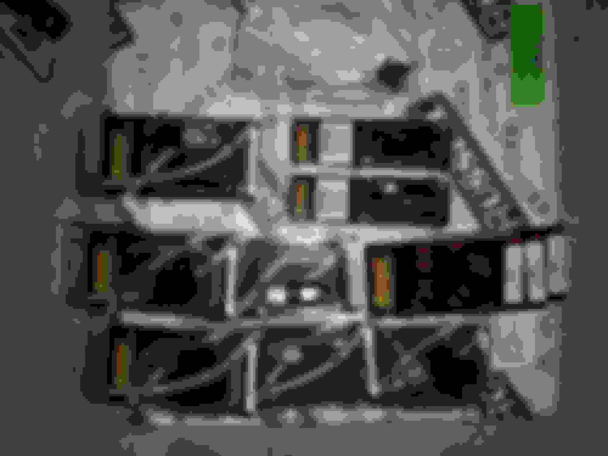
Switching gears a little bit, I got a bunch of trans parts cleaned up during my lunch today. They will still need to be wiped off once more with a clean lint free rag before final assembly, but these have all been inspected, got all the clutch material / rubber build up off of and have been reworked so they are ready for the bushings. I had to do some mixing and matching between the 2 4L80's I have to get a good set of hard parts, but it will probably end up saving me money if I can get enough parts between the 2 transmissions. I already have $100 worth of parts that I would have had to replace/buy if I didn't have the spare trans sitting around.
On to some pics. Here's the forward clutch pressure plate that has been surfaced and cross-hatched for a good bite on the clutches.Kind of hard to pick up the cross-hatch with the lighting.
Here's the forward clutch hub. This is the one from the spare parts 4L80. The original one had the tangs on the outer portion all worn down and was beyond useable.
Here's the forward clutch housing. I was slightly concerned with the inner bore where the sealing rings sit as there was some wear, but I couldn't feel it with my finger or a pick. I touched it up with some fine grit sand paper and it polished right out in just a few swipes. Still needs a final once over before final assembly, but the large chunks of crap are gone.
Here's the direct clutch housing. I almost used the one from the spare trans as it was actually slightly cleaner, but the bore that seals to the center support was badly grooved beyond my comfort level for rework. The band surface on both was still pristine with no visible wear. I will be dual feeding this trans, so the sealing ring will be left out.
I followed a similar procedure with the direct clutch housing pressure / backing plate that I did on the forward clutch backing plate:
I also cleaned and modified the center support and over-run clutch housing.
All the cleaned/inspected parts in my make-shift clean room awaiting further assembly. I will still need to set the clearances on the clutch packs and press in the new bushings, but since I'm waiting on engine parts, I figured I would switch back to the trans for a bit. All parts have been treated with a light coat of trans fluid to prevent flash rusting after the mineral spirits wash and spray down with Red Brake Clean - first time I've ever used the red can and it seemed like it is much stronger than the green can.
I was able to get enough parts cleaned and bushings installed to start setting up the rear thrust on the trans. There's not a lot of videos out there on how to do this, but essentially what you need to do is assemble the trans up through the center support including the snap ring and all thrust washers / and both 3 piece bearings, then pry up on the parking pawl gear through the opening in the case to load and unload the rear assembly. My dial indicator screws into the pump to case bolt holes perfectly and allows me to indicate off the rear shaft.
Since I am rollerizing the rear to case, I measured the thickness of the case thrust washer and selective washer. I got a value of 0.155". The TH350 pump bearing measures out to be 0.139-0.1395, so I selected the 0.015" shim from my shim kit as a starting point. My initial reading was 0.075" ! I figured something was probably not correct here and I found out I left out a 3 piece bearing and a thrust washer.
Once those had been corrected, I re-measured the clearance and found it to be 0.012". At this point, you must disassemble down to the case again and change the shims to get the appropriate clearance. In this case 0.002-0.010" is the range I'm shooting for with closer to the nominal of 0.006" if possible.
I used the 0.020" shim next as it was the next thickest and my clearance measurement came out to be 0.010", so I was questioning my prior measurement at that point. Just for kicks, I decided to throw in the 0.015" and 0.010" shims to see if that moved the clearance down by the appropriate 0.005". Bingo! I landed at almost perfectly nominal clearance. I wanted to double check this so I tore it down and reassembled it and was able to replicate my measurement within what I would call the error of the indicator.
Hopefully my flat top pistons and gen 4 rods arrive tomorrow so I can drop them off at the machine shop for balancing of the rotating assembly.
I am considering changing up the cam choice for the engine build as well since I am now going to be nearly 11:1 compression and can take advantage of some higher lift with the better flowing 799 heads. The summit pro ls stage 3 cam seems to be more of what I'm looking for and still a fairly reasonable price. 231/242 @ 0.050, 0.600/0.600 lift on a 113+3 LSA. This is pretty close to the howards hydraulic roller I was running in the 383 with only 10:1 compression (233/241 @0.050 0.530/0.545 on a 112 and did very well with a 3000 stall). Doing a calculation on my SCR and DCR though, I'm wondering if this cam will have too high of a DCR for the street - 8.95:1 DCR with an IVC at 0.050 of 46 degrees. Luckily here in Michigan we have 93 octane instead of the 91 found elsewhere, but am I wrong to question this DCR for pump gas? If I use a stock LS2 cam spec, it comes out to >9:1 DCR and it gets away with 93/91 octane just fine with an IVC @ 0.050 of 42 degrees.
I am considering changing up the cam choice for the engine build as well since I am now going to be nearly 11:1 compression and can take advantage of some higher lift with the better flowing 799 heads. The summit pro ls stage 3 cam seems to be more of what I'm looking for and still a fairly reasonable price. 231/242 @ 0.050, 0.600/0.600 lift on a 113+3 LSA. This is pretty close to the howards hydraulic roller I was running in the 383 with only 10:1 compression (233/241 @0.050 0.530/0.545 on a 112 and did very well with a 3000 stall). Doing a calculation on my SCR and DCR though, I'm wondering if this cam will have too high of a DCR for the street - 8.95:1 DCR with an IVC at 0.050 of 46 degrees. Luckily here in Michigan we have 93 octane instead of the 91 found elsewhere, but am I wrong to question this DCR for pump gas? If I use a stock LS2 cam spec, it comes out to >9:1 DCR and it gets away with 93/91 octane just fine with an IVC @ 0.050 of 42 degrees.
How did you calculate the DCR at .050 or .006? You're supposed to use the .006 number when calculating. The online calculators seem to be much different depending on which one you use. I've read if using the .050 numbers that come on the cam card when calculating the IVC... you're supposed to add 15 degrees to that calculated IVC number. On my 231/234 .629" .615" 111+2 the intake closes at 44.5* With a static of 11.4 running 93 octane and 27* of total advance I'm not seeing any knock. You at 46* closing should be ok. I've read a lot about DCR and some cam grinders like Kip from Cam Motion says not to worry about DCR. The more you read different opinions on the subject the more confusing it gets lol.
Yes, the calculator I found used the 0.050 number, not the 0.006 number. I think I might reach out to my powertrain friends at work (I have good connections with people in the engine development/testing/analysis group) about this as well, but I don't think I'm going to worry too much about it.
You can see my ultra high dollar clearance checking tools sitting on top of the intake manifold where the highest points are. I figured I needed a super high level of precision for this, so I broke out the calipers to check how many thousandths of clearance I had:
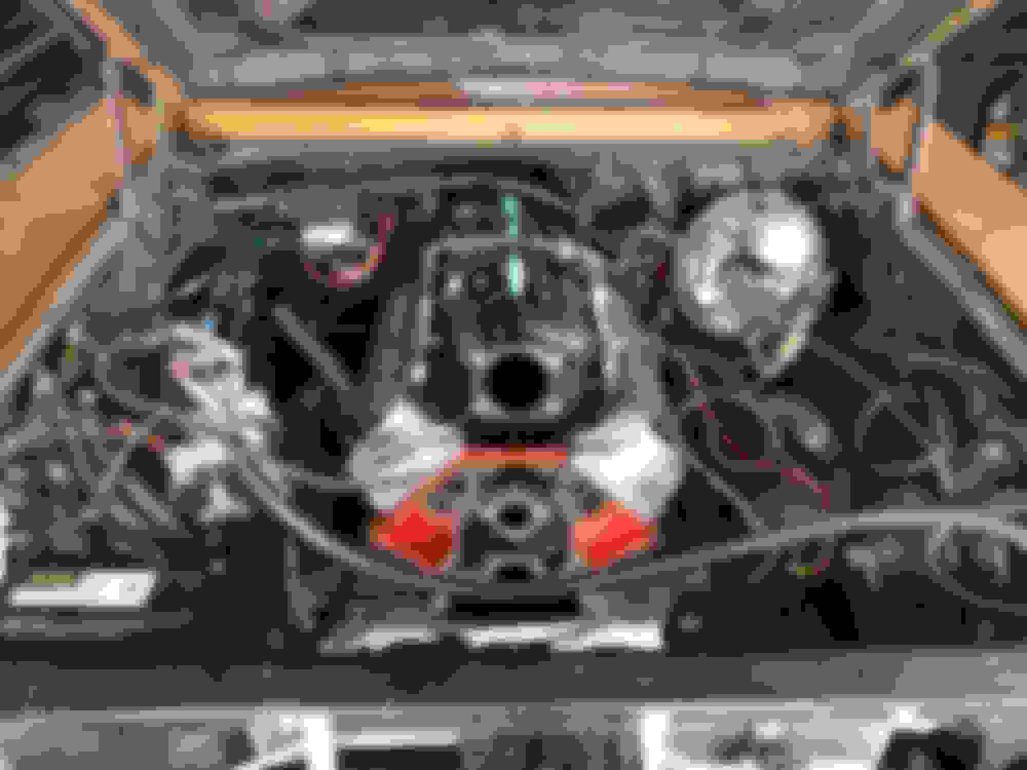
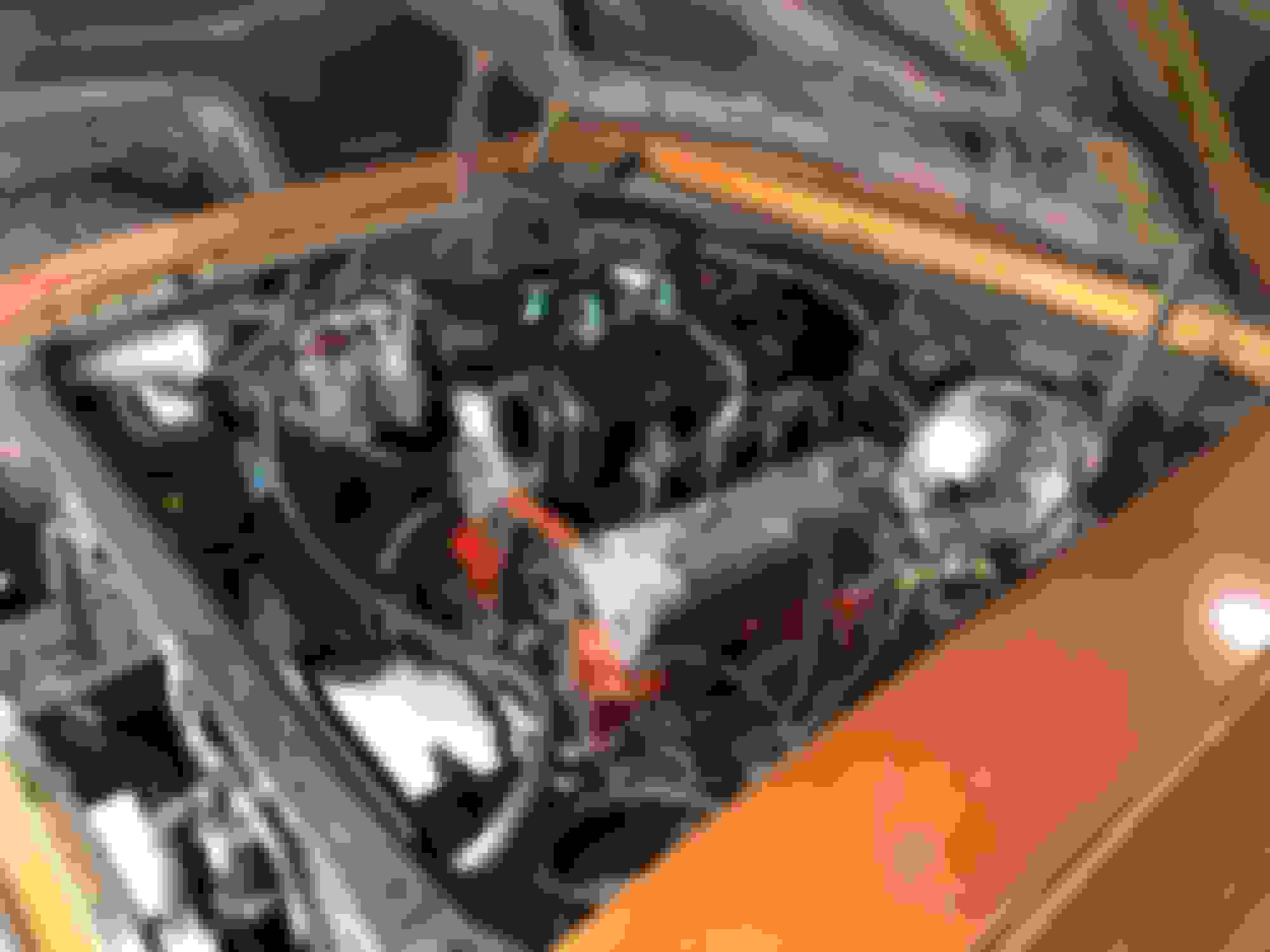
This is all with the stock hood - no cowl or cheater opening or anything like that. Total sleeper. This actually gives me more clearance to the hood than the 14" air cleaner on the 383 did. I had to bend some of the hood bracing to allow it to fit and even then I only had 1/2" clearance. I'm still not sure how the throttle body will interface with the hood - that could throw my whole plan out the window, but I know that the NBS truck intake fits without issue under the stock hood, so I can always fall back on that if this doesn't work out. I wanted to take a few more measurements / clearance checks to make sure I wasn't going to have any issues with the steering hitting the oil pan. I apparently don't have a pic of full lock to the left, but the clearance was the same or better than full lock to the right. This is at full droop too, so the grease zerk will rotate down when the weight of the car is compressing the suspension and clearance will only improve.
Yep you have more sump clearance than mine by far. I had to drop mine in and bolt the mounts on the engine in place. The first time my 6.0 went in it stayed.
Looking back through my pics, I found the clearance at full lock left between the tie-rod end and oil pan. Just for consistency, I'll put both full lock left and full lock right in this post for future reference.
Small update today, cam has been ordered along with a cam bearing install tool, LS2 timing chain, LS2 style chain dampener, 4' non-adjustable piston ring compressor and the MAP hold-down clip. I looked at the cam bearings closer after cleaning the block, and they were indeed bad. (the old adage of if you look at your cam bearings they will be bad applies here....) The bottoms of cam bearings 2-4 were showing copper in an un-even pattern and had a very rough texture to them. Could also see what appeared to be a seam opening up on one of them. I will be running Clevite bearings throughout - the machine shop that is balancing my rotating assembly wouldn't warranty any of their work if I was going to re-use my old bearings, and they had a good deal on the Clevite's when buying through them.
New part numbers to add to the build list:
Camshaft: SUM-8708 (Summit Pro LS Stage 3 Cam - 231/242 @0.050, 0.600/0.600 on 113+3 LSA)
Cam bearing install tool: SUM-900131
LS2 Timing Chain: SUM-143012
Piston Ring Compressor: SUM-904000
Timing Chain Dampener Kit: TFS-K30675600
MAP Sensor Clip: ADO-12617897
I decided to have a somewhat local company do my wiring harness for me - they are about an hour and a half away so, I decided to hand deliver the harness rather than pay for shipping 2 ways. I could do this myself and I have been back and forth about it for the past few weeks, but after weighing the cost of the crimpers, the fuse panel, fuses, relays, extra wire, mesh covering I wanted, and the different connectors I would need, the cost was creeping up there close to what this company was charging to do it all for me. They are basically going to be replacing most of the wires in it with higher quality wire, changing the injector plugs to the EV6/USCar style that my injectors need, deleting all the emissions stuff, incorporating a busmann fuse panel, and setting up the gauge outputs to work with my Autometer gauges, and lengthening/shortening where necessary to allow me to mount the PCM in my preferred spot. Since I am off today, I drove the harness over there and talked with them for quite a while about the changes I wanted and I even got to see a few harnesses they had in progress at various stages of completion. I'm also getting new O2's and a new LS7/LS3 style MAF sensor. Here is what the harness will look like when done:
Low mount AC, L99 water pump, Nick Williams 92mm Cable TB
Alright, enough with the generic updates and on to some real progress on the car.
I ordered my new water pump and low mount AC brackets along with a Sanden 7176 / SD7 (not really sure what the difference is or if there even is a difference between the two) and a throttle cable that I will either have to modify or return / exchange for a different unit. What are you cable throttle body guys using for a throttle cable? I can't seem to find a good part number or even an application (I know it's probably been discussed a million times, but my extensive searching over the past month hasn't yielded any info - keywords are probably different enough that it isn't bringing it up for me so if anyone has a part number of what they used in a 1st or 2nd gen Camaro or 3rd / 4th gen Nova, I'd appreciate it.
I ended up using a Holley low mount bracket (20-159) in the long belt alignment configuration to match my truck balancer spacing since I will be using the truck accessories and an L99 Camaro water pump (19207665). The Holley bracket is quite a nice piece and allows me to use the stock AC belt tensioner which saves me some money as this project has had significant scope creep as all my Nova projects seem to have... This bracket does require you to slightly modify the Sanden compressor by pressing in the bushings in the rear mounting ears to fit in the bracket.
The back of the compressor clears the frame rails with my engine mount configuration and the combination of the long belt alignment for the truck balancer.
Plenty of clearance to the steering links.
I was slightly concerned with doing the low mount AC that I wasn't going to have space to route my trans cooler lines, but since I won't have the fuel line coming up the rail on this side under the control arm, I will be able to tuck my lines in this routing and then have them dive back down towards the block after the engine mount. Still need to confirm header clearance with this routing, but I'm hopeful that it will clear.
Here's my L99 Camaro water pump and Nick Williams 92mm cable throttle body. My intake manifold did not come with bolts for the throttle body, and a quick online search showed that the stock size is M6x1.00 x 25mm long or somewhere close to that. The hardware store only had M6x1.00 x 30mm long in SHCS, so I picked up 4 of those and confirmed that they are indeed slightly too long for the Nick Williams cable throttle body to this manifold. I'll just trim the end by 5mm or so to get them the correct length. The other thing I need to figure out is the upper and lower radiator hoses. Looks like Mary Pozzi's 73 Camaro uses or used a similar water pump and radiator as I am, and the frame section is very similar to what she had with the stock front frame section, but I can't seem to find what part numbers they used for this configuration. It's about 16" from WP outlet to radiator inlet, the depth is about 9" and hose ID should be about 1.25"
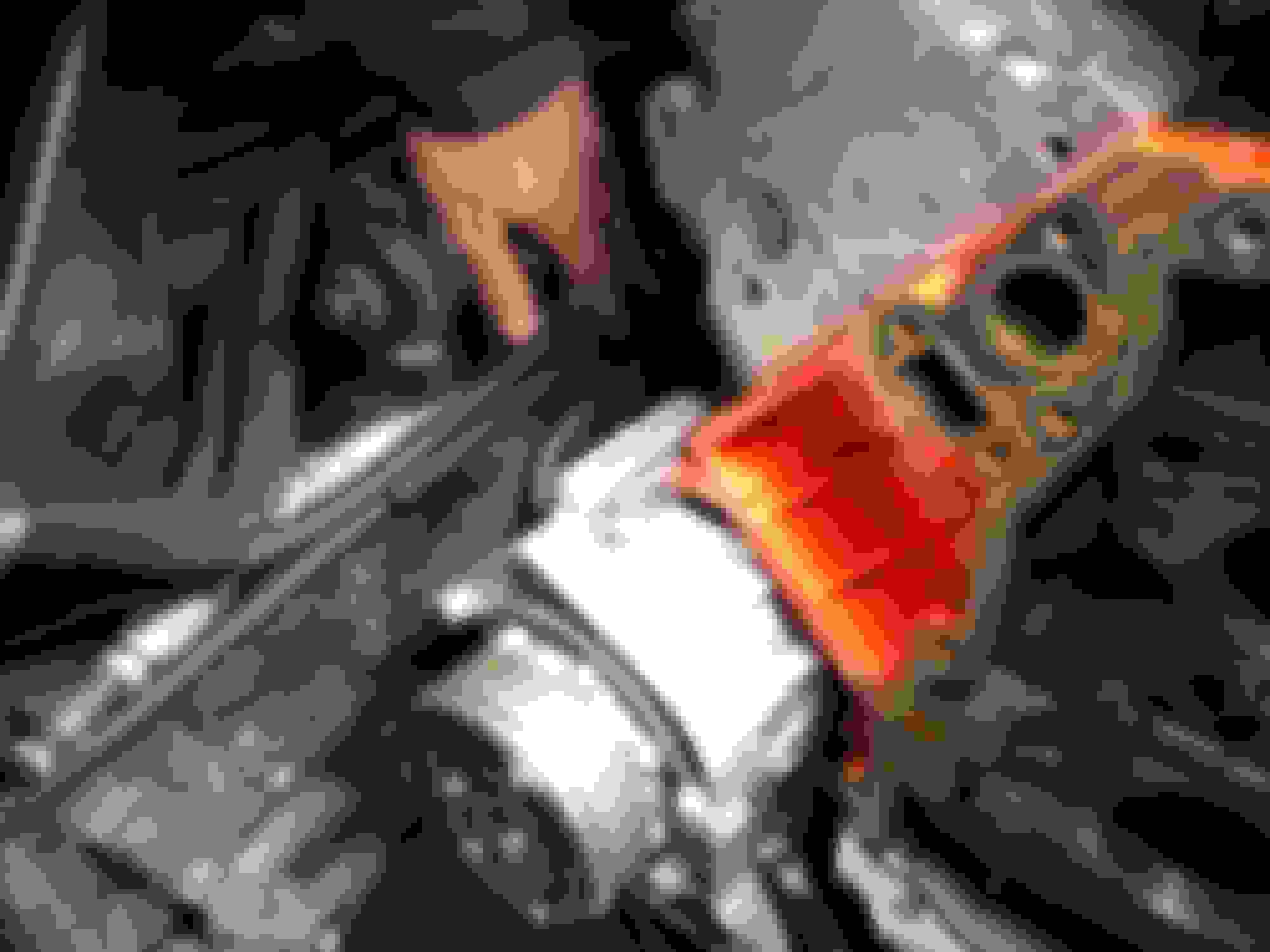
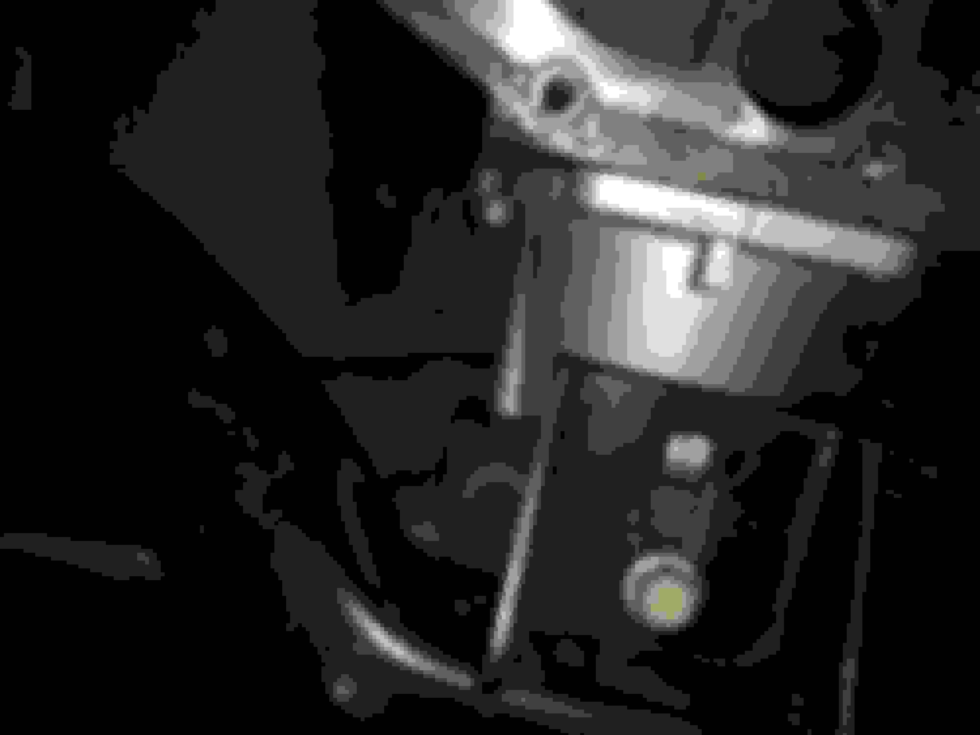
This was my next issue - the heater hose outlets on the L99 pump are too close to the upper control arm to just use a hose on them. The clearance is just over 1", so I'm not sure even the molded bent hoses (80416 & 80406) would fit here without contacting the upper control arm. Looks like I'm going to be pulling the tubes and tapping it for 1/2 & 3/8 NPT to run either a 90deg or 45deg fitting.
The next thing on my list is figuring out which side I'm going to have my cold air intake routed to. I'd like to retain the battery in the stock location for simplicity and cost purposes - battery relocation will add another $250-300, but would allow a bigger, better spot for the filter.
Depending on your accelerator pedal... the V6 Silverado truck cable (99-02) may be a good option. It's made to fit the GAP throttle bracket and fit's the NW TB perfect. It has a grommet that secures into the firewall with what looks like... I'm guessing a 1" hole.
Yeah the Nick Williams 92mm mounts perfect to the TBSS with M6 x 1.00 x 25 bolts.
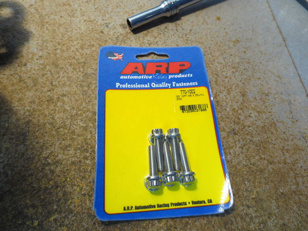
I bought the sweet looking ARP 12pt bolts for $25 to mount my NW/TBSS. Just installed a NX plate system (longer bolts) and now these pretty bolts are just sitting on my workbench lol
I was able to figure out my radiator hoses using some bent household wiring I had laying around from finishing my basement and took that to Advance to match up with some hoses. I found 2 that were almost a perfect fit.
upper hose: Dayco 71703
lower hose: Dayco 72233
The lower hose looks almost exactly like a Gen 1 SBC lower hose. I need to trim a small amount off both ends to get the slight kink out of the lower portion and rotate it further away from the frame.
The upper hose needed a fair amount trimmed off each end, but the general shape was right.
Also got my throttle cable figured out. The throttle cable I ordered was from an early 2000s truck with a 5.3L V8 with cable throttle body. Just needed to open up the hole in my firewall from 1/2" to 5/8" and it snapped right in. It can be seen in the above photo laying over the intake manifold and attaching to the throttle body. The gas pedal end was nearly identical to my factory cable so it clipped right into the original mounting hole in the gas pedal arm.
Throttle cable: Pioneer Automotive CA-9049
Last edited by Nova1978; Jan 4, 2021 at 01:23 PM.
Reason: forgot to add update on throttle cable
To get the 4L80 to bolt in, I needed to decide which way I wanted to go with the crossmember. No one really makes a "bolt-in" crossmember for the 4th gen Nova with a 4L80. I believe there is one or two on the market, but my research showed it required some modification to fit properly. I had already drilled new holes in the subframe from when the 200-4r was in the car that were a good 6" further back from the original TH350 holes, and I needed a few more inches rearward for the 4L80 (~3.25" is what my measurements came out to). My dad came down while I was off work and offered to cut and weld up the original crossmember to accommodate the 4L80.
And here it is with the mockup 4L80 trans (bare case so it's a lot easier to maneuver) sitting on and bolted to the crossmember:
Plenty of clearance around the tail shaft housing:
On the driver side I have lots of clearance to the floorpan, which I wasn't worried about this side:
The passenger side is tight, also expected and I will definitely need to use the banjo bolt to -6AN style trans fittings. There simply isn't enough room to use a 90* -6AN fitting in this trans tunnel without some serious mods.
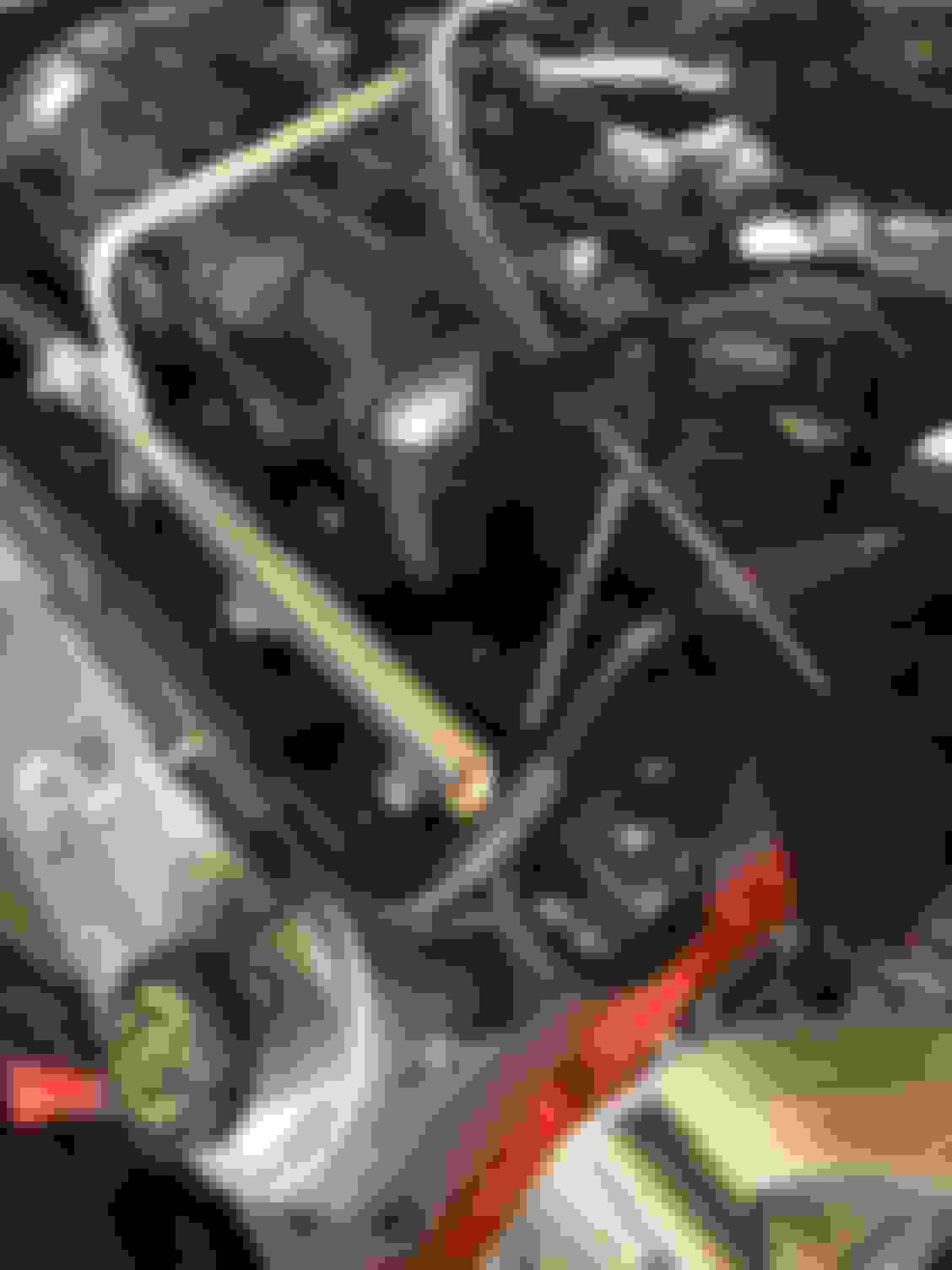
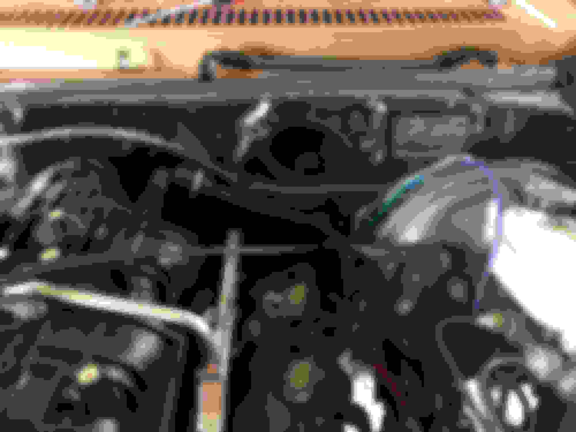
After buttoning up the trans mockup, I decided to take a go at the PCV and brake booster lines. I wanted to have a clean, tight routing for the lines, and I had lots of the hard plastic PCV tubing left over from the 2 NBS intake manifolds I had so I started mocking up the different bends and found that you can remove the "hard line" from the 90* elbow and then re-insert another section of tube. This worked out very well for the quick connect type fitting that I believe is used for an evap solenoid on the NNBS / TBSS applications. This line is hooked up to the LS6 valley cover with built in PCV. My understanding is that this needs to be connected to the manifold behind the throttle body so it sees a lower pressure. The valve cover hose goes to the port on the throttle body which opens in front of the throttle body where it sees a higher pressure and it needs to be metered air, which this location is. The way I see it, the valley cover port is the so-called clean side and it is where clean, filtered and metered air enters the crankcase. The port on the LS6 valley cover is where air leaves the crankcase and gets drawn into the manifold. To get a net flow to occur, you need a pressure differential to drive that flow. Pressure is dropping across the intake from where it enters the filter at approximately atmospheric pressure all the way to the cylinder where the lowest pressure occurs - thus the air pump nature of the engine. Ok, physics / engineering lesson done.
The astute reader/view will also notice my new MAP sensor retainer clip in the below photos.
Similarly, on the brake booster side, I wanted the line to have a neat and clean routing with it tucked tight to the firewall to give clearance to the valve cover in the event of needing to service the rockers. I again used part of the hard plastic PCV hose from the spare intakes I had and I found one section that gave the S bend I was looking for
Next up on the list is the block off plug for the original PCV port in the driver side valve cover, the L99 belt tensioner, and then figuring out the routing for my heater hoses and AC lines. Wiring harness should be done within the next week or so, and the rest of my rotating assembly was dropped off at the machine shop on Monday. Hopefully all the pistons check out and I can pick that all up next week too so the engine build can progress. Trans rebuild is at a standstill until I hear back on my pump. I decided to send it out to be reconditioned because I wasn't comfortable with the state of the gears & the gear pocket.
More parts are trickling in, so here is another update. I had been wanting to do a battery relocation to the rear for a long time, but didn't want to piece together a kit. I found a company out west that builds these kits and uses pretty high quality components all OFC wire with thick coverings, thick adhesive lined heat shrink, 2x 200 amp breakers with manual disconnect, and the Morosso 74051 battery box.
I was hoping to use my current Group 78 battery, but this box just will not accommodate the top post style cable ends on a side terminal battery. With the battery centered in the box, I only had 1/2" between the box and the terminals, and I needed at least 3/4". I didn't even think twice about this battery not having the top posts when I got it 4 years ago as I didn't have top post style cable ends and didn't think I would have a need to have them. Yes, I could have cut off the cable ends on my brand new kit and crimped on the side terminal ends, but I didn't want to cut off the nicely crimped and heat shrinked ends, plus routing the cables through the box for how I wanted them to be just wasn't going to work. access to the side terminals is limited at best, and I don't want to be disassembling the box if I have to replace the battery.
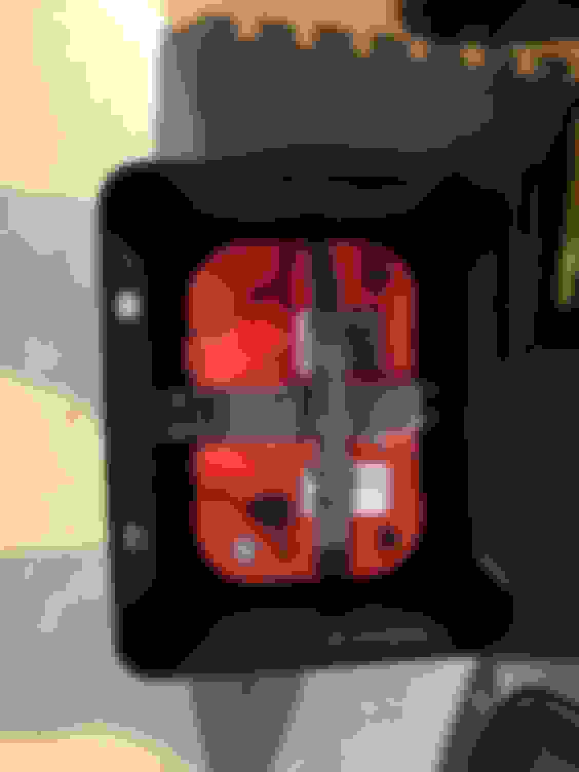
My solution was to upgrade from the FLA battery to a more modern AGM style battery. Optima 34/78 that has the same CA & CCA my FLA did, but hopefully doesn't leak like it did. I was able to get a discount on it through one of the parts stores and they had free next day shipping, so it was priced similarly to their brand AGM but this has higher CCA. Hopefully this is enough to start my 11:1 LQ4...
The sticker also shows it was just born last month, so it's practically brand new!
Much better fit in the Morosso battery box. I can now hook up my cables to the top post and have them run out the long side to where my circuit breakers will be mounted.
Here's what the circuit breaker mounting will look like:
Keeping with the electrical update theme, all my research with the NBS trucks and electric fans has tipped the scales to upgrading to the 130/145 amp larger alternator since I will be running dual fans, and I have A/C. I picked this one up from Summit that came with a dyne sheet. This one cranks out 60-65amps at idle and hit 165amps at 6000 rpm. I also got my L99 tensioner in (part number 19311311) and the idler pulley relocation bracket (ICB-551353).
Next I was browsing the fuel fittings and trying to iron out which ones I needed and trying to minimize the soft line I was going to have - I want to keep hardline where I can. I picked up a fuel rail 3/8 quick connect to -6an adapter (part number 640853) to adapt my fuel rail to AN. My first exposure to AN fittings was with the trans cooler lines I had for my 200-4r and it made me a big fan.
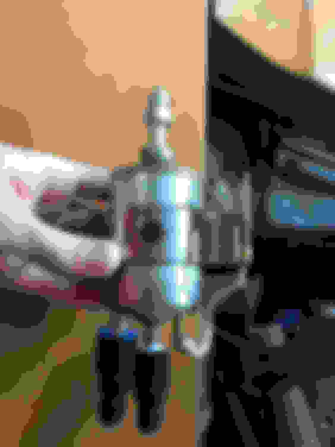
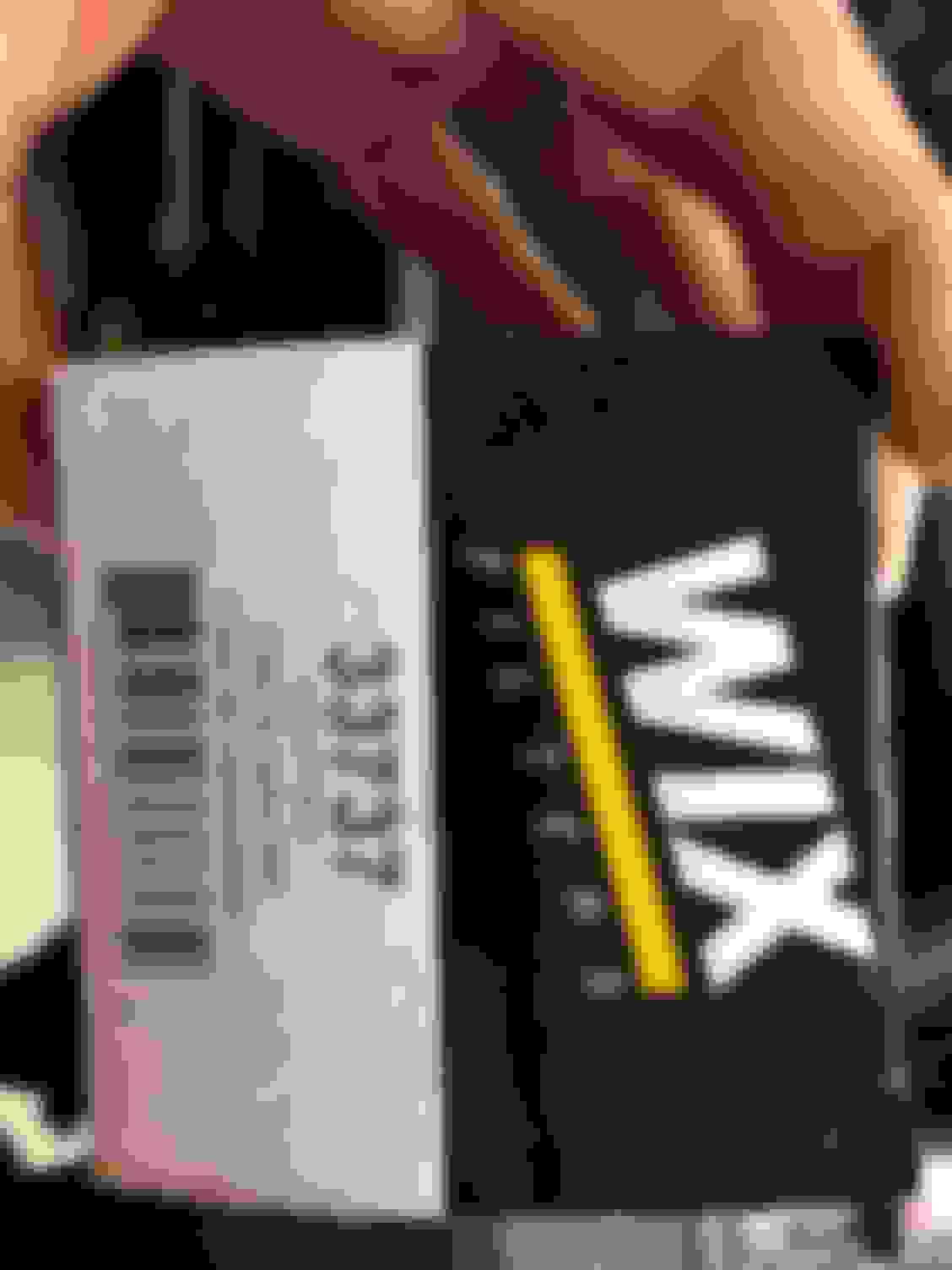
Next was setting up my WIX 33737 fuel filter with the quick connect to AN fitting on the outlet side (part number 640940) and 2 more quick connect to -6AN fittings on the inlet and return side (inlet is outboard and is 3/8", the return is in the center and is 5/16"). Part numbers 640853 and 640863 respectively.
The rest of my AN fittings and the 3/8 hard line I will be using for my tank to regulator and regulator to firewall lines with part numbers for future reference.
Here is one of the last pieces of the puzzle to make the LS6 PCV valley cover work correctly. With the PCV relocated to the valley cover, there is no longer a need to have a PCV valve in the driver valve cover, and GM makes a plug specifically for that spot so you don't have to buy a new valve cover or cap off the old PCV valve or cobble something together. This simply presses into the spot where the old PCV valve was to block off that hole. Part number 12568011.
The rest of my AN fittings and the 3/8 hard line I will be using for my tank to regulator and regulator to firewall lines with part numbers for future reference.
So you're talking about the Corvette filter/regulator correct... and not adding a second regulator?
Retro Modern Bandit Pontiac Trans AM Comes With Burt Reynolds' Autograph
Slideshow: A modern Camaro transformed into a retro icon, this limited-run "Bandit" build blends nostalgia with brute force in a way few revivals manage.
Top 10 Greatest Cadillac V Series Performance Models Ever, Ranked
Slideshow: Cadillac didn't just crash the high-performance luxury vehicle party, it showed up loud, supercharged, and occasionally a little unhinged...
Coachbuilt N2A Anteros Is an LS2-Powered C6 Corvette In Italian Clothes
Slideshow: A one-off sports car that looks like a vintage Italian exotic-but hides a C6 Corvette underneath-just sold for the price of a new mid-engine Corvette.