Madaguy 1955 Nomad Build
#81
Ryan did you watch the recent build with @Summitracing and Robby Layton on Youtube where the built up a rusty 57 Chevy Belair and then drove it across the country?
When I first saw that car my instinct says that car needs to be scrapped. Then I thought of you and the Nomad, and I'm like nope, you can patch just about anything back together with enough time, skill, and patience.
They were doing temporary body and floor repairs using self tappers and license plates lmao.
The following 2 users liked this post by Mr. Black:
nleming (07-11-2023), ryeguy2006a (07-12-2023)
#82
Nice work you been doing just curious but how do you like the Everlast MTS 225. I have an Everlast power tig 250 and a separate mig welder but was thinking of getting the same 225 Lightning multi process unit as yourself and sell my current welders to free up some space.
The following users liked this post:
ryeguy2006a (08-15-2023)
#83
Thread Starter
Joined: Apr 2012
Posts: 2,032
Likes: 594
From: Ruckersville, VA
Steve, I didn't see that but I'd like to check it out. Sounds a lot like the build that David Newbern did for Hot Rod Power tour. I used my fair share of self tappers, but only to hold a panel in place or pull two pieces nice and flush. I wouldn't use them to hold something in place and drive it! 
Kevin, I love this welder. It took a little getting used to moving from my Miller 135 that had 1-10 on wire speed and amperage. This welder has the IPM (inch per minute) and actual voltage. I've also used the DC TIG a few times, and for my first time it wasn't as bad as I thought to get the hang of. I still need a ton of practice, but I'm definitely improving. Huge reason for the new weld cart is so it can hold two tanks; one 75/25 argon/c02 and one 100% argon. I bought mine last year during black Friday and they offered free shipping and a discount on the welder and a few extras I got. It comes with a 25 Mig gun, but that's for heavy metal. I bought the 15 Mig gun which is meant for smaller metal like what I'll mostly use it for.

Kevin, I love this welder. It took a little getting used to moving from my Miller 135 that had 1-10 on wire speed and amperage. This welder has the IPM (inch per minute) and actual voltage. I've also used the DC TIG a few times, and for my first time it wasn't as bad as I thought to get the hang of. I still need a ton of practice, but I'm definitely improving. Huge reason for the new weld cart is so it can hold two tanks; one 75/25 argon/c02 and one 100% argon. I bought mine last year during black Friday and they offered free shipping and a discount on the welder and a few extras I got. It comes with a 25 Mig gun, but that's for heavy metal. I bought the 15 Mig gun which is meant for smaller metal like what I'll mostly use it for.
#84
Thread Starter
Joined: Apr 2012
Posts: 2,032
Likes: 594
From: Ruckersville, VA
It doesn't look like it in the pictures, but this weekend I took a huge step forward with progress getting done. Picking up right where I left off with the driver's side outer wheel house panels mocked up, I got right to welding them solid. I took my time to get the panel to fit nice and flush against the inner wheel well. I had to use any combination of my floor jack, self tapping screws and me pressing with the end of a hammer to get the spot welds flush.

Once that was fully welded, I moved my attention to the passenger's side. I scuffed down and painted the inner structure to help prevent any future rust issues.

While I had the paint out, I also scuffed down and painted the rear floor pan section that I grafted in. Really glad to have this section done now.

I got busy, and didn't get any pictures, but I got the passenger side outer wheel houses mocked up and prepped for welding. Once I was happy with the fitment, I got everything fully welded.

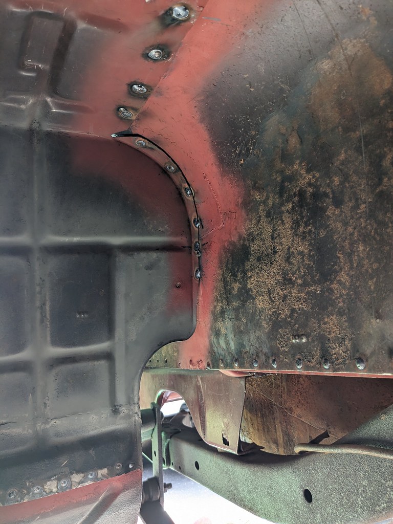
Now that these are done, the wheel houses are completely finished! I'm stoked to have gotten to this point. Just need a little paint and then move onto the spare tire well. This should be pretty straightforward, so it should move pretty quickly.
I started to move my attention to the fuel tank that I picked up from the junkyard. I got it really cheap and I'm going to use this for now. It had a few pinholes in it, but they have been repaired and hold water. I'm going to make a fuel pump recess panel and weld in a USCAR fuel pump ring to use some sort of in tank pump. The tank had a lot of varnish that took some time to get cleaned out, but is going to work just fine for me. Not the ideal tank, but given that I'll be deleting the spare tire well and ditching this tank when I run a Nerd Rods frame this will be a perfect temporary solution for me.

My biggest dilemma for this project is what fuel pump to run. The fuel tank, with the 2" recess will land right around 10.5" tall. My plan was to run a 5th gen Camaro SS tank, convert to fixed pressure and extend the height because the max is 7". But I'm not sure that is going to be my best solution. It's a long way to extend the height.

I got sick of looking at the bubbling roofline, and finally took a grinder to it. I was pleasantly surprised with most of the roof. There were a few pinholes, but there must have just been some contamination when the roof was painted as most of it wasn't rusty.
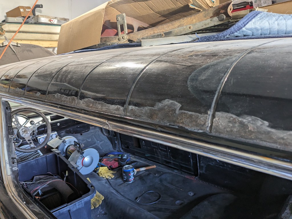
But then I found some bad at the rear corner... Thankfully the other side looks to be just some thing in the paint and I'll recoat it and try to paint match the best I can. I found out that a mid 70s to 92ish Chevy G vans have front fenders that at the top have the exact same curvature as the rear of the wagons. So I'll track one down and use it as a donor. Should be a pretty quick patch and then I can get the roof back in shape.

I'm going to be ordering some parts this week so I can get the rear seat mocked up as well as the engine and transmission. Will also try to work more on the spare tire well and possibly wrap up the rear cargo area.
Cheers,
Ryan

Once that was fully welded, I moved my attention to the passenger's side. I scuffed down and painted the inner structure to help prevent any future rust issues.

While I had the paint out, I also scuffed down and painted the rear floor pan section that I grafted in. Really glad to have this section done now.

I got busy, and didn't get any pictures, but I got the passenger side outer wheel houses mocked up and prepped for welding. Once I was happy with the fitment, I got everything fully welded.


Now that these are done, the wheel houses are completely finished! I'm stoked to have gotten to this point. Just need a little paint and then move onto the spare tire well. This should be pretty straightforward, so it should move pretty quickly.
I started to move my attention to the fuel tank that I picked up from the junkyard. I got it really cheap and I'm going to use this for now. It had a few pinholes in it, but they have been repaired and hold water. I'm going to make a fuel pump recess panel and weld in a USCAR fuel pump ring to use some sort of in tank pump. The tank had a lot of varnish that took some time to get cleaned out, but is going to work just fine for me. Not the ideal tank, but given that I'll be deleting the spare tire well and ditching this tank when I run a Nerd Rods frame this will be a perfect temporary solution for me.

My biggest dilemma for this project is what fuel pump to run. The fuel tank, with the 2" recess will land right around 10.5" tall. My plan was to run a 5th gen Camaro SS tank, convert to fixed pressure and extend the height because the max is 7". But I'm not sure that is going to be my best solution. It's a long way to extend the height.

I got sick of looking at the bubbling roofline, and finally took a grinder to it. I was pleasantly surprised with most of the roof. There were a few pinholes, but there must have just been some contamination when the roof was painted as most of it wasn't rusty.

But then I found some bad at the rear corner... Thankfully the other side looks to be just some thing in the paint and I'll recoat it and try to paint match the best I can. I found out that a mid 70s to 92ish Chevy G vans have front fenders that at the top have the exact same curvature as the rear of the wagons. So I'll track one down and use it as a donor. Should be a pretty quick patch and then I can get the roof back in shape.

I'm going to be ordering some parts this week so I can get the rear seat mocked up as well as the engine and transmission. Will also try to work more on the spare tire well and possibly wrap up the rear cargo area.
Cheers,
Ryan
The following 2 users liked this post by ryeguy2006a:
Motown 454 (08-21-2023), Zanie (07-19-2023)
#85
Thread Starter
Joined: Apr 2012
Posts: 2,032
Likes: 594
From: Ruckersville, VA
Progress slowed this week. I made a big push to get the wheel wells completely welded up and got a little burned out. I sprayed some rattle can paint on wheel wells to give them a finished look. I'm really happy with the end results. I'm going to spray some bedliner in there at some point, but wanted to look at the wheel wells in one color.


That's all the work I've done on the body. I've been continuing the parts search since hunting for parts is always something that I enjoy. I've been keeping an eye out for a seat in decent shape that wasn't ridiculously priced and was able to finally track one done. I was finding rusty seat frames and people were asking $800 bucks! I ended up driving a little farther than I wanted, but the seat is overall in great shape and not rusty at all. Bonus is it's complete with the tracks and side shells. There are some obvious tears in the seat bottoms, but they sorta match the vibe of the car so they will work as is for now. Looks like someone put the cover right over the original seat covers. Not sure if it's right or wrong, but they appear to have done a decent job.


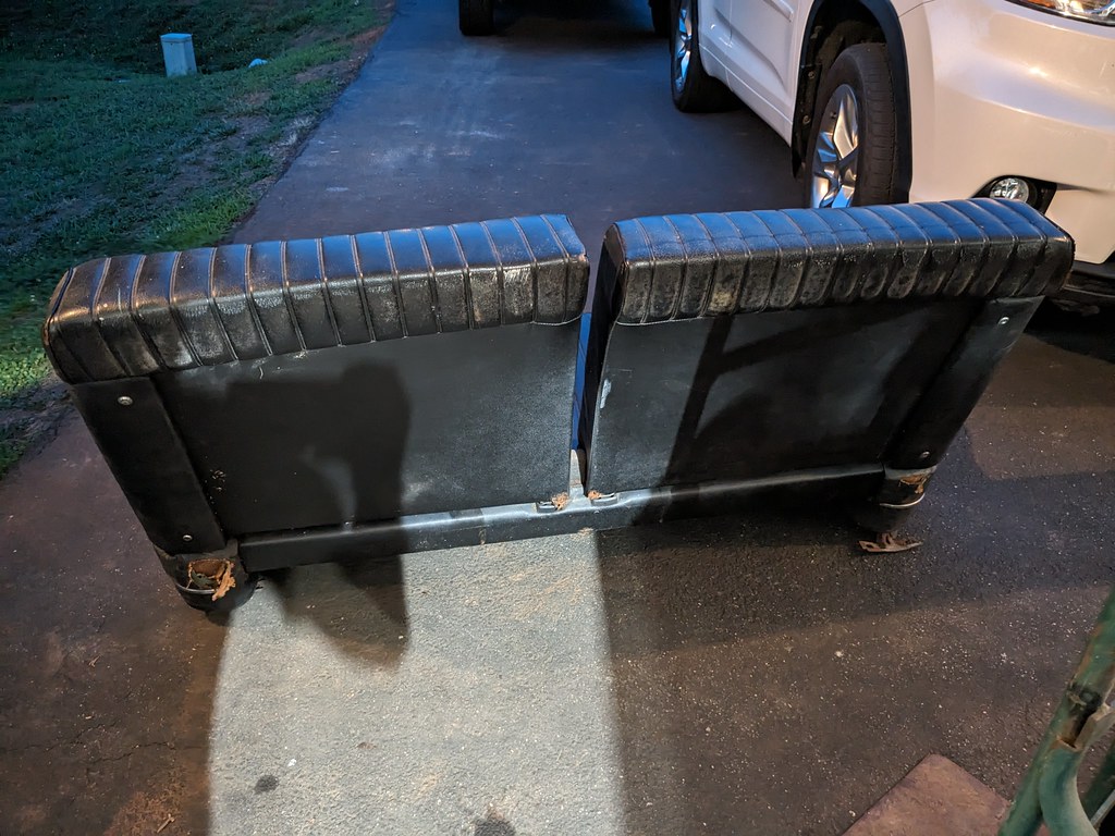
I couldn't wait to see what it felt like in the car so I installed it first thing when I got back. It fit like a glove in the car just like it should, and felt really good since I haven't really sat in the car since I bought it. I'm a taller guy, so I may need to eventually find some shorter seat tracks to lower the seat down some, but it feels great to finally have a seat.


Like I always do, I asked the guy that I bought the seat from if he had any other parts, and he happened to have a set of new shocks that he installed but never used. He sold them to me cheap, which is great since I don't plan to keep this frame long. He also had a 57 wagon fuel tank, which was in way better shape than the one I was planning to use, and he gave me a great bundle package on everything.
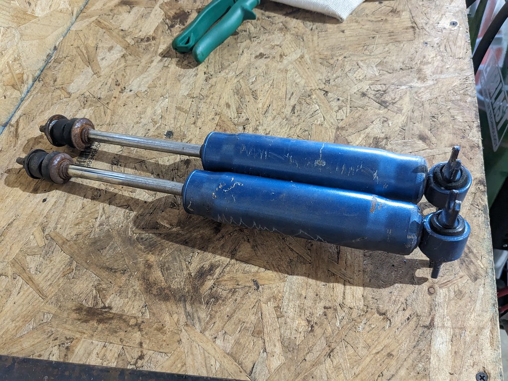
I also placed an order last week for some parts I need to get the motor mocked up, and the rear seat latches to get the rear seat mocked up. I also found a great deal on a new fuel pump that will fit the height of the wagon fuel tank. It's a new Delphi unit made for 09-13 Silverado's.


I couldn't wait to see what the rear seat looked like in the car so I quickly installed the rear seat latches and loosely installed the seats. I have the lower seat brackets just sitting on floor propping up the seat bottom for right now, but for just loosely mocking it up, everything fits great.


It's interesting how bolting a few seats in came make the car feel so much more complete. I'm getting so excited to get this car back on the road. I've got a line on a pair of G20 Chevy Van fenders to make the repairs on the rear roof, and the 55-57 engine mounts from CPP should be delivered today. I can't wait to get the engine mocked up and see what, if any, modifications I'll need to make to get it all to fit properly.
Cheers,
Ryan


That's all the work I've done on the body. I've been continuing the parts search since hunting for parts is always something that I enjoy. I've been keeping an eye out for a seat in decent shape that wasn't ridiculously priced and was able to finally track one done. I was finding rusty seat frames and people were asking $800 bucks! I ended up driving a little farther than I wanted, but the seat is overall in great shape and not rusty at all. Bonus is it's complete with the tracks and side shells. There are some obvious tears in the seat bottoms, but they sorta match the vibe of the car so they will work as is for now. Looks like someone put the cover right over the original seat covers. Not sure if it's right or wrong, but they appear to have done a decent job.


I couldn't wait to see what it felt like in the car so I installed it first thing when I got back. It fit like a glove in the car just like it should, and felt really good since I haven't really sat in the car since I bought it. I'm a taller guy, so I may need to eventually find some shorter seat tracks to lower the seat down some, but it feels great to finally have a seat.


Like I always do, I asked the guy that I bought the seat from if he had any other parts, and he happened to have a set of new shocks that he installed but never used. He sold them to me cheap, which is great since I don't plan to keep this frame long. He also had a 57 wagon fuel tank, which was in way better shape than the one I was planning to use, and he gave me a great bundle package on everything.

I also placed an order last week for some parts I need to get the motor mocked up, and the rear seat latches to get the rear seat mocked up. I also found a great deal on a new fuel pump that will fit the height of the wagon fuel tank. It's a new Delphi unit made for 09-13 Silverado's.


I couldn't wait to see what the rear seat looked like in the car so I quickly installed the rear seat latches and loosely installed the seats. I have the lower seat brackets just sitting on floor propping up the seat bottom for right now, but for just loosely mocking it up, everything fits great.


It's interesting how bolting a few seats in came make the car feel so much more complete. I'm getting so excited to get this car back on the road. I've got a line on a pair of G20 Chevy Van fenders to make the repairs on the rear roof, and the 55-57 engine mounts from CPP should be delivered today. I can't wait to get the engine mocked up and see what, if any, modifications I'll need to make to get it all to fit properly.
Cheers,
Ryan
The following 4 users liked this post by ryeguy2006a:
#86
Joined: Aug 2007
Posts: 2,412
Likes: 110
From: Where the Navy tells me to go
#87
Thread Starter
Joined: Apr 2012
Posts: 2,032
Likes: 594
From: Ruckersville, VA
I reached out to Carl at Vaporworx and he suggested this pump, and he also gave me a link to his site that shows the heights for common fuel pumps.
https://www.vaporworx.com/wp-content/uploads/2016/01/Fuel-Module-Dims.pdf
That's a great question on the Van fenders haha. I found a post on FB where a guy named Randy Ranker who restores lots of Nomad's mentioned they have the right curves to make a good patch. I wished I could take credit for the discovery haha.
The following users liked this post:
AAIIIC (08-02-2023)
#88
Thread Starter
Joined: Apr 2012
Posts: 2,032
Likes: 594
From: Ruckersville, VA
I received my CPP engine mounts in the middle of last week and was dying to get the engine together for a test fit. The kit I bought came with the typical side mount SBC rubber engine mounts and I bought the set of SBC LS adapter plates to bolt it all together. Unfortunately, Holley doesn't make a kit like they did for my 1968 Camaro, so after a bunch of research, this setup seemed like the most common setup to work with the existing headers and pans.
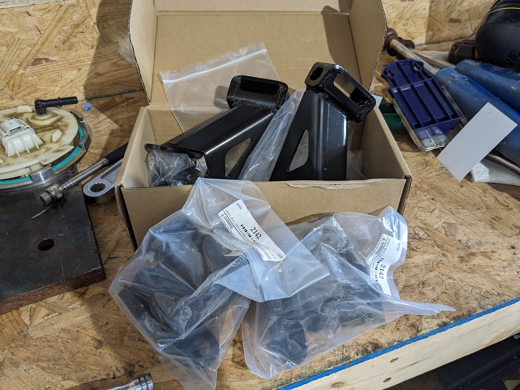
Step one for these engine mounts is to drill out two rivets on each side of the frame in order to bolt on these conversion mounts. Back in 55-57, they used a front mounted engine mount with no side mounted provisions. These mounts were adapted a long time ago when people wanted to swap newer SBC/BBC's into the cars for more performance.
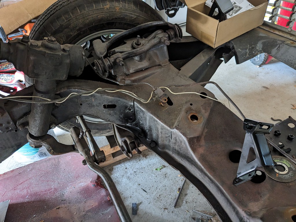
I had to enlarge the holes slightly to 3/8" to be able to bolt up the mounts. I wanted to test fit the engine first, before I drilled the top holes. Once the final engine placement is confirmed to be good, I'll drill 2 holes from the top and bolt them down final. I may put a few welds on them as well for good measure.
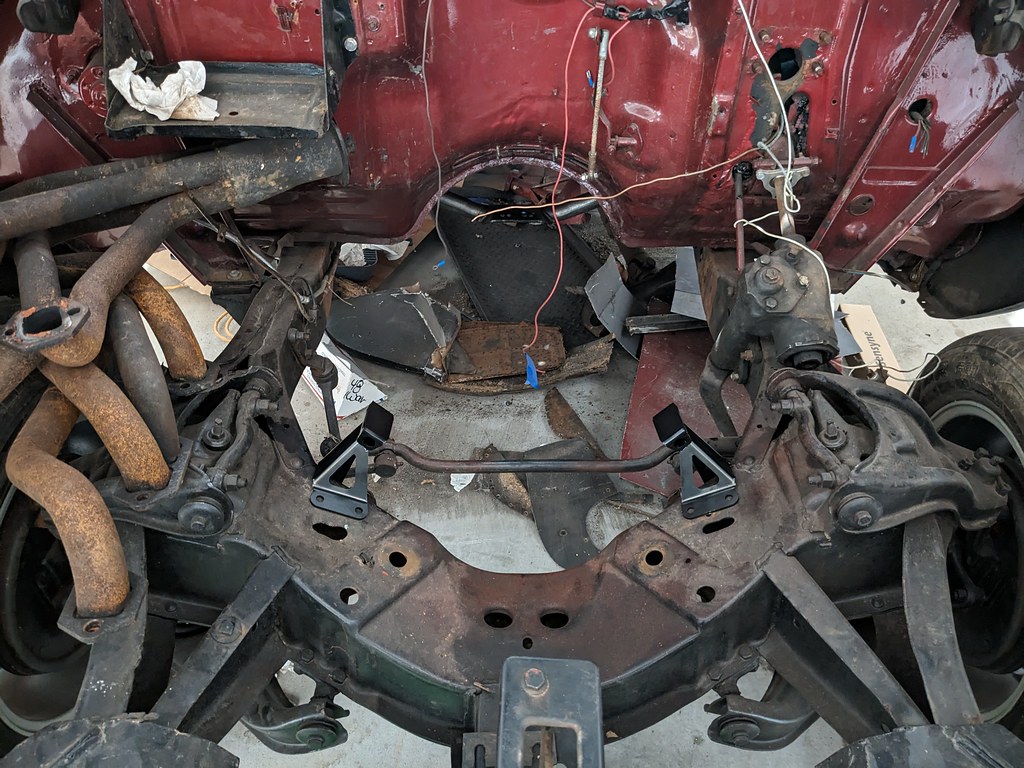
First step in the mock up phase was putting the pan I'm planning to run on the engine. I bolted it down with 4 bolts since it's just mock up. I got this pan for free from someone who was trying to get tie rod clearance on his application. I'll weld in some plates if this fits my application. If not, I'll keep it for another project.
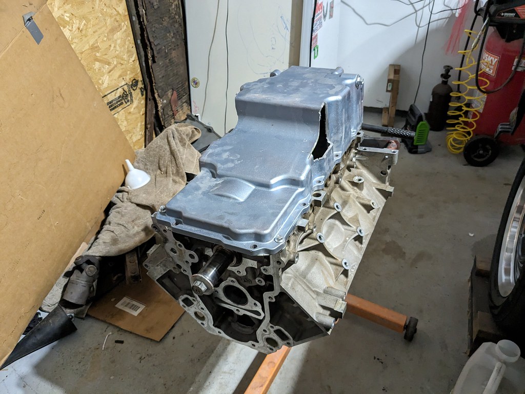
Flipped it around and got the engine off of the stand. Ready to get it bolted to the 4L80e. No flexplate because again, just mock up.
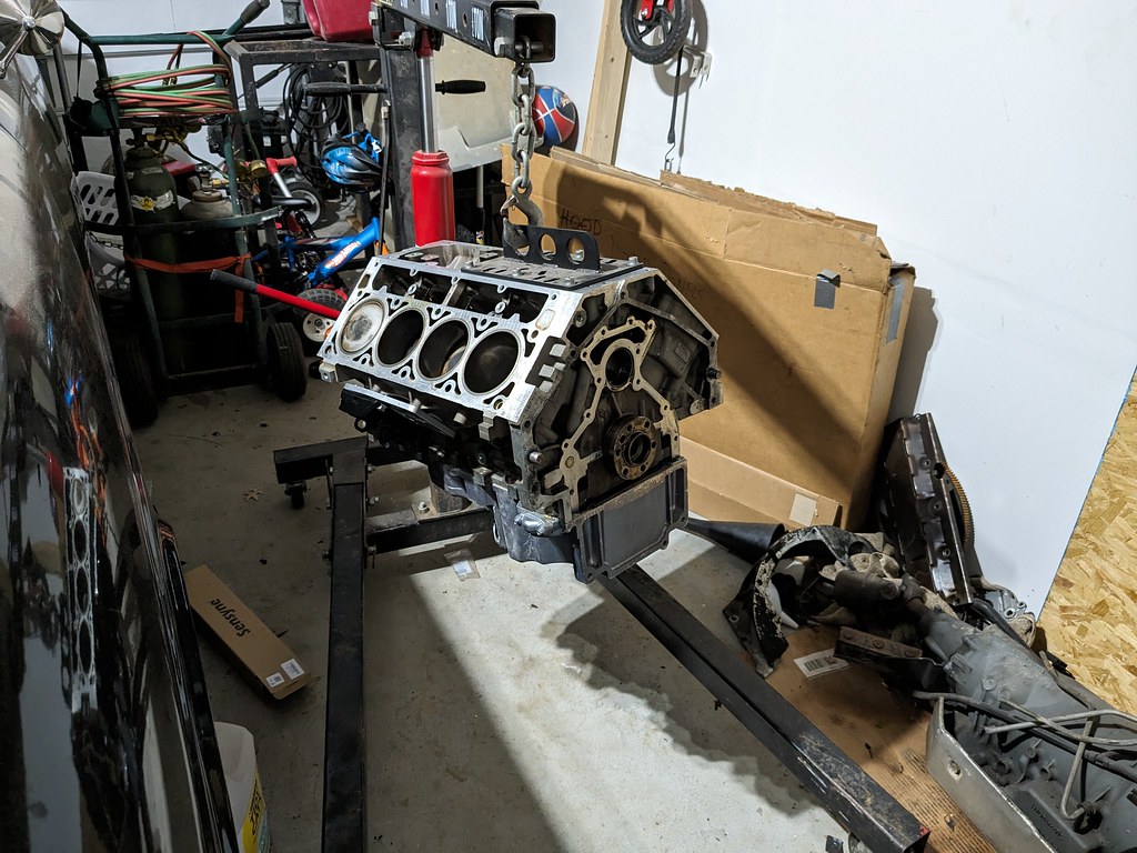
Mated up the engine and trans and it went great. Just had to track down some bolts. I'll get all new bolts when I am ready for final installation.
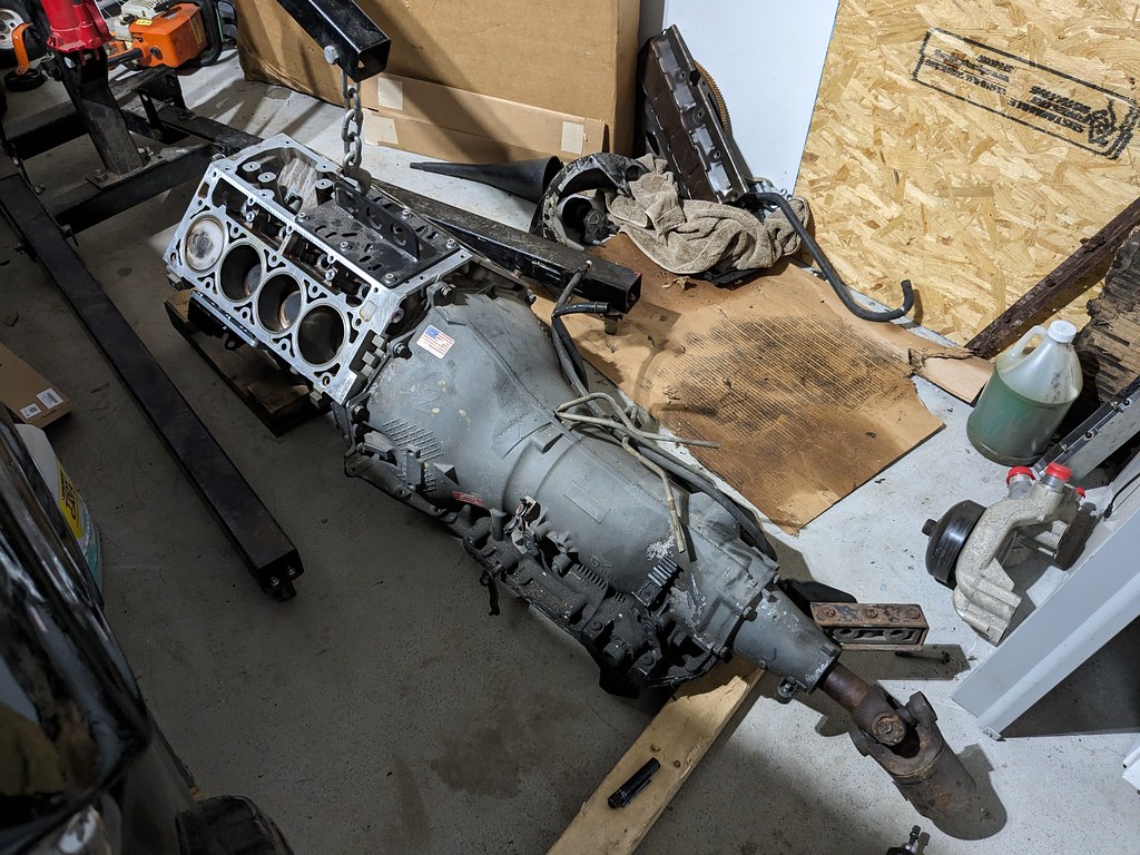
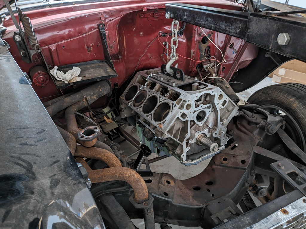
Wow, that trans is heavy! It was quite the task to lift the trans high enough to get over the grill. I had to lift it manually and spin it over the grill. I couldn't lift it any higher because the boom was hitting the hood. I also had to move the trans crossmember back about 10" from the Turbo350 position it was in. It's an aftermarket crossmember so that was a big plus. Here it was with the trans crossmember roughly on the mount, and the engine roughly in place. Unfortunately, there's an issue with the oil pan fitment...
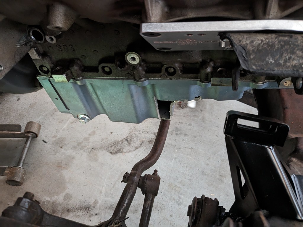
I thought that it would be close with the fitment of that pan, but looks like I won't have enough adjustability to move it to any closer to the firewall. So, looks like I'll be needing a new pan.
So with that information, I decided to pull the oil pan and continue with the mockup. Once the pan was out of the way, I was able to get the engine down into the engine stands and set to 3.8* down. Lots of clearance with the trans, and should bolt up to the trans crossmember. For now I'm propping it up with a jack stand.
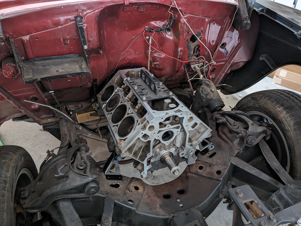
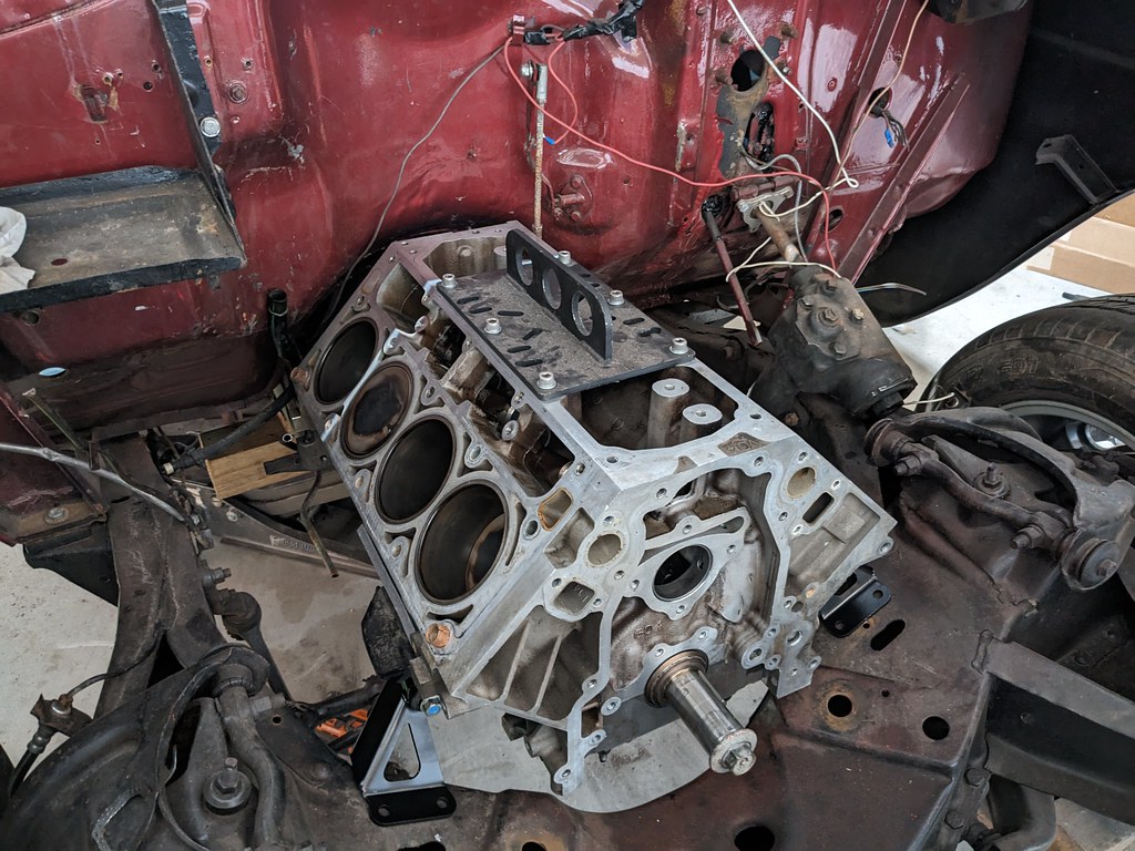
Now that the engine is in essentially the final spot, I'm going to start bolting on the heads, intake and manifolds to see how it's all going to fit. Pretty excited for that.
Cheers,
Ryan

Step one for these engine mounts is to drill out two rivets on each side of the frame in order to bolt on these conversion mounts. Back in 55-57, they used a front mounted engine mount with no side mounted provisions. These mounts were adapted a long time ago when people wanted to swap newer SBC/BBC's into the cars for more performance.

I had to enlarge the holes slightly to 3/8" to be able to bolt up the mounts. I wanted to test fit the engine first, before I drilled the top holes. Once the final engine placement is confirmed to be good, I'll drill 2 holes from the top and bolt them down final. I may put a few welds on them as well for good measure.

First step in the mock up phase was putting the pan I'm planning to run on the engine. I bolted it down with 4 bolts since it's just mock up. I got this pan for free from someone who was trying to get tie rod clearance on his application. I'll weld in some plates if this fits my application. If not, I'll keep it for another project.

Flipped it around and got the engine off of the stand. Ready to get it bolted to the 4L80e. No flexplate because again, just mock up.

Mated up the engine and trans and it went great. Just had to track down some bolts. I'll get all new bolts when I am ready for final installation.

Wow, that trans is heavy! It was quite the task to lift the trans high enough to get over the grill. I had to lift it manually and spin it over the grill. I couldn't lift it any higher because the boom was hitting the hood. I also had to move the trans crossmember back about 10" from the Turbo350 position it was in. It's an aftermarket crossmember so that was a big plus. Here it was with the trans crossmember roughly on the mount, and the engine roughly in place. Unfortunately, there's an issue with the oil pan fitment...

I thought that it would be close with the fitment of that pan, but looks like I won't have enough adjustability to move it to any closer to the firewall. So, looks like I'll be needing a new pan.

So with that information, I decided to pull the oil pan and continue with the mockup. Once the pan was out of the way, I was able to get the engine down into the engine stands and set to 3.8* down. Lots of clearance with the trans, and should bolt up to the trans crossmember. For now I'm propping it up with a jack stand.


Now that the engine is in essentially the final spot, I'm going to start bolting on the heads, intake and manifolds to see how it's all going to fit. Pretty excited for that.
Cheers,
Ryan
The following 3 users liked this post by Jimbo1367:
#90
Thread Starter
Joined: Apr 2012
Posts: 2,032
Likes: 594
From: Ruckersville, VA
Thank Jimbo! I really want to get this car running and driving by the end of September.
Now that the engine is in place, I'm so excited to start bolting parts on for mock up. Went from a bare short block to a full engine pretty quickly. Everything will get a good cleaning before final install, but for now I can check fitments.
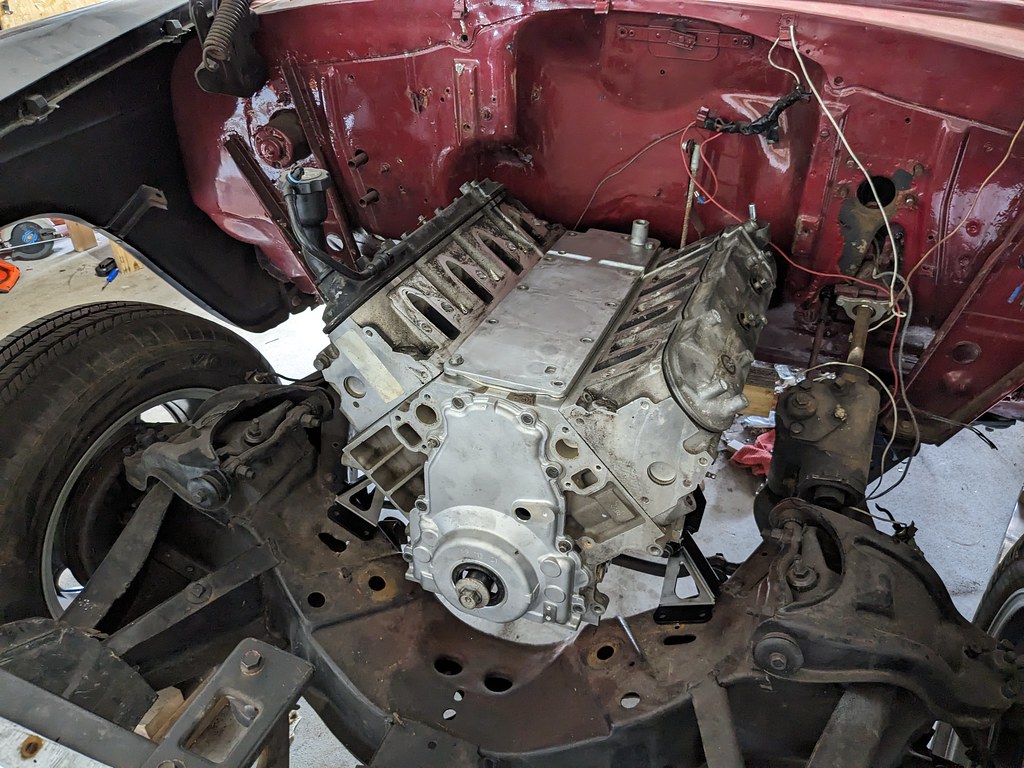
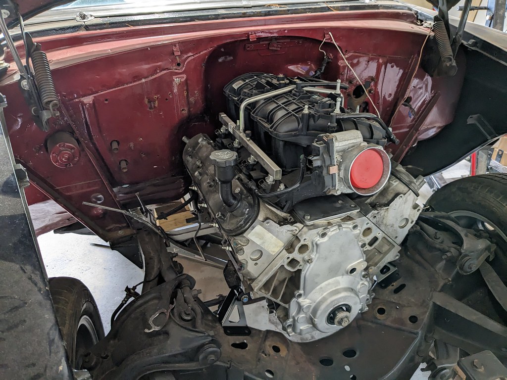

I really wanted to get the cylinder heads and intake on to check the height of the intake since it's a tall truck intake. Shut the hood and there's miles of clearance. Next big question mark was the exhaust manifolds that I had. I bought a TBSS intake from a junk yard over 6 years ago for my Camaro, but ended up with a pair of shorty headers. Glad I hung onto this because it's a perfect fit! Not sure if the heat shield will fit too, but without it there's tons of clearance. Huge win!


Passenger side wasn't really a concern as most of the time with LS swaps there's a bunch of clearance here. This was no exception and I think the stock truck flanges will bolt up and work perfectly as well.

Then one other thing that was a question mark was the stock electric wiper motor. I was stoked that it fit without any issues and will have tons of clearance as well. The bump in the intake allows it to perfectly clear. I'm very happy that everything is fitting together so nicely.

Lots of pictures for not a whole lot of work, but thought it was worth an update. I'm starting to get distracted by the mechanical work as that is more fun to me than the metal work. I need to finish up the rear seat install and weld the seat brackets to the floor. Right now they are just sitting in place, but I need to center them and spot weld in their final places.
Cheers,
Ryan
Now that the engine is in place, I'm so excited to start bolting parts on for mock up. Went from a bare short block to a full engine pretty quickly. Everything will get a good cleaning before final install, but for now I can check fitments.


I really wanted to get the cylinder heads and intake on to check the height of the intake since it's a tall truck intake. Shut the hood and there's miles of clearance. Next big question mark was the exhaust manifolds that I had. I bought a TBSS intake from a junk yard over 6 years ago for my Camaro, but ended up with a pair of shorty headers. Glad I hung onto this because it's a perfect fit! Not sure if the heat shield will fit too, but without it there's tons of clearance. Huge win!


Passenger side wasn't really a concern as most of the time with LS swaps there's a bunch of clearance here. This was no exception and I think the stock truck flanges will bolt up and work perfectly as well.

Then one other thing that was a question mark was the stock electric wiper motor. I was stoked that it fit without any issues and will have tons of clearance as well. The bump in the intake allows it to perfectly clear. I'm very happy that everything is fitting together so nicely.

Lots of pictures for not a whole lot of work, but thought it was worth an update. I'm starting to get distracted by the mechanical work as that is more fun to me than the metal work. I need to finish up the rear seat install and weld the seat brackets to the floor. Right now they are just sitting in place, but I need to center them and spot weld in their final places.
Cheers,
Ryan
#91
Thread Starter
Joined: Apr 2012
Posts: 2,032
Likes: 594
From: Ruckersville, VA
Thanks! I'm having a lot of fun building this car.
Moving forward, I was able to get the transmission crossmember mocked up and it's going to work great with the right driveline angles. It does still need to be tilted up about a 1/2" more, but there is a lip in the tunnel that needs a little BFH work.
I placed an order from Summit and got the rest of the bolts, gaskets and a new piston ring compressor to get the short block finished up. I'm going to be gapping the rings for boost because down the road I'll be adding a turbo, or possibly an LSA supercharger. I've got a buddy doing an LSA swap right now and it's making me want to put on on this car too...
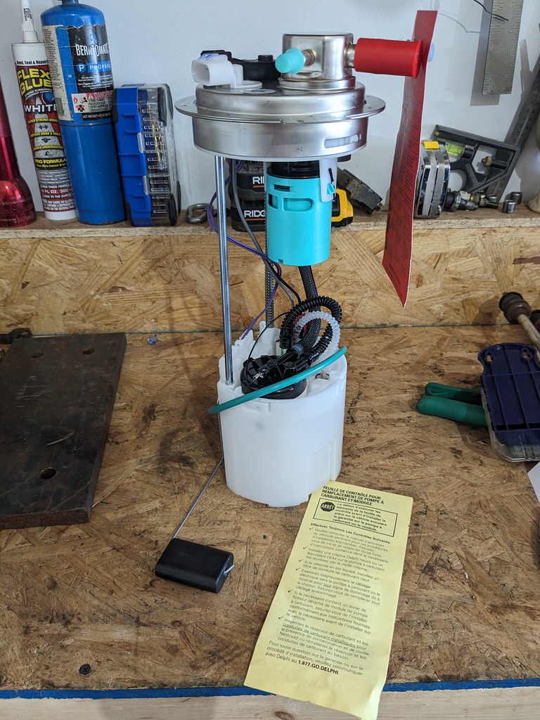
Since the engine is still mocked in the car, I was side tracked with my fuel system. My plan from the beginning was to use a stock fuel pump to have the most reliability, and my experience with the 10-15 Camaro SS fuel pump was fantastic. Vaporworx sells a conversion kit to allow them to run at a fixed 58 or 43 psi with a kit. So that was my plan, but after I decided to use the wagon fuel tank that pump is way too short. The CTSV and SS Camaro fuel pump assemblies only go to about 7.25" tall and my tank with a recess panel for the pump needs to be about 11" tall. After some thought, I decided that I'd buy an SS pump and build my own pump using other parts I have acquired. I've nicknamed this the "Frankenstein Pump" since it will be made using so many different parts. CTS-V fuel hat, Silverado rods/springs, SS Camaro fuel pump lower section and 4th gen Camaro fuel pressure regulator.
Now, before someone chimes in and says I should have just bought the PWM kit to control the fuel pump that did cross my mind. However, I've still got so many other parts to buy and that money could be used for other things right now and I already had the fixed pressure adapter. Plus I like a good challenge and if it keeps me on track with my budget, it's a win-win.
I did this several weeks ago, but I started off with the first wagon tank that I picked up for really cheap and used that as my test tank. I cut a hole in it where I new I wanted the fuel pump and made sure that this whole project would even be possible. It's a very tight spot where the fuel pump fits flush on the bottom of the tank, but it fits and that's what's most important. Time to collect parts.
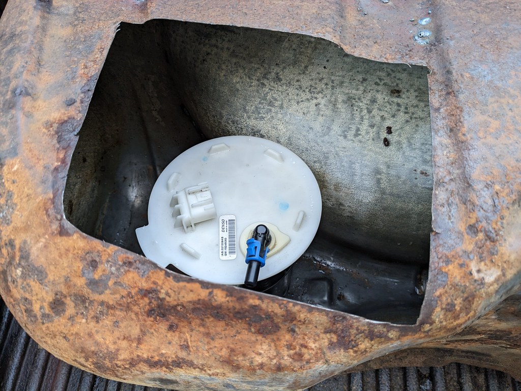
While I was figuring out what rods to use for when I extended the SS fuel pump, I came across a new Delphi pump out of a 09-13 Silverado for crazy cheap on eBay. It also came with a new green seal, so I picked that up for $35 bucks.
Also on eBay I found a wrecking yard selling a 13 SS fuel pump with 40k miles and they accepted my offer for $45 bucks. I now had all the parts for my "Frankenstein Pump".
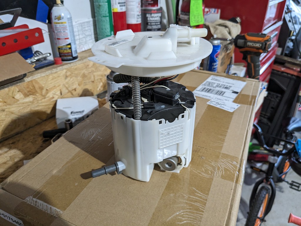
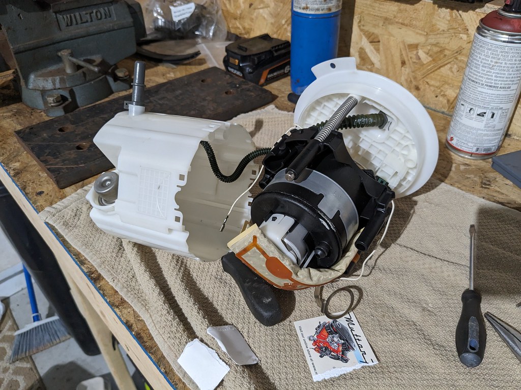
First step was to disassemble the two pumps. First up was the SS fuel pump. There is an inner assembly that is held in with some clips that had to be popped out to remove the clips for the top lid to come off.
After I robbed the rods from the Silverado pump, I did a quick test fit using the SS Camaro top fuel lid and it gave me the height that I needed at full compression. I bought a new 10mm corrugated hose a while ago because I was pretty sure I was going to be doing this project at some point. It fits perfectly for this application.
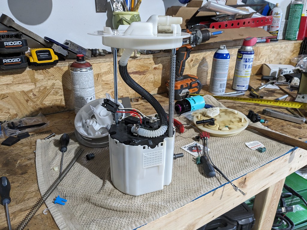
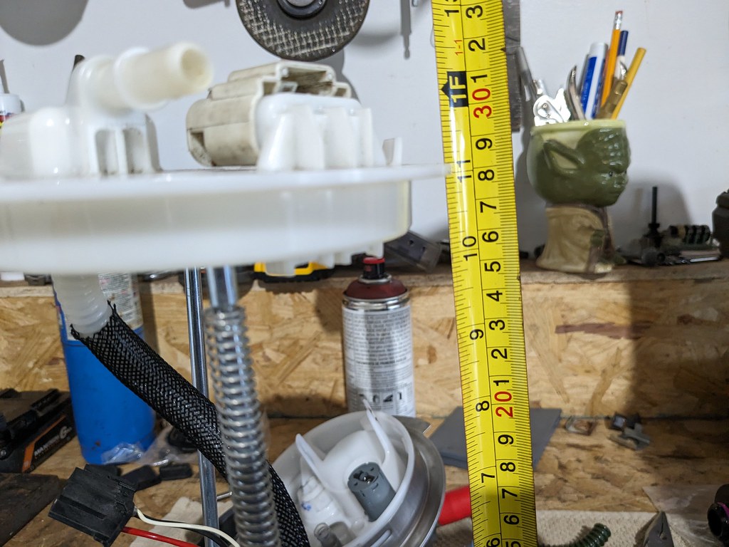
While I liked the SS fuel hat better, where the rods are held in was a press fit and too loose to fit the longer rods. I had a spare CTSV fuel hat from my Camaro and that was a perfect fit. And there were slots in the SS pump lower section for the rods to go since the rod spacing is different between the SS and CTSV.
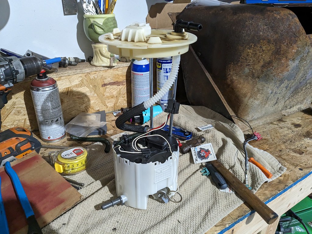
Now that it's all fitting together nicely, it's time to work on the fitment into the fuel tank. Glad that I had a spare tank to play with since I cut this one too far on the vertical side. Perfect for getting me measurements though.

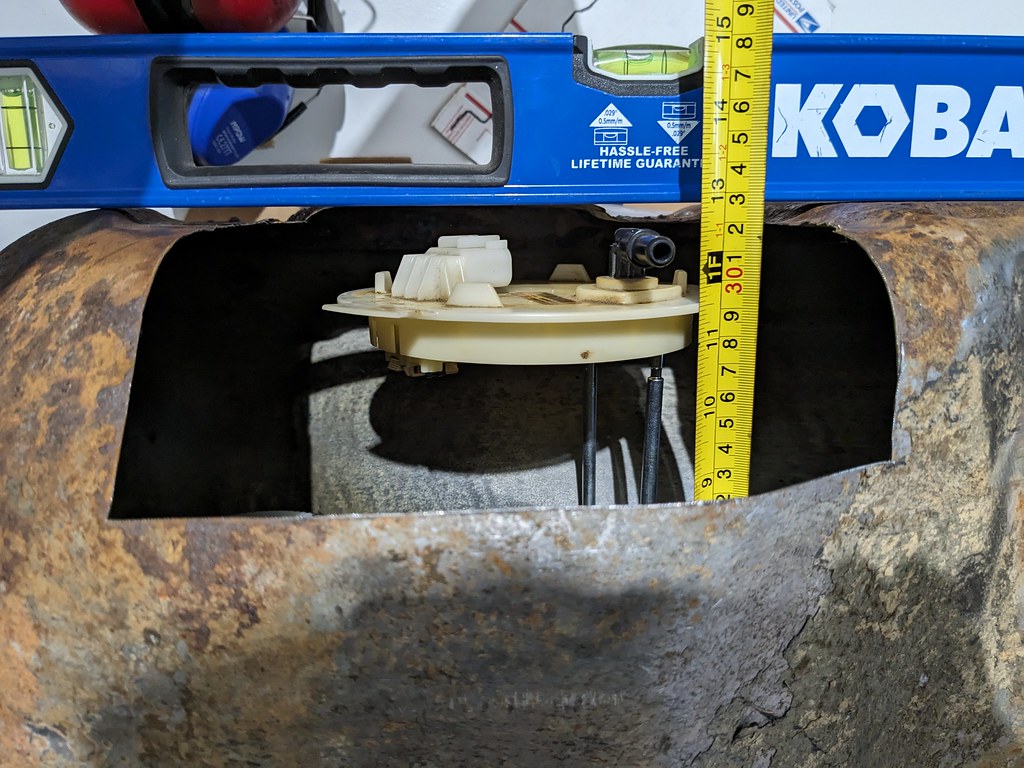
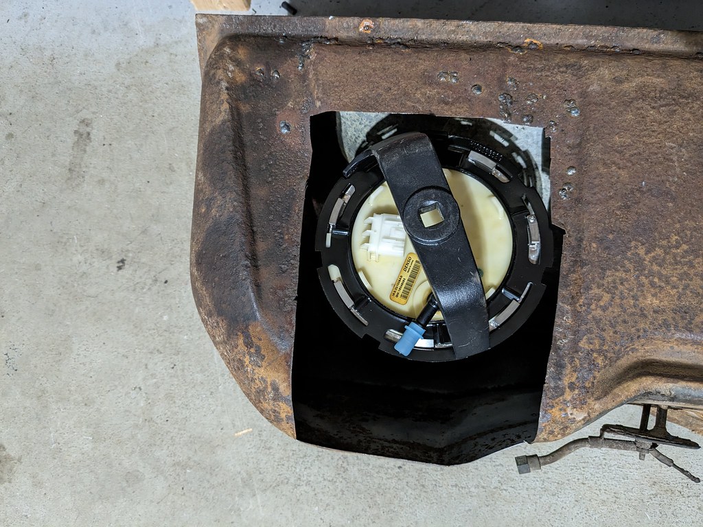
I also wanted to make sure that there would be enough room for me to get a tool around the fuel pump ring.
At this point, I'm completely satisfied with the fitment of this pump in the tank so I took some measurements off the test tank and transferred them to my good tank. I made sure that my cuts were way smaller than needed to be so that I could creep up on the final cut lines.
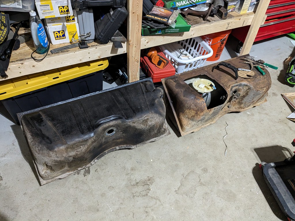
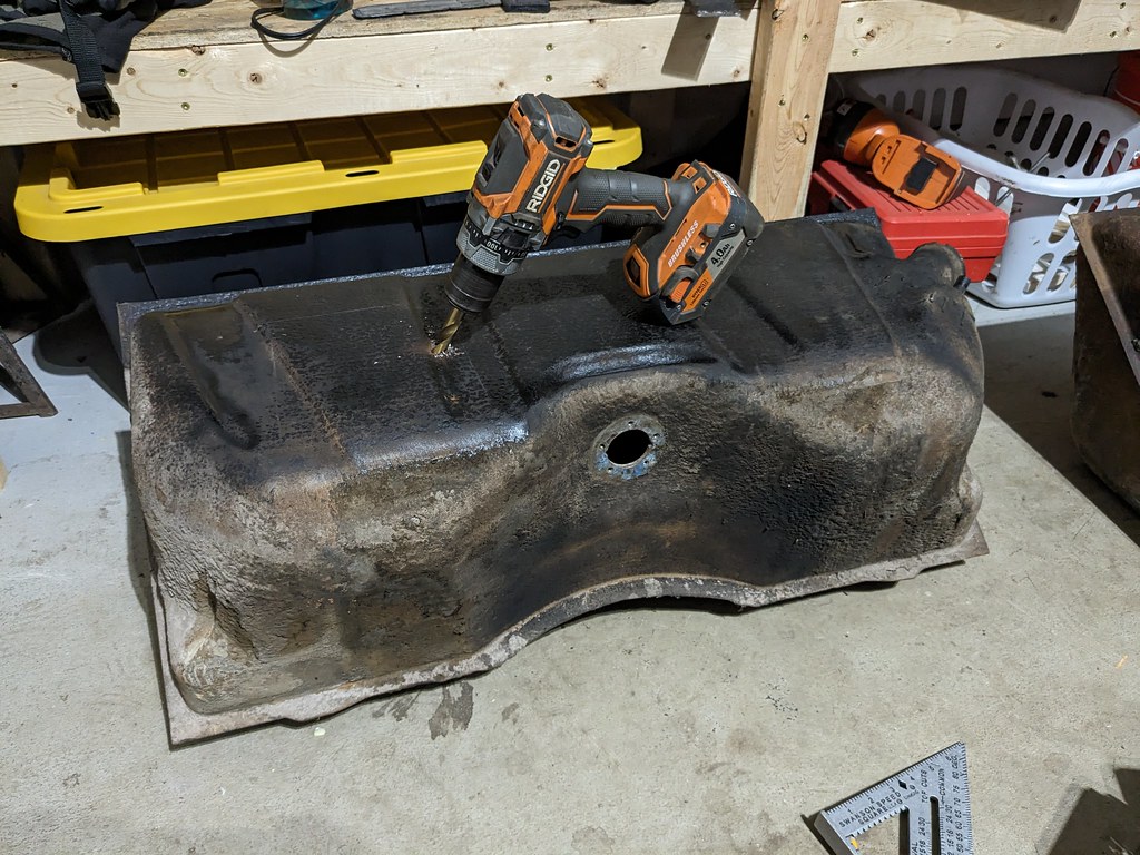
I wanted to play around with some cardboard to see what the recess panel will look like and fit. Now because there was such a tight fit for where the fuel pump had to be placed, I wanted to make sure that the recess panel was centered as perfectly as I could get it. I build the recess panel template and used the inner inner diameter of the locking ring for my initial hole. With the template fitting snuggly on the top of the fuel pump hat I placed the pump in the exact spot it needed to be in the fuel tank. That centered up the template and allowed me to make some marks for my final cuts.
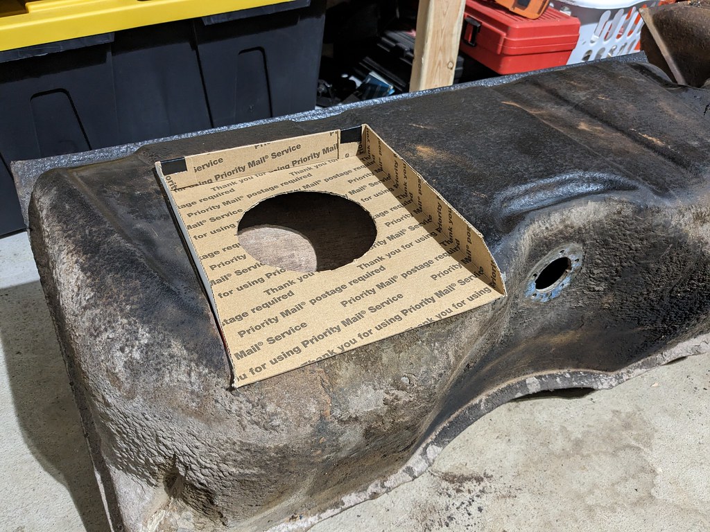
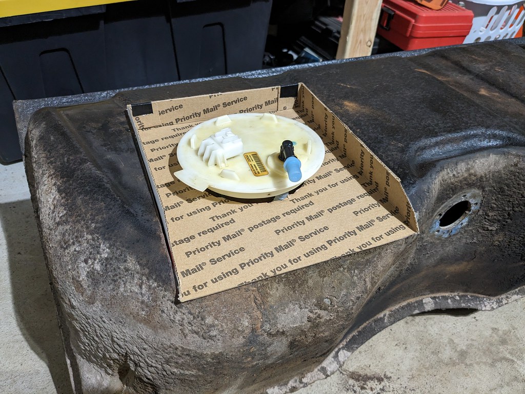
Now that I confirmed the fuel pump is exactly where I wanted it, I cut the hole larger to test fit the actual fuel pump ring I'll be using and once again checked the fitment.
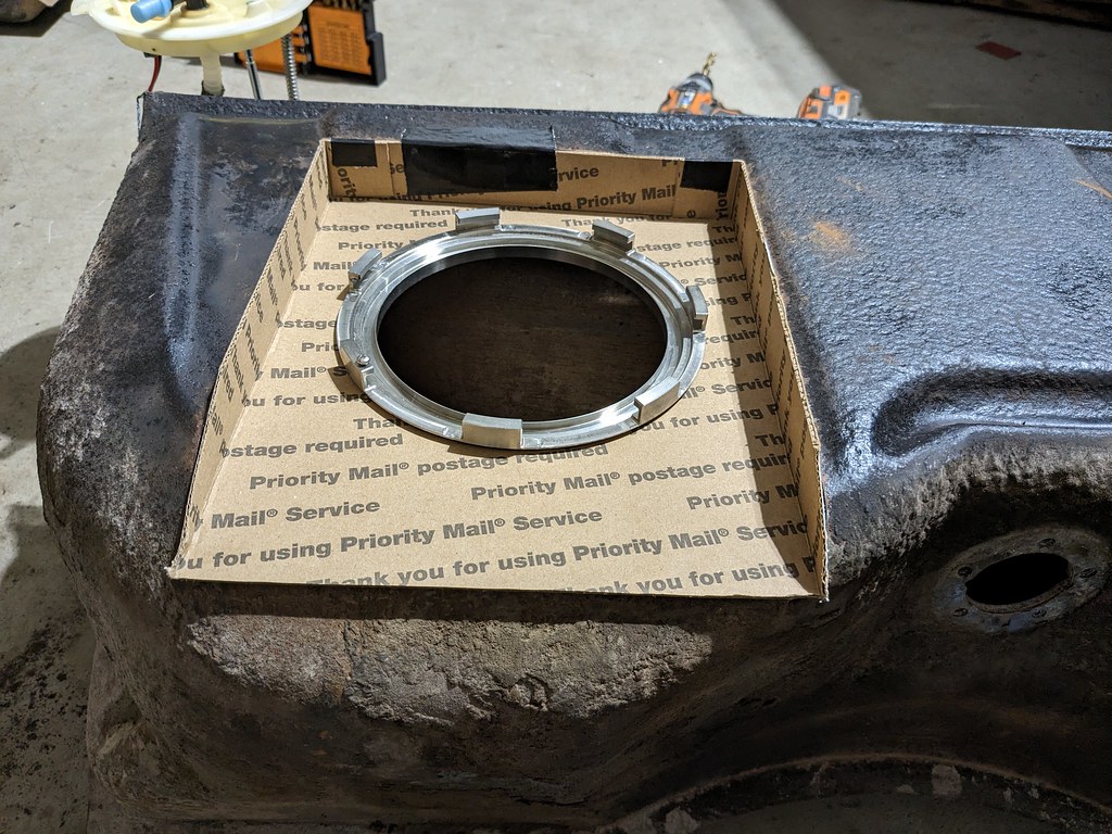
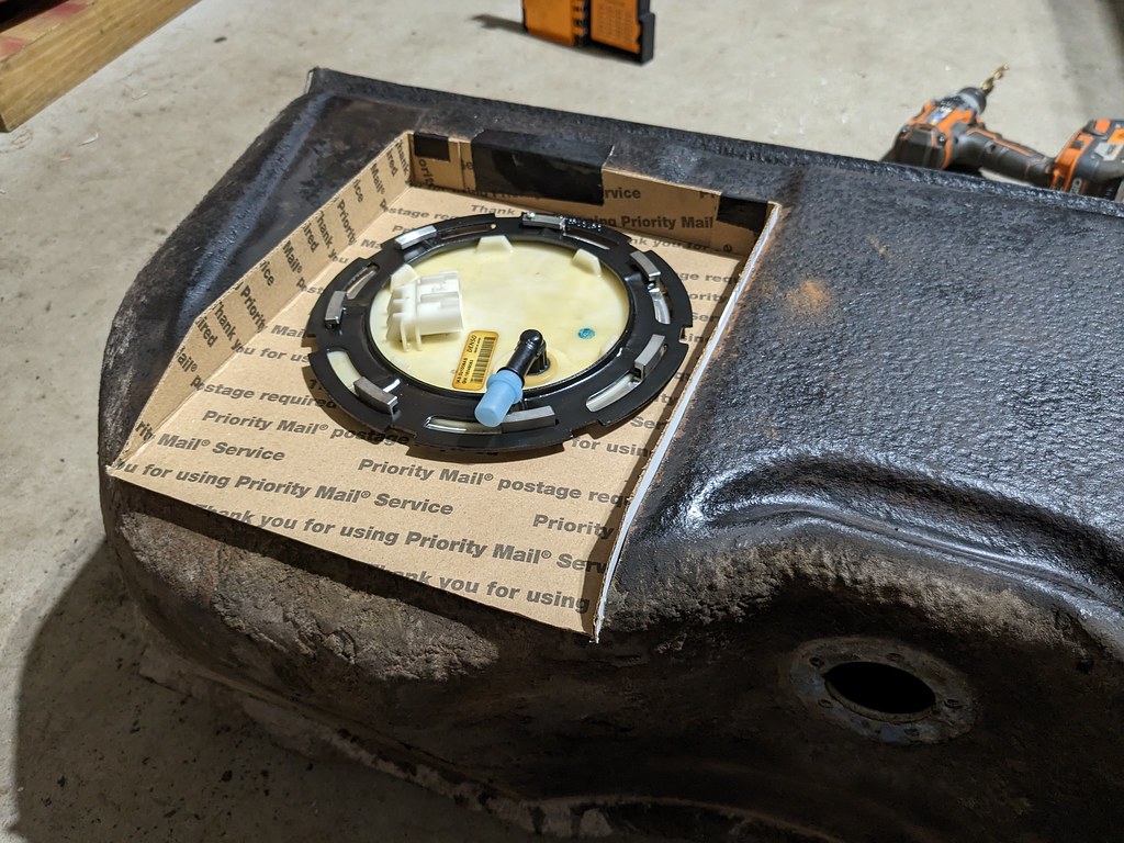
I'm very pleased with the fitment and there should be plenty of clearance above the fuel pump. With it all in place, it was now time for the first test fit in the car.
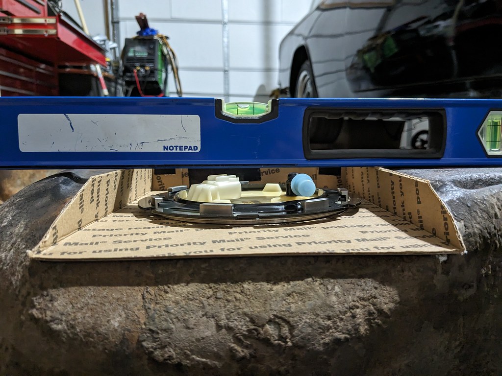
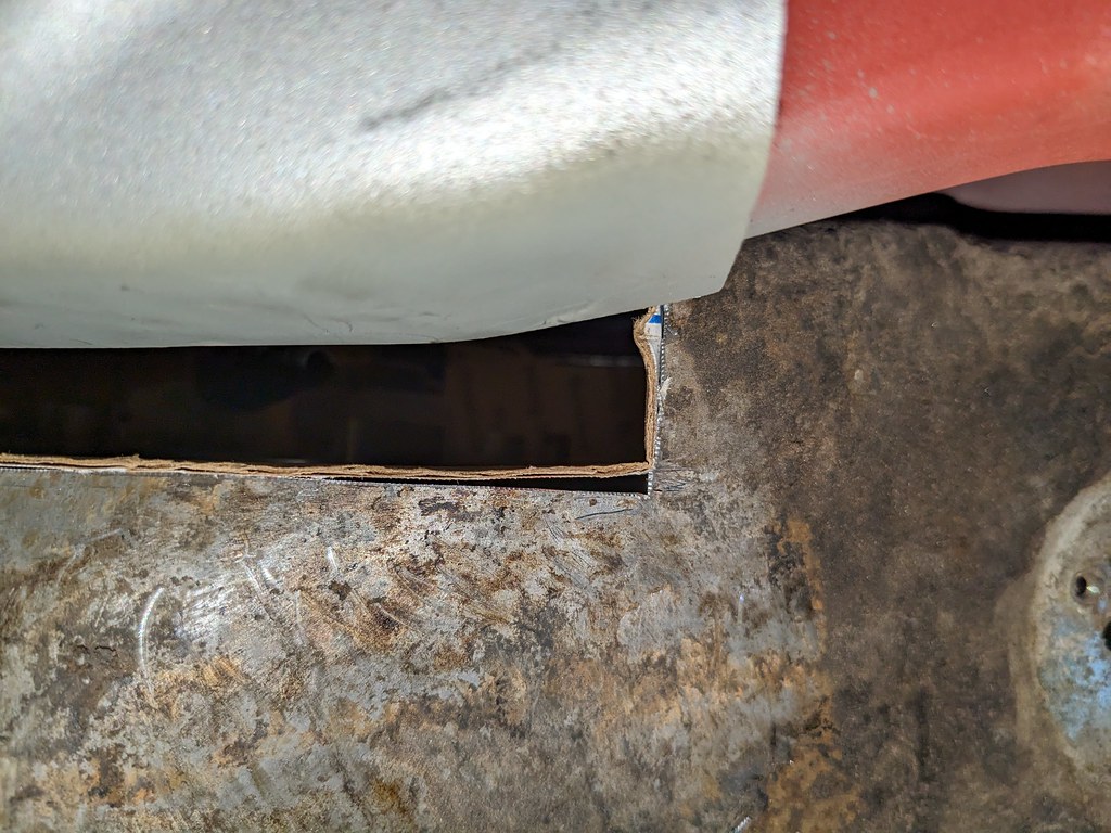
Huge fail!! But this is why I've come to realize that test fitting parts before a final weld or assembly is so important. While there is plenty of space above the fuel pump, there isn't anywhere for the fuel line to go.
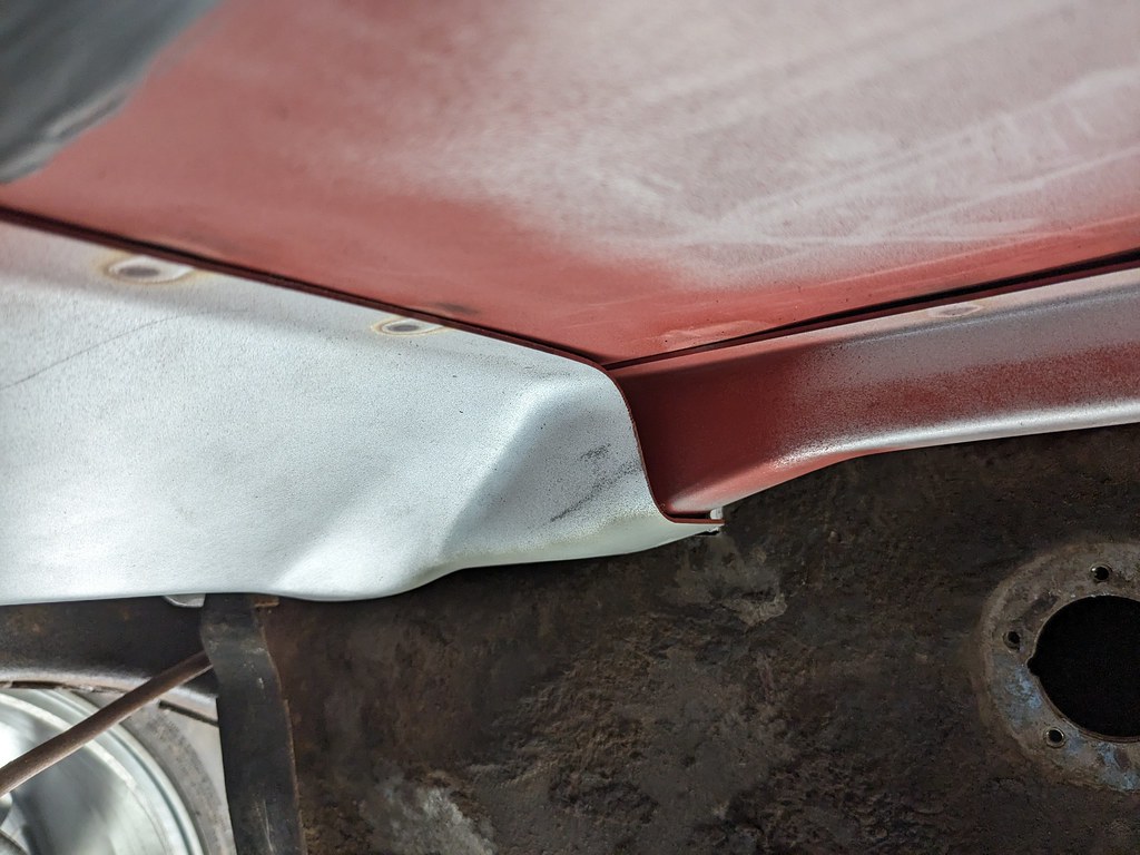
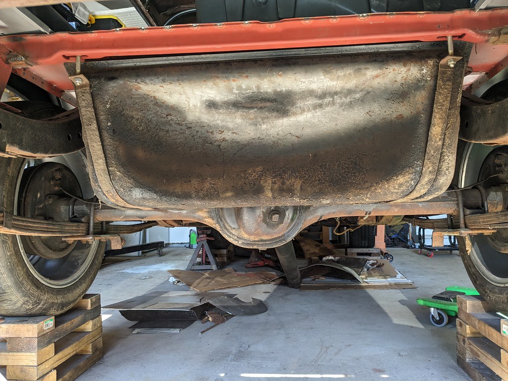
I marked where it needed to be for a fuel line to be, then pulled it out and started over. I had to make a new template because the old one wasn't long enough on the sides. trimmed the tank about 3/4" lower then reinstalled for a second test fit. It's perfect now and I'm very pleased.
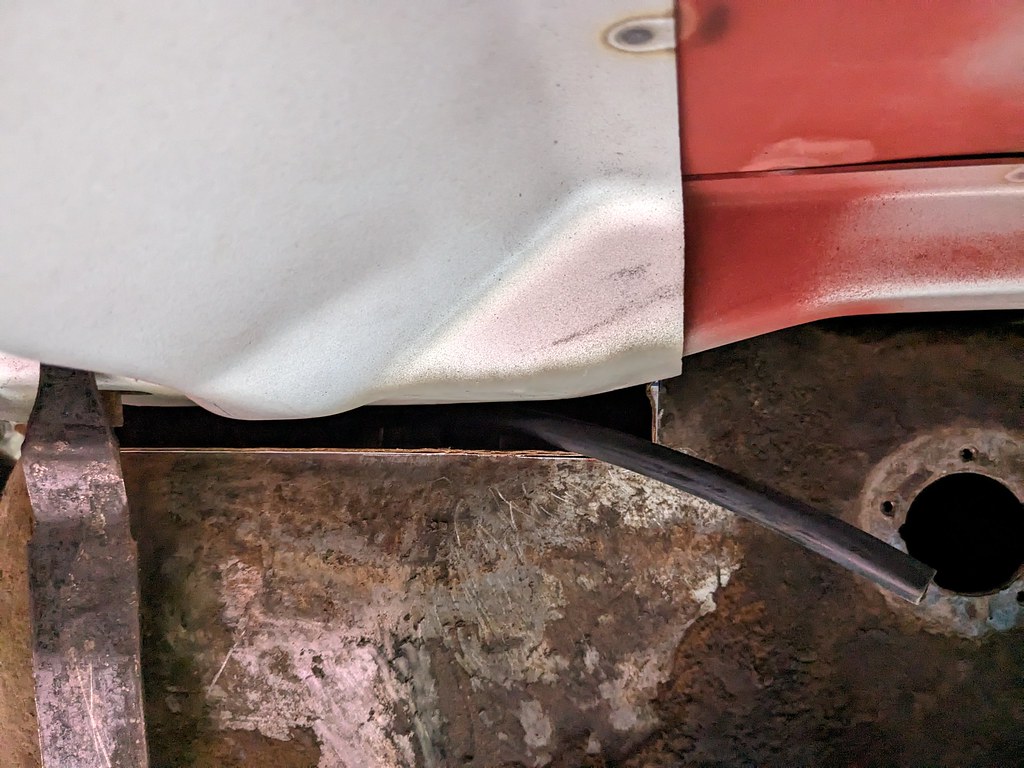
Miles of room above the fuel hat.
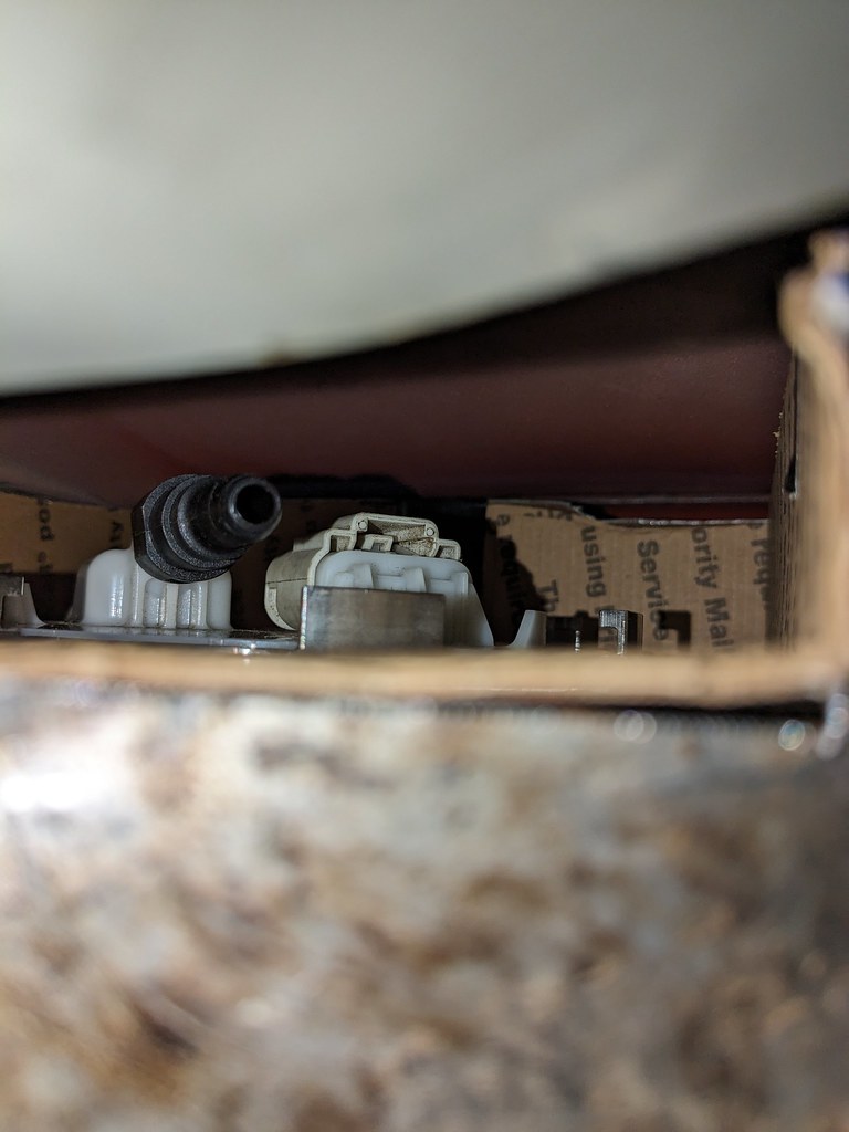
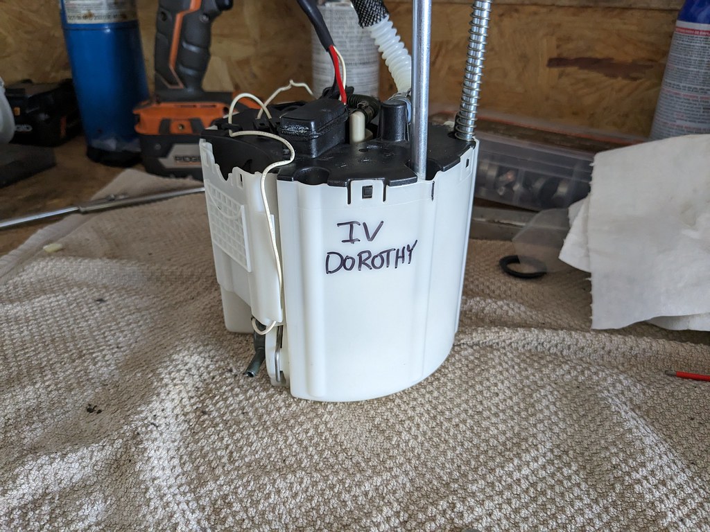
Here's the final mock up. One minor adjustment I'll need to do is shorten the rods just slightly because they are just a touch too long now that I had to lower the recess panel. That will be a very quick process, but here's the completed fuel pump. Next up will be transferring my template to metal and getting it welded in place.
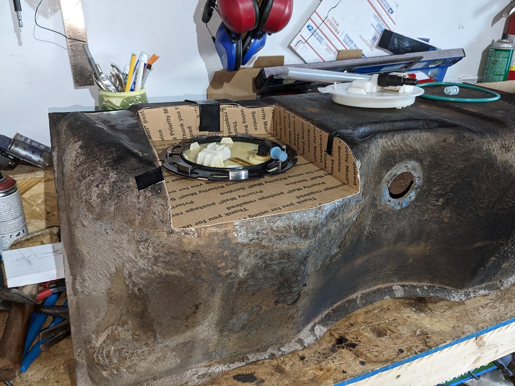
My buddy Jonathan said that my fuel pump looks a lot like the tornado machine from Twister. So I added a mark for Dorothy IV haha
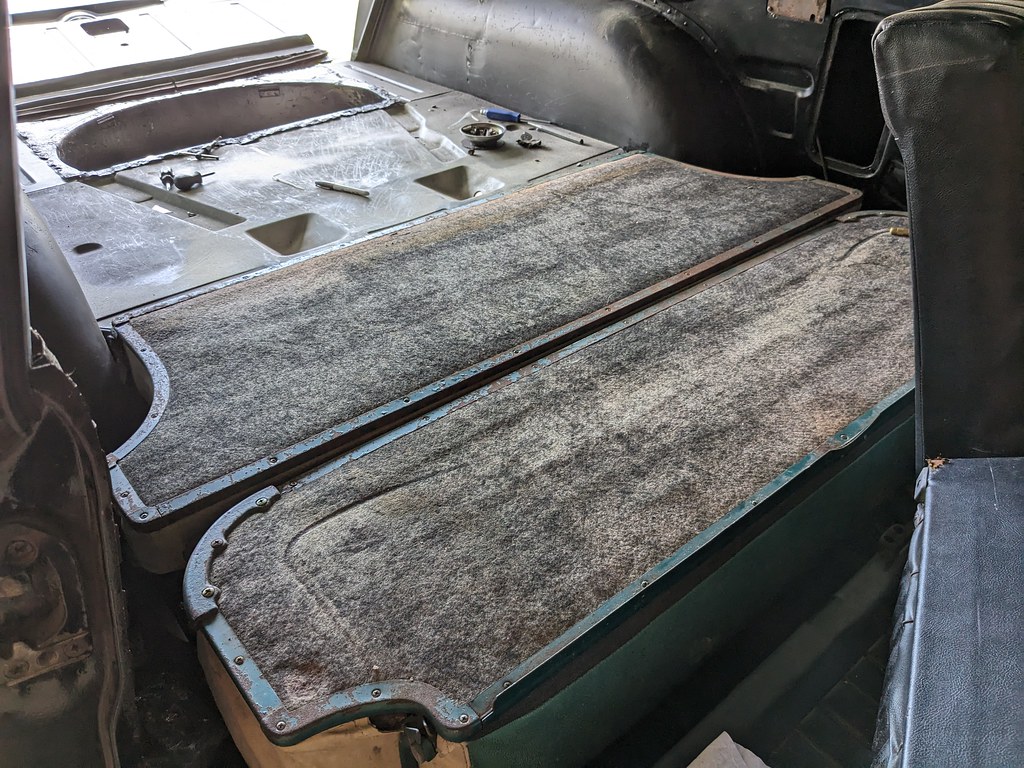
I was also tinkering around with the seat bracket placement and think that I've nailed down the seat bottom, but need to finalize the location for the upper hinge brackets. I drilled the lower brackets with self tapping screws to tighten it to the floor and the seat flips up and down nicely. The upper will be more difficult because it needs to pivot at the right location to both hit the upper latches and lay flat and not too far forward in the down position.
I sharpened all my tig tungsten, so hopefully I'll get the recess panel built and welded in this week.
Cheers,
Ryan
Moving forward, I was able to get the transmission crossmember mocked up and it's going to work great with the right driveline angles. It does still need to be tilted up about a 1/2" more, but there is a lip in the tunnel that needs a little BFH work.

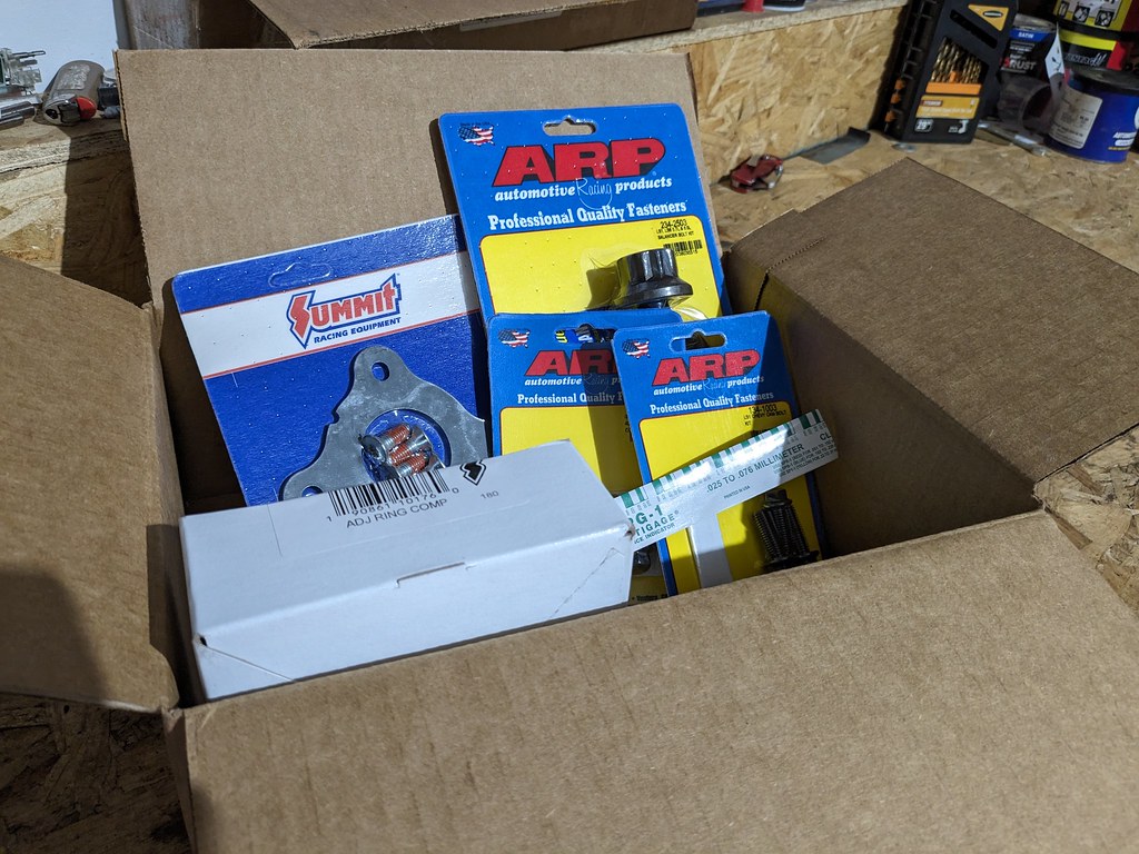
I placed an order from Summit and got the rest of the bolts, gaskets and a new piston ring compressor to get the short block finished up. I'm going to be gapping the rings for boost because down the road I'll be adding a turbo, or possibly an LSA supercharger. I've got a buddy doing an LSA swap right now and it's making me want to put on on this car too...

Since the engine is still mocked in the car, I was side tracked with my fuel system. My plan from the beginning was to use a stock fuel pump to have the most reliability, and my experience with the 10-15 Camaro SS fuel pump was fantastic. Vaporworx sells a conversion kit to allow them to run at a fixed 58 or 43 psi with a kit. So that was my plan, but after I decided to use the wagon fuel tank that pump is way too short. The CTSV and SS Camaro fuel pump assemblies only go to about 7.25" tall and my tank with a recess panel for the pump needs to be about 11" tall. After some thought, I decided that I'd buy an SS pump and build my own pump using other parts I have acquired. I've nicknamed this the "Frankenstein Pump" since it will be made using so many different parts. CTS-V fuel hat, Silverado rods/springs, SS Camaro fuel pump lower section and 4th gen Camaro fuel pressure regulator.
Now, before someone chimes in and says I should have just bought the PWM kit to control the fuel pump that did cross my mind. However, I've still got so many other parts to buy and that money could be used for other things right now and I already had the fixed pressure adapter. Plus I like a good challenge and if it keeps me on track with my budget, it's a win-win.
I did this several weeks ago, but I started off with the first wagon tank that I picked up for really cheap and used that as my test tank. I cut a hole in it where I new I wanted the fuel pump and made sure that this whole project would even be possible. It's a very tight spot where the fuel pump fits flush on the bottom of the tank, but it fits and that's what's most important. Time to collect parts.

While I was figuring out what rods to use for when I extended the SS fuel pump, I came across a new Delphi pump out of a 09-13 Silverado for crazy cheap on eBay. It also came with a new green seal, so I picked that up for $35 bucks.

Also on eBay I found a wrecking yard selling a 13 SS fuel pump with 40k miles and they accepted my offer for $45 bucks. I now had all the parts for my "Frankenstein Pump".

First step was to disassemble the two pumps. First up was the SS fuel pump. There is an inner assembly that is held in with some clips that had to be popped out to remove the clips for the top lid to come off.

After I robbed the rods from the Silverado pump, I did a quick test fit using the SS Camaro top fuel lid and it gave me the height that I needed at full compression. I bought a new 10mm corrugated hose a while ago because I was pretty sure I was going to be doing this project at some point. It fits perfectly for this application.


While I liked the SS fuel hat better, where the rods are held in was a press fit and too loose to fit the longer rods. I had a spare CTSV fuel hat from my Camaro and that was a perfect fit. And there were slots in the SS pump lower section for the rods to go since the rod spacing is different between the SS and CTSV.

Now that it's all fitting together nicely, it's time to work on the fitment into the fuel tank. Glad that I had a spare tank to play with since I cut this one too far on the vertical side. Perfect for getting me measurements though.


I also wanted to make sure that there would be enough room for me to get a tool around the fuel pump ring.

At this point, I'm completely satisfied with the fitment of this pump in the tank so I took some measurements off the test tank and transferred them to my good tank. I made sure that my cuts were way smaller than needed to be so that I could creep up on the final cut lines.


I wanted to play around with some cardboard to see what the recess panel will look like and fit. Now because there was such a tight fit for where the fuel pump had to be placed, I wanted to make sure that the recess panel was centered as perfectly as I could get it. I build the recess panel template and used the inner inner diameter of the locking ring for my initial hole. With the template fitting snuggly on the top of the fuel pump hat I placed the pump in the exact spot it needed to be in the fuel tank. That centered up the template and allowed me to make some marks for my final cuts.


Now that I confirmed the fuel pump is exactly where I wanted it, I cut the hole larger to test fit the actual fuel pump ring I'll be using and once again checked the fitment.


I'm very pleased with the fitment and there should be plenty of clearance above the fuel pump. With it all in place, it was now time for the first test fit in the car.

Huge fail!! But this is why I've come to realize that test fitting parts before a final weld or assembly is so important. While there is plenty of space above the fuel pump, there isn't anywhere for the fuel line to go.


I marked where it needed to be for a fuel line to be, then pulled it out and started over. I had to make a new template because the old one wasn't long enough on the sides. trimmed the tank about 3/4" lower then reinstalled for a second test fit. It's perfect now and I'm very pleased.


Miles of room above the fuel hat.

Here's the final mock up. One minor adjustment I'll need to do is shorten the rods just slightly because they are just a touch too long now that I had to lower the recess panel. That will be a very quick process, but here's the completed fuel pump. Next up will be transferring my template to metal and getting it welded in place.

My buddy Jonathan said that my fuel pump looks a lot like the tornado machine from Twister. So I added a mark for Dorothy IV haha

I was also tinkering around with the seat bracket placement and think that I've nailed down the seat bottom, but need to finalize the location for the upper hinge brackets. I drilled the lower brackets with self tapping screws to tighten it to the floor and the seat flips up and down nicely. The upper will be more difficult because it needs to pivot at the right location to both hit the upper latches and lay flat and not too far forward in the down position.

I sharpened all my tig tungsten, so hopefully I'll get the recess panel built and welded in this week.
Cheers,
Ryan
The following users liked this post:
ryeguy2006a (08-15-2023)
The following 3 users liked this post by Mr. Black:
The following users liked this post:
ryeguy2006a (08-22-2023)
#95
Thread Starter
Joined: Apr 2012
Posts: 2,032
Likes: 594
From: Ruckersville, VA
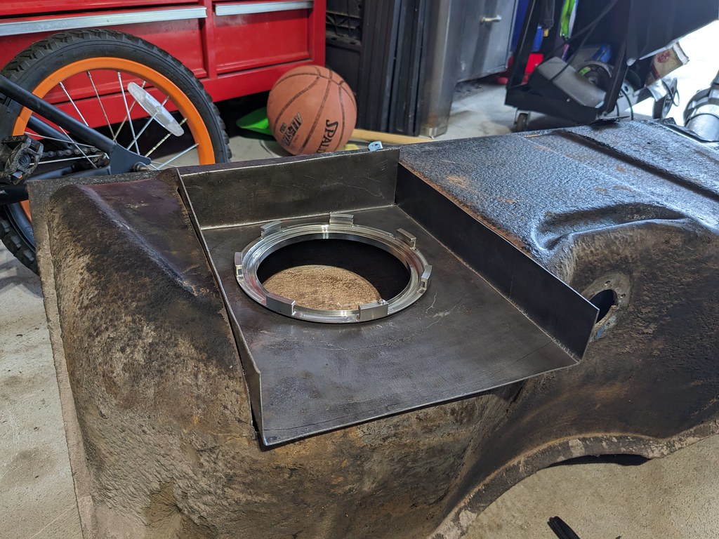
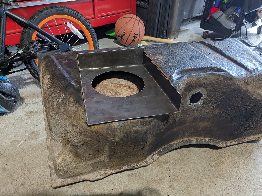
Been busy working on the car, but have been sidetracked practicing my TIG welding. My plan is to weld the 304 SS fuel ring to my mild steel fuel recess panel and what a great opportunity to get better with the TIG. I first wanted to practice on some coupons and scrap pieces I had so that the finished product would be at least halfway decent. I practiced a while and then did a test run on the outside corner joints, and that's when I realized that I needed a lot more practice. Then I went down a bit of a rabbit hole and was practicing TIG in pretty much all my free time.

While the weld is solid and won't leak, it needs a lot more attention to cleanliness, consistency and better pedal/filler control. Now that the corners were welded and the recess was built, I was able to confirm the pump will work like I need it to. I need to practice more with my TIG before I attempt the final weld on this piece.
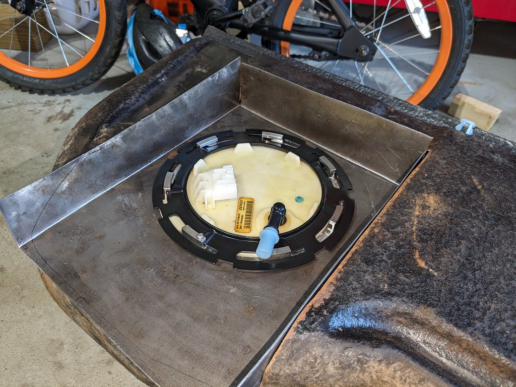
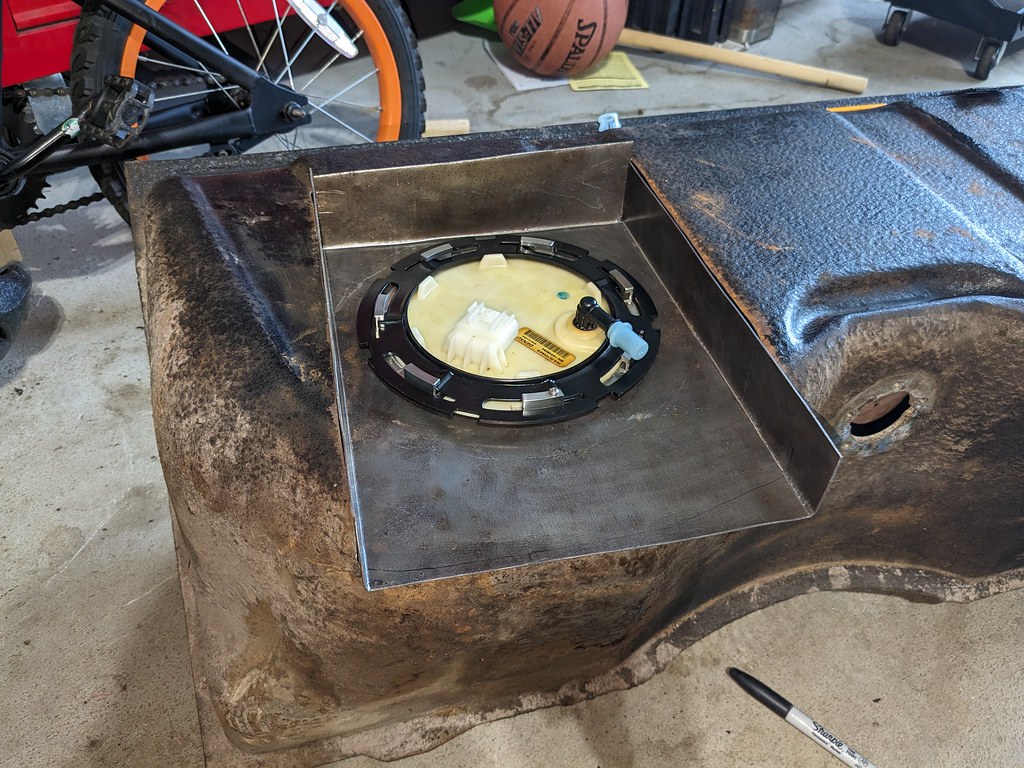
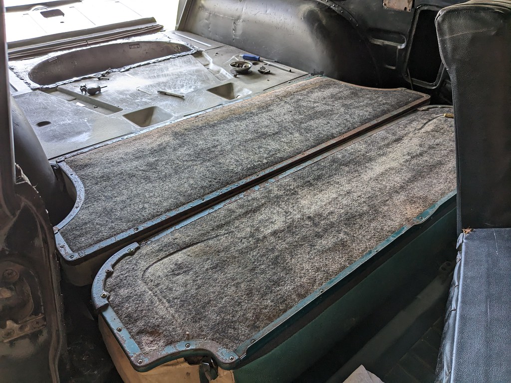
Other than practicing my TIG welding, I did get the rear seat locations finalized. I thought the upper seat would be the easy part, but I was very wrong. It took way more effort than I realized to locate the lower hinges, since they need to match up with both the rear cargo surface and the lower seat mount. After lots of choice curse words and lots of extra holes in my newly welded in wheel wells, I found a location that I'm happy with. Now that it's final, I'll need to build some reinforcement plates for the hinges that will weld in from the inner wheel well.

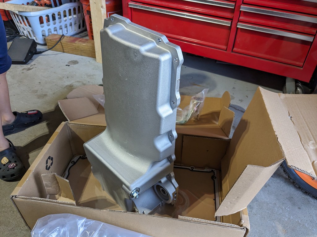
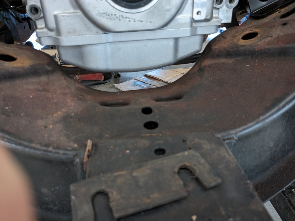
A few weeks ago I was talking to my father-in-law about how I was disappointed that my 302-2 oil pan didn't fit and that I needed to buy a 302-1 pan. Well a few days later a 302-1 pan showed up on my doorstep! What a nice surprise! Thanks Bern! Before I removed the motor to tear it down, I wanted to confirm that it would fit in the current location or if I'd need to adjust the engine mounts forward or back. Thankfully, I made a good guess when I installed the mounts and it all fits really well. 302-1 pan has all the clearance where I need it!
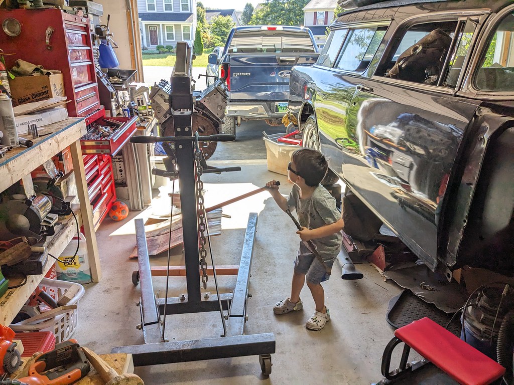
My boys are always in the garage helping me out. You can see his crocs in this picture.

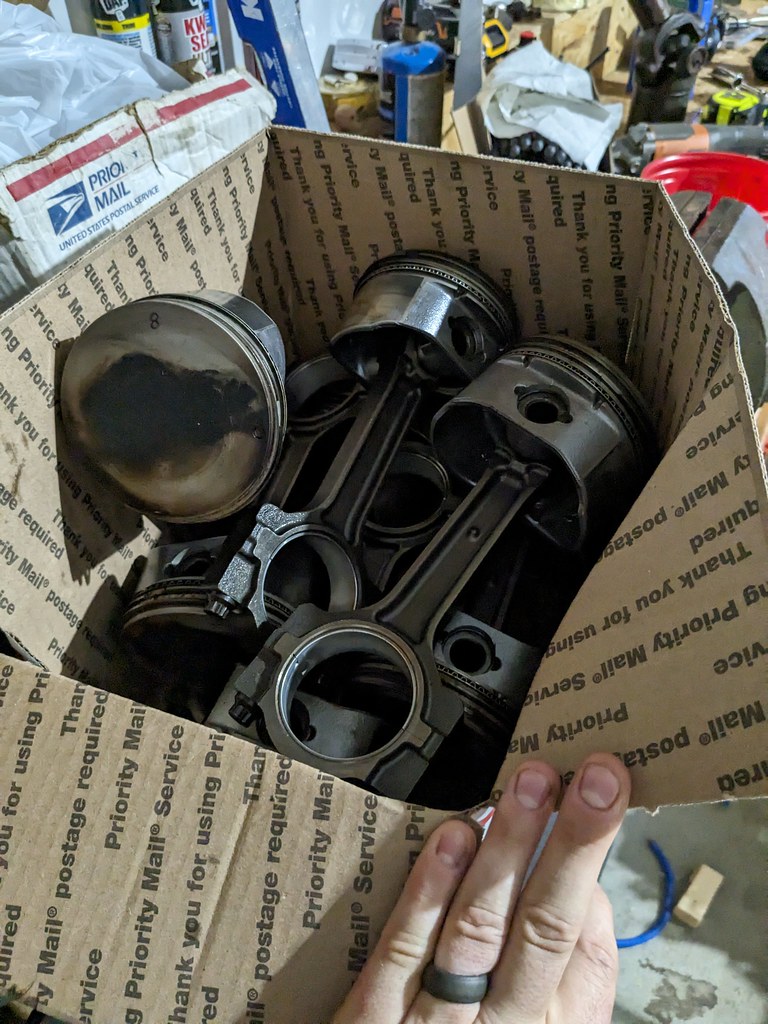
Now that everything fits like it needs to, I pulled the motor/trans and got the engine torn down. I'm only pulling the pistons/rods so that I can gap the rings for when I add a turbo down the road. All the bearings looked good, so I'll reinstall them once carbon buildup is cleaned off the pistons and the ring gap is opened up. I'm planning on .030" on both top and second ring.
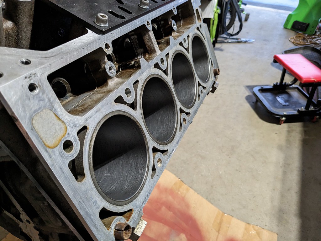
I deglazed the cylinder walls and restored the cross hatching. Now I'm ready to start cleaning up the pistons and gapping the rings one by one.
That's all for now. I'm hoping to get to a point this week where I'm happy with my welds so that I can weld up the modified fuel tank. Then I'll order the rest of my engine parts and get that put back together.
Cheers,
Ryan

While the weld is solid and won't leak, it needs a lot more attention to cleanliness, consistency and better pedal/filler control. Now that the corners were welded and the recess was built, I was able to confirm the pump will work like I need it to. I need to practice more with my TIG before I attempt the final weld on this piece.


Other than practicing my TIG welding, I did get the rear seat locations finalized. I thought the upper seat would be the easy part, but I was very wrong. It took way more effort than I realized to locate the lower hinges, since they need to match up with both the rear cargo surface and the lower seat mount. After lots of choice curse words and lots of extra holes in my newly welded in wheel wells, I found a location that I'm happy with. Now that it's final, I'll need to build some reinforcement plates for the hinges that will weld in from the inner wheel well.


A few weeks ago I was talking to my father-in-law about how I was disappointed that my 302-2 oil pan didn't fit and that I needed to buy a 302-1 pan. Well a few days later a 302-1 pan showed up on my doorstep! What a nice surprise! Thanks Bern! Before I removed the motor to tear it down, I wanted to confirm that it would fit in the current location or if I'd need to adjust the engine mounts forward or back. Thankfully, I made a good guess when I installed the mounts and it all fits really well. 302-1 pan has all the clearance where I need it!
My boys are always in the garage helping me out. You can see his crocs in this picture.


Now that everything fits like it needs to, I pulled the motor/trans and got the engine torn down. I'm only pulling the pistons/rods so that I can gap the rings for when I add a turbo down the road. All the bearings looked good, so I'll reinstall them once carbon buildup is cleaned off the pistons and the ring gap is opened up. I'm planning on .030" on both top and second ring.

I deglazed the cylinder walls and restored the cross hatching. Now I'm ready to start cleaning up the pistons and gapping the rings one by one.

That's all for now. I'm hoping to get to a point this week where I'm happy with my welds so that I can weld up the modified fuel tank. Then I'll order the rest of my engine parts and get that put back together.
Cheers,
Ryan
The following users liked this post:
patman2 (08-28-2023)
#96
Thread Starter
Joined: Apr 2012
Posts: 2,032
Likes: 594
From: Ruckersville, VA
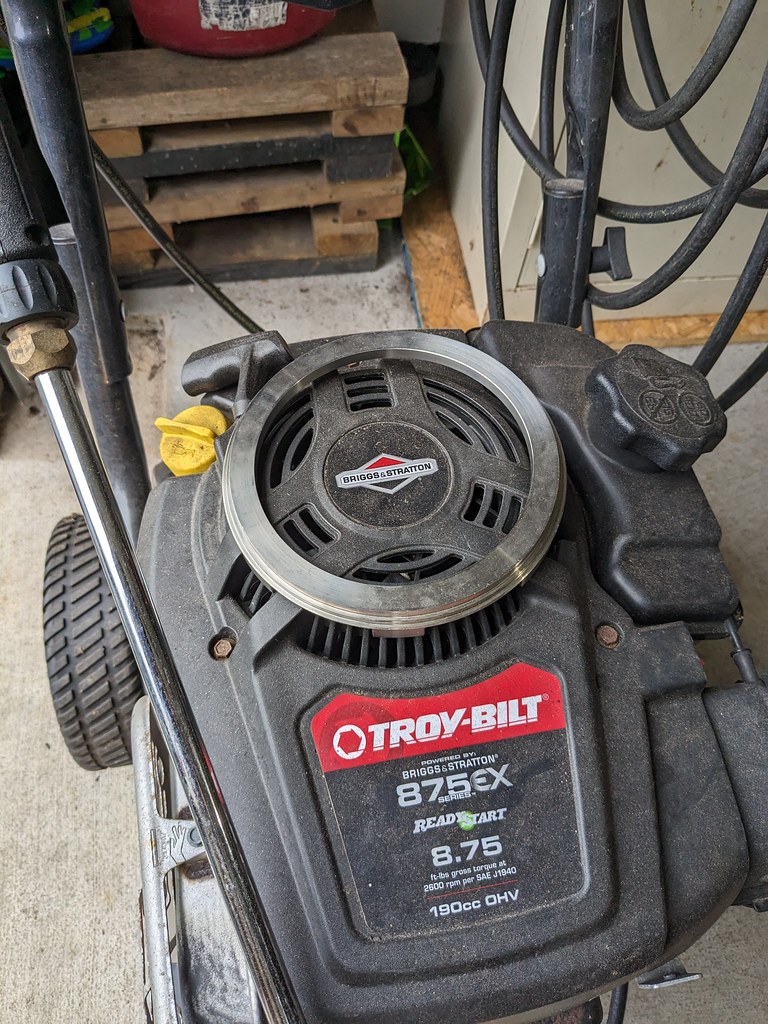
After practicing on many coupons, I felt comfortable enough to start welding my Stainless ring to the mild steel fuel recess panel. Then I went to find the fuel pump ring and it was no place to be found. My youngest son (4 YO) loves being in the garage with me and will take things from my bench regularly. I asked him and he had taken it off my bench and he had no idea what I was talking about. Well after pulling my hair out for 15 mins looking, I finally found it. Now, I don't remember putting it on the power washer haha.
Now that the ring was located it was time to weld. The welds were pretty ugly, but they are solid penetration and if anything maybe a touch too hot. I started by tacking the ring to the panel and did one more test fit before final welding.
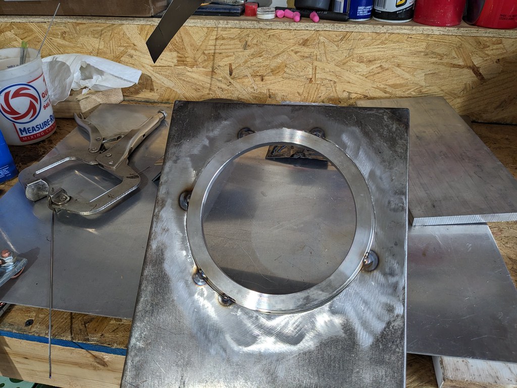
After I confirmed that the recess was still were I wanted it to be in the tank, I flipped the recess over and welded everything from the bottom side. I figured that my welds will be much better hidden where no one can see them haha. I welded about 1.5" at a time and then moved to the other side of the ring and let it cool. One thing I read about stainless is that it has a tendency to warp when it's being welded. So I wanted to minimize that as much as I could. Once it cooled, I test fit another time just because.
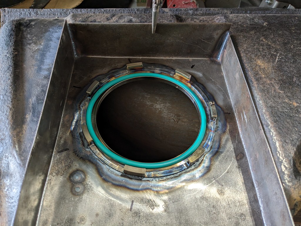
I started on the front and rear of the tank and tacked them in a few spots. The open side did warp up slightly, but I was able to tack in the center and bring the sides down flush.

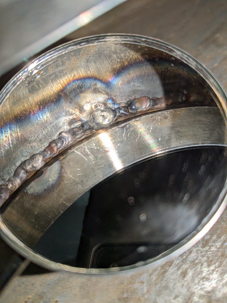
The entire perimeter of the recess is now fully welded! What I love about TIG welding is that I was able to weld a lot of this panel with no filler wire, just melted it together with the existing materials. Very pleased with the results, but the real test was whether it leaked!
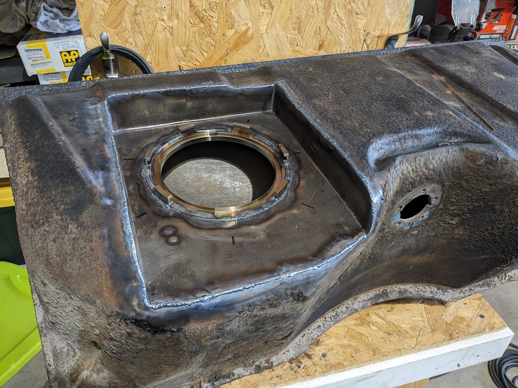
I didn't have a good way to seal off all of the ports in the tank, so I tipped it on the side with a spare fuel hat I had and looked for any leaks. Unfortunately I had a pin hole leak in the fuel ring area. I wasn't sure how I was going to fix that, but after some thought, I taped up the front of the recess and filled with water up to the ring. Worked like a charm and I found the little pinhole from the inside. I was able to stuff my TIG torch into the tank and welded it from the bottom with a mirror. There was more than enough filler, so I just had to create a puddle around the pinhole to fill it. Retested and no leaks! Left it for about 15 mins and still dry as a bone. WIN!
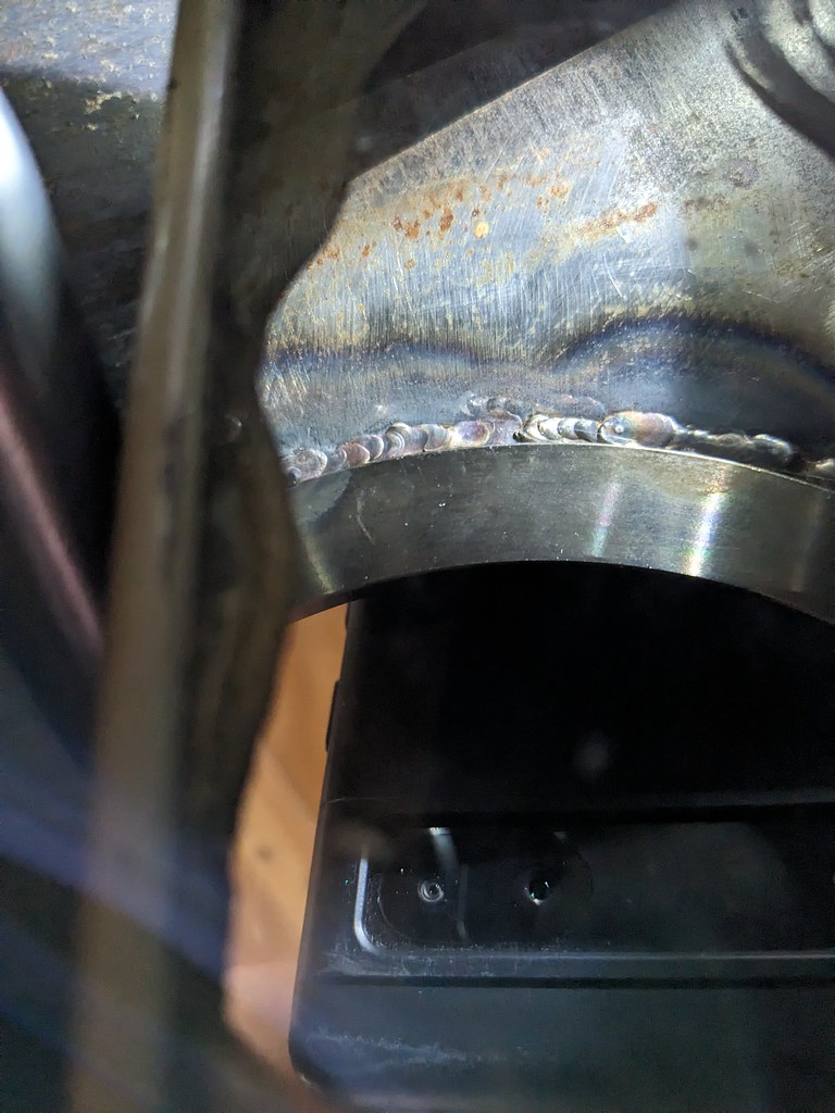
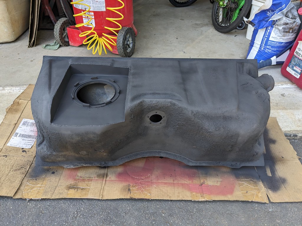
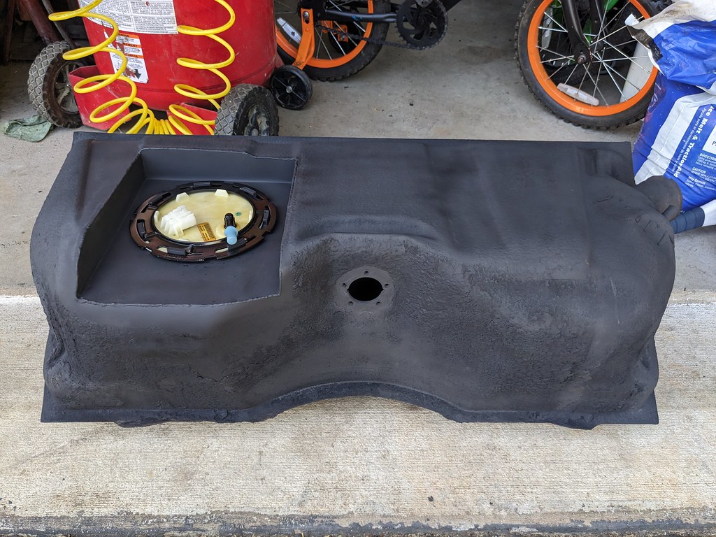
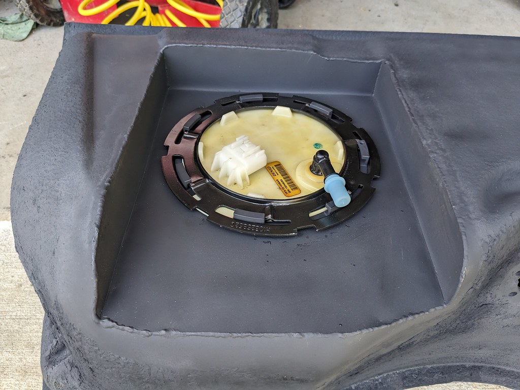
Once I confirmed no leaks, I got it all painted up and ready to install.

Glad that project is behind me. Moving on, I wanted to get the rings gapped and reinstalled. While the pistons were out, I also cleaned them up with some Seafoam and a scotchbrite pad. Worked much better than purple power that I had used in the past. Then one by one I pulled the top and bottom rings off the pistons to first measure them. Most of them came in around .023 top and .025 second ring. Interesting because the guy I bought the motor from said they were gapped for N/A..., but I have a feeling that it may have been boosted at some point. Regardless, I gapped them to .028 top and .030 second ring. I did have to consult with my resident expert. Here he is explaining to the neighbor kid how to use the ring grinder haha. I built him a workbench last year and it works great for me too. I just have to move his tools off of it before I use it.
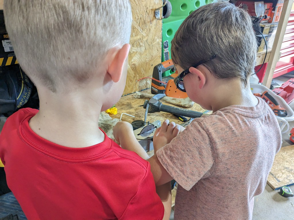
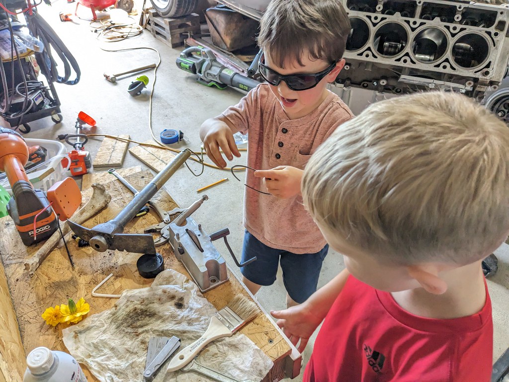
After I confirmed I was doing it right, I reinstalled the pistons/rods and got them all torqued down.
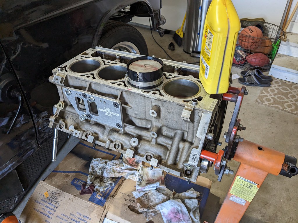
I reinstalled the pan just to keep the dust out, but I'll need to pull it back off to install the oil pump, windage tray and pick up tube.
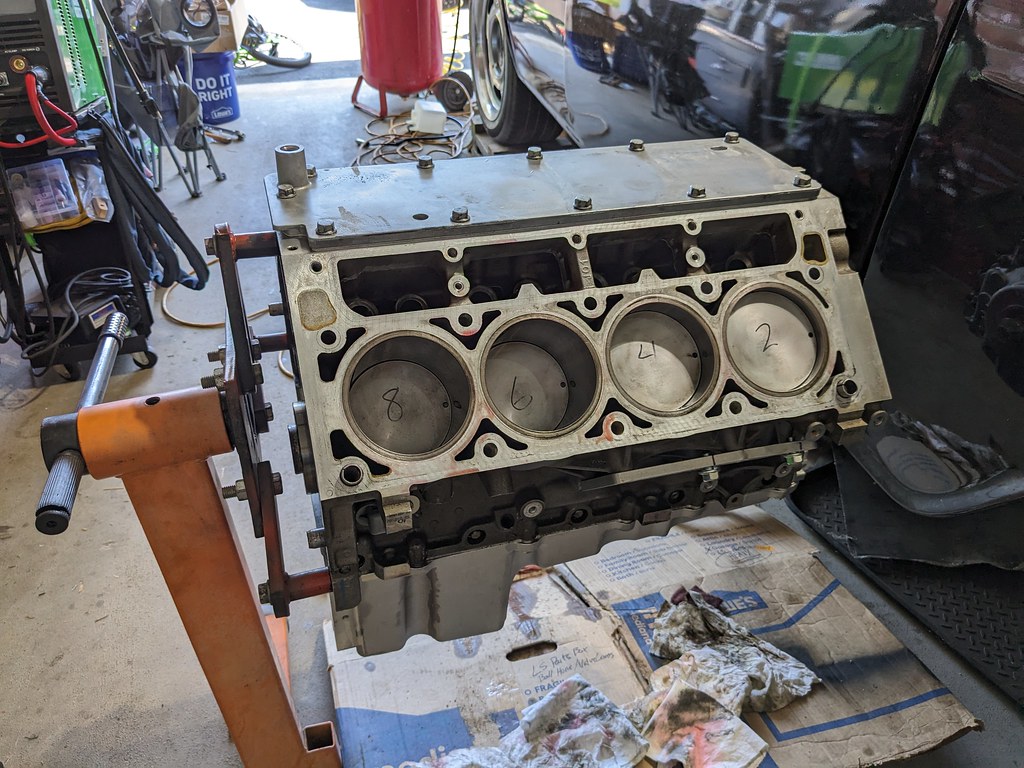

Overall pretty productive weekend. I ordered some engine parts that are supposed to be here today. Once those are here, I can get the cam installed and the heads back on once I clean those up. I'll also need to get the fenders pulled off so that I can paint the firewall before I put the motor back in.
Cheers,
Ryan

Now that the ring was located it was time to weld. The welds were pretty ugly, but they are solid penetration and if anything maybe a touch too hot. I started by tacking the ring to the panel and did one more test fit before final welding.

After I confirmed that the recess was still were I wanted it to be in the tank, I flipped the recess over and welded everything from the bottom side. I figured that my welds will be much better hidden where no one can see them haha. I welded about 1.5" at a time and then moved to the other side of the ring and let it cool. One thing I read about stainless is that it has a tendency to warp when it's being welded. So I wanted to minimize that as much as I could. Once it cooled, I test fit another time just because.

I started on the front and rear of the tank and tacked them in a few spots. The open side did warp up slightly, but I was able to tack in the center and bring the sides down flush.

The entire perimeter of the recess is now fully welded! What I love about TIG welding is that I was able to weld a lot of this panel with no filler wire, just melted it together with the existing materials. Very pleased with the results, but the real test was whether it leaked!

I didn't have a good way to seal off all of the ports in the tank, so I tipped it on the side with a spare fuel hat I had and looked for any leaks. Unfortunately I had a pin hole leak in the fuel ring area. I wasn't sure how I was going to fix that, but after some thought, I taped up the front of the recess and filled with water up to the ring. Worked like a charm and I found the little pinhole from the inside. I was able to stuff my TIG torch into the tank and welded it from the bottom with a mirror. There was more than enough filler, so I just had to create a puddle around the pinhole to fill it. Retested and no leaks! Left it for about 15 mins and still dry as a bone. WIN!


Once I confirmed no leaks, I got it all painted up and ready to install.


Glad that project is behind me. Moving on, I wanted to get the rings gapped and reinstalled. While the pistons were out, I also cleaned them up with some Seafoam and a scotchbrite pad. Worked much better than purple power that I had used in the past. Then one by one I pulled the top and bottom rings off the pistons to first measure them. Most of them came in around .023 top and .025 second ring. Interesting because the guy I bought the motor from said they were gapped for N/A..., but I have a feeling that it may have been boosted at some point. Regardless, I gapped them to .028 top and .030 second ring. I did have to consult with my resident expert. Here he is explaining to the neighbor kid how to use the ring grinder haha. I built him a workbench last year and it works great for me too. I just have to move his tools off of it before I use it.


After I confirmed I was doing it right, I reinstalled the pistons/rods and got them all torqued down.

I reinstalled the pan just to keep the dust out, but I'll need to pull it back off to install the oil pump, windage tray and pick up tube.


Overall pretty productive weekend. I ordered some engine parts that are supposed to be here today. Once those are here, I can get the cam installed and the heads back on once I clean those up. I'll also need to get the fenders pulled off so that I can paint the firewall before I put the motor back in.
Cheers,
Ryan
The following 4 users liked this post by ryeguy2006a:
The following users liked this post:
ryeguy2006a (09-14-2023)
#98
Thread Starter
Joined: Apr 2012
Posts: 2,032
Likes: 594
From: Ruckersville, VA
Only thing left for the shortblock to be finished is flipping it over and doing a final torque on the rods. They all have one ugga right now
 Next up was getting the heads disassembled and inspected. Thankfully the valves were all straight and in great shape. The seats all looked great, but I lapped a few of them that had a little pitting on the exhaust valves. Overall very pleased with the condition. Once I got a bare head, I started to clean them up with some purple power.
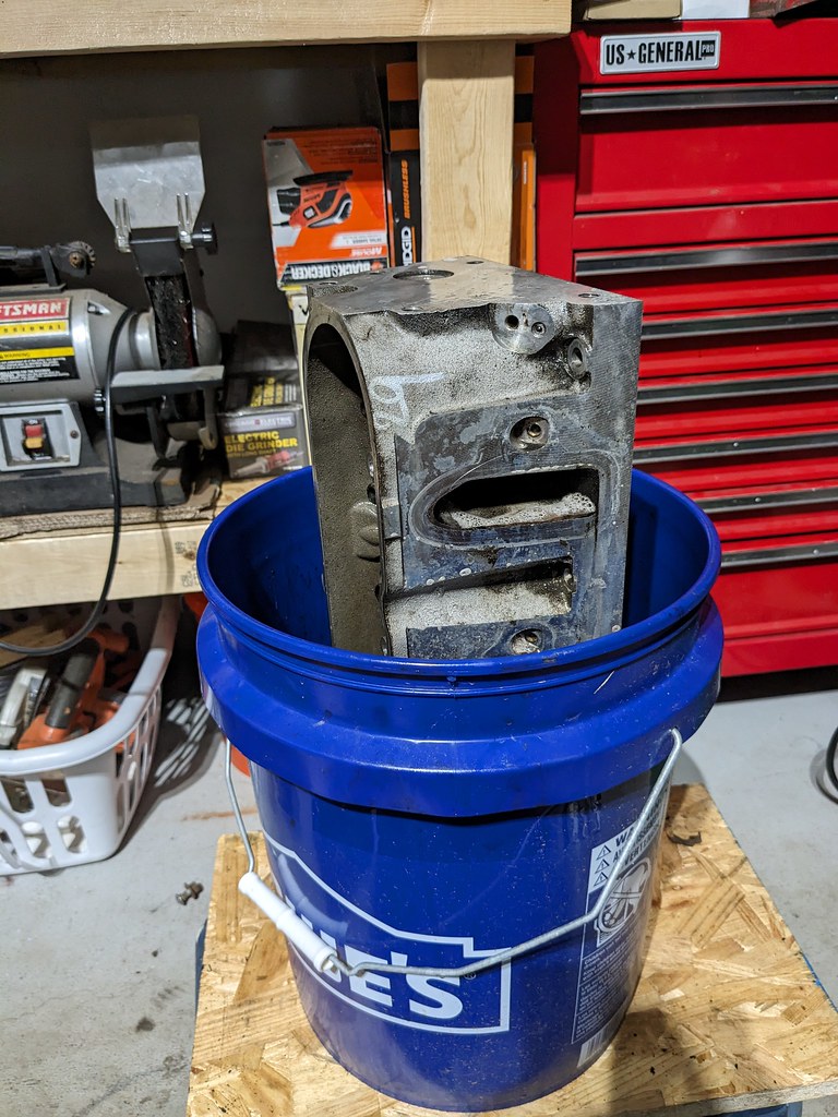
The purple power did a great job on most of the grime, but inside the intake ports and a little around the valve in the combustion chamber was a thick tar like carbon build up. The purple power didn't do a good job of cleaning it. Then I tried some Seafoam, which did an ok job, but dissolved it quite slowly. I had a bottle of this stuff called LA Awesome that I had read about on a forum and picked it up a year and a half ago. I tried some of that in a spray bottle and WOW what a difference. The tar practically melted off when used with my brass scrub brush. LA on the left and purple on the right. I'm sold on the stuff.
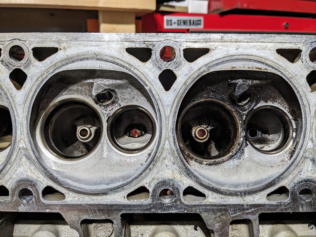
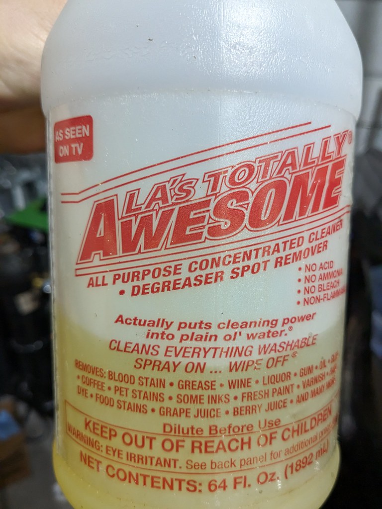
I cleaned up 90% of the carbon and called it good. It's going to get gummed back up so I'm not spending more time on it. Since I'm going budget on this build, I found a set of LS3 valve springs from my Camaro, and decided to use those. I also soaked the intake and exhaust valves to clean them up and the LA did a fantastic job of melting off the grime. It all went together pretty quickly.
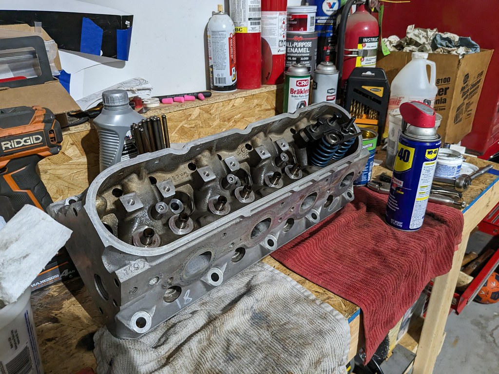
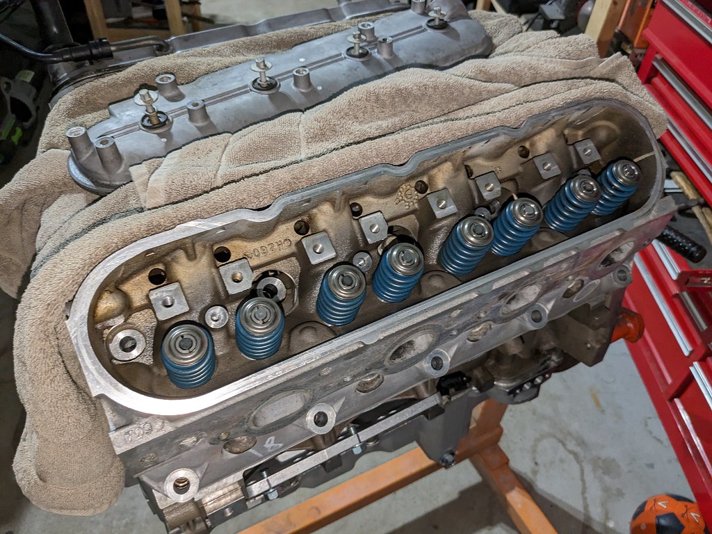
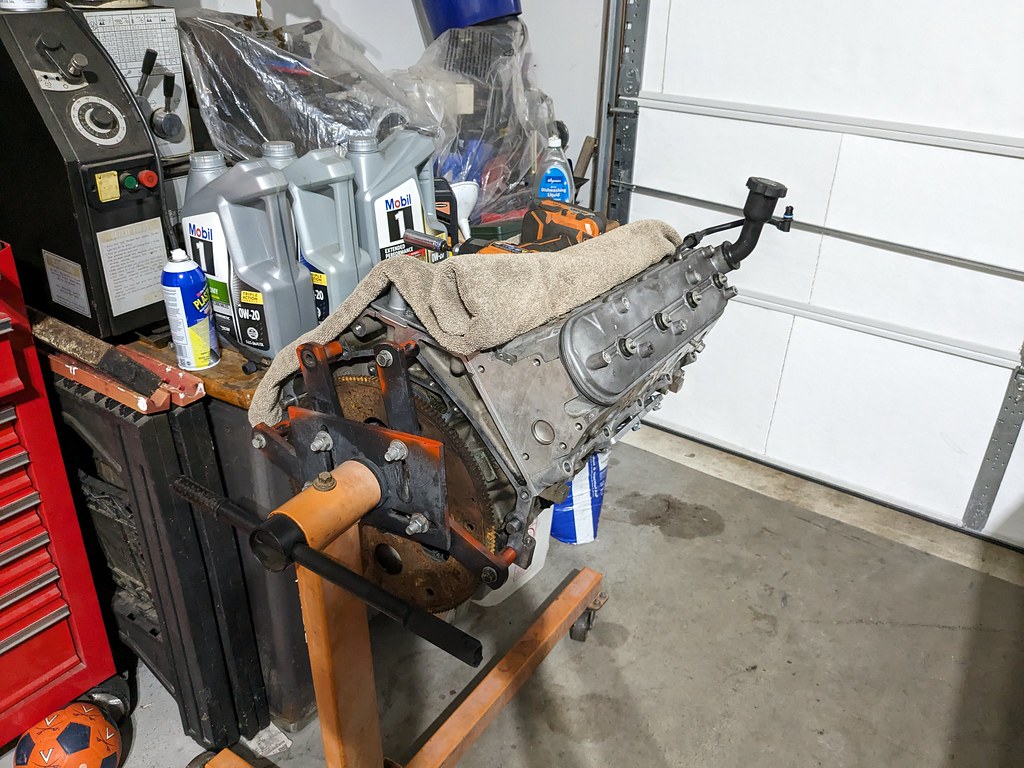
I didn't get any pictures, but the driver's side head went together just as nicely and the heads are back together. I've got a set of ARP head bolts on the way and will hopefully get this engine back together this weekend. Since the engine is going to be done soon, it was time to address the firewall and get that prepped. At some point in it's life, someone painted the firewall a nice red color. It's nice, but not with a black car, so I pulled the fenders off to get it prepped for some satin black.
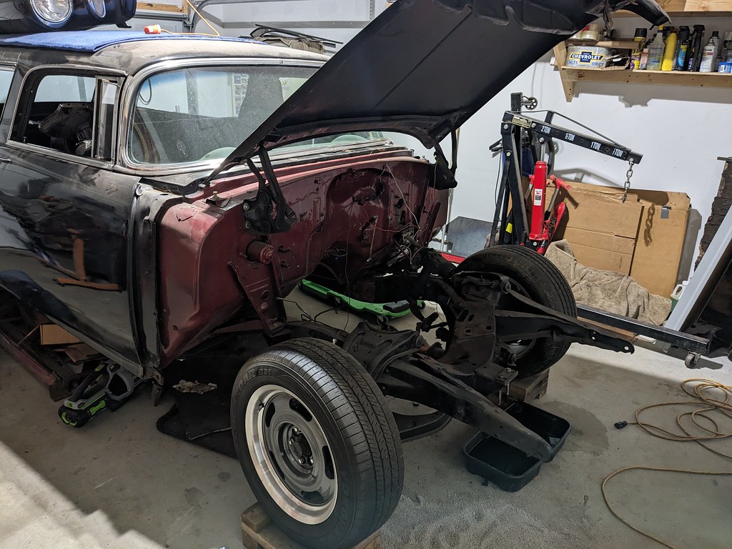
I'm not spending a ton of time here, just scuffing it down and primed black.
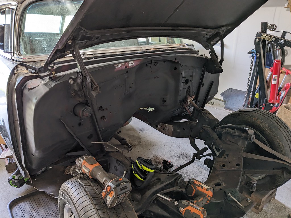
There were a few pinholes that I welded shut at the top of the cowl. Hit with a flap disk and good as new, then a second coat of primer.
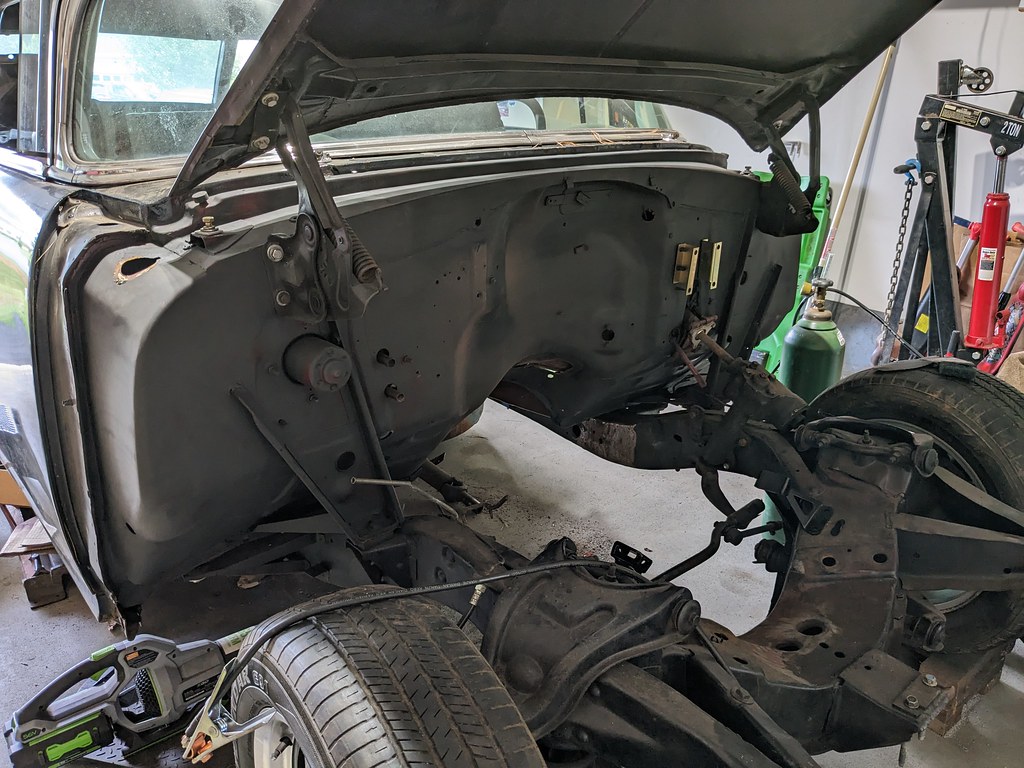
I masked up the rest of the car and hit everything with a scotch brite pad for good adhesion.
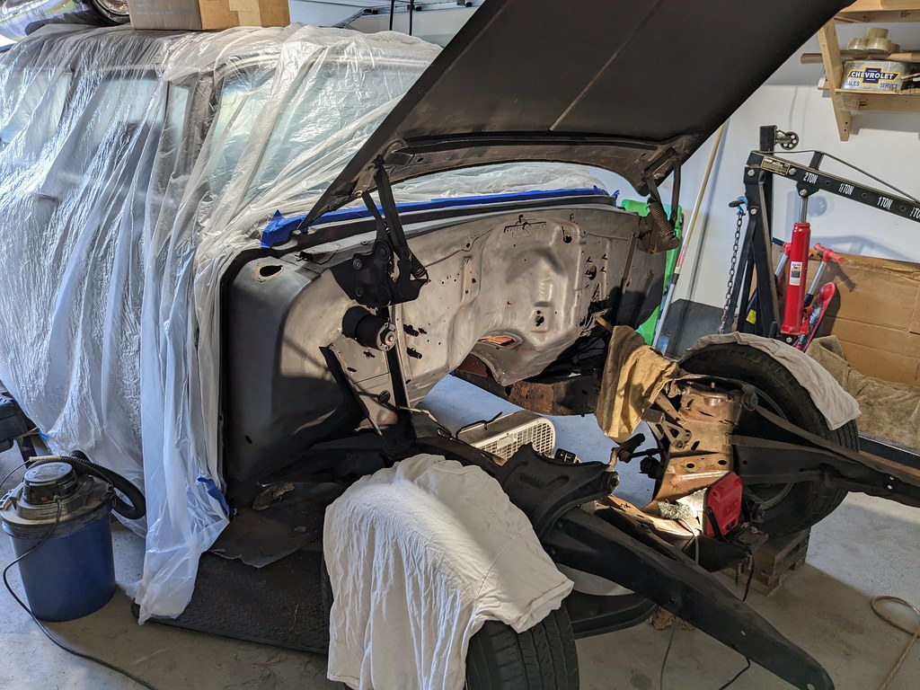

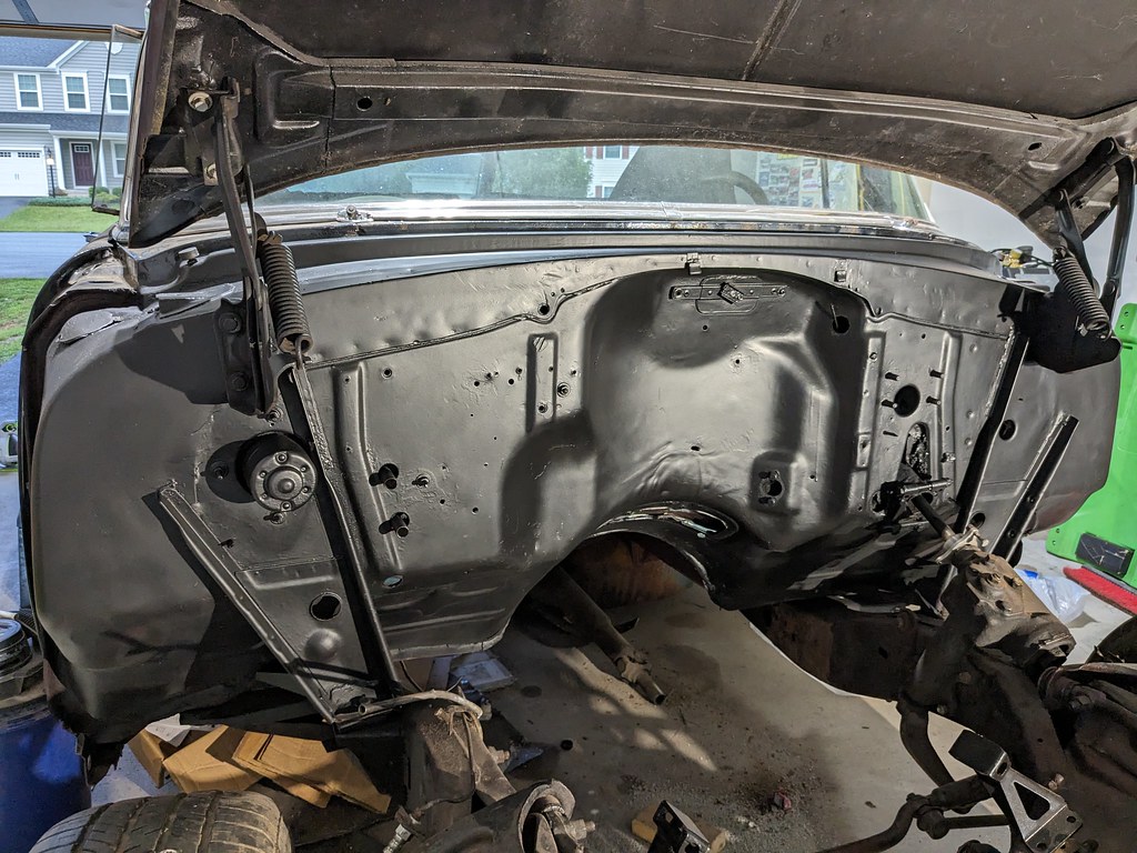
After it was all prepped, I sprayed with a light coat of SEM Trim Black, then went back with a medium-heavy coat. I'm very pleased with how it turned out for the amount of time I have in it. I have to keep reminding myself that I'm not doing a full on restoration. I just want to clean it up to be presentable with my main focus on getting it to be a functional driver. I put my Camaro up for the winter in 2021, and then sold it in 2022, so it's been almost two years without something cool to drive! Way too long.
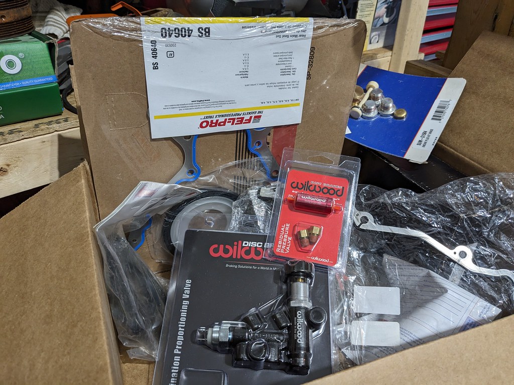
Well now that I've got everything I need for my engine to run, I need to focus on my brakes. I placed an order with Summit earlier in the week and they got my parts to me in 2 days! Very quick. Wilwood proportional valve, drum brake 10 lb residual valve, rear differential brake hose, and Summit Brand line lock. Also have the remaining gaskets and seals for my engine.
I've also pulled out my Tesla Model S iBooster to see what it's going to take to get this mounted to my firewall. I'm likely going to go in the same direction Andrew did and modify the brackets I have to work.
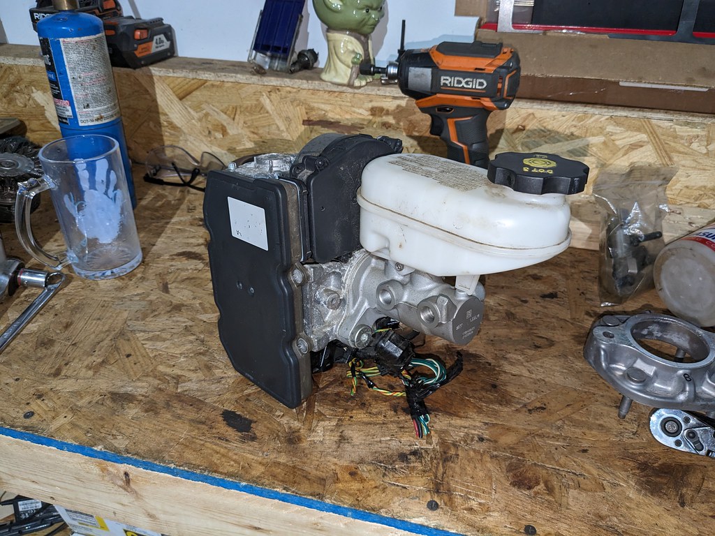
I'm getting very excited about this next stage in the project. My goal is to mount the engine/trans in place and get it all back together by the end of the weekend. I still need to clean up and paint the frame sections that are exposed, and get the side mounts bolted down for good. If I can get that done and lay out the Terminator X, I just might have a chance of firing the motor by the end of next week or next weekend!
Cheers,
Ryan
The following users liked this post:
ryeguy2006a (09-18-2023)
#100
Thread Starter
Joined: Apr 2012
Posts: 2,032
Likes: 594
From: Ruckersville, VA
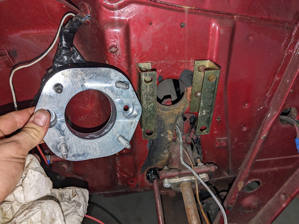
After looking at the brackets and thinking on it for a few nights and looking at Andrew's swap, I was going to mount the brackets to the booster. Then I'll figure out how to get them attached to the car. I drilled a new hole on each of the brackets to match the iBooster bolt pattern. With everything loosely tightened up, the brackets have enough room to bolt up. I think I'm going to attempt to bent the brackets slightly in each direction so that the rear bolt pattern matches the stock Bel-Air pattern. I just wanted to get it mounted up to see if I liked the look, or if it needs to be angled up.


I really like the way that it's fitting, but I think that it needs to be tilted up slightly. I'm not sure if I'll attempt to make my own brackets, or modify the ones that I have. I need to think on it more. Great news it that it lines up with the brake pedal perfectly!
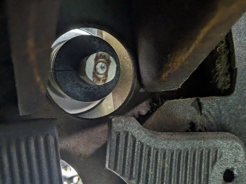
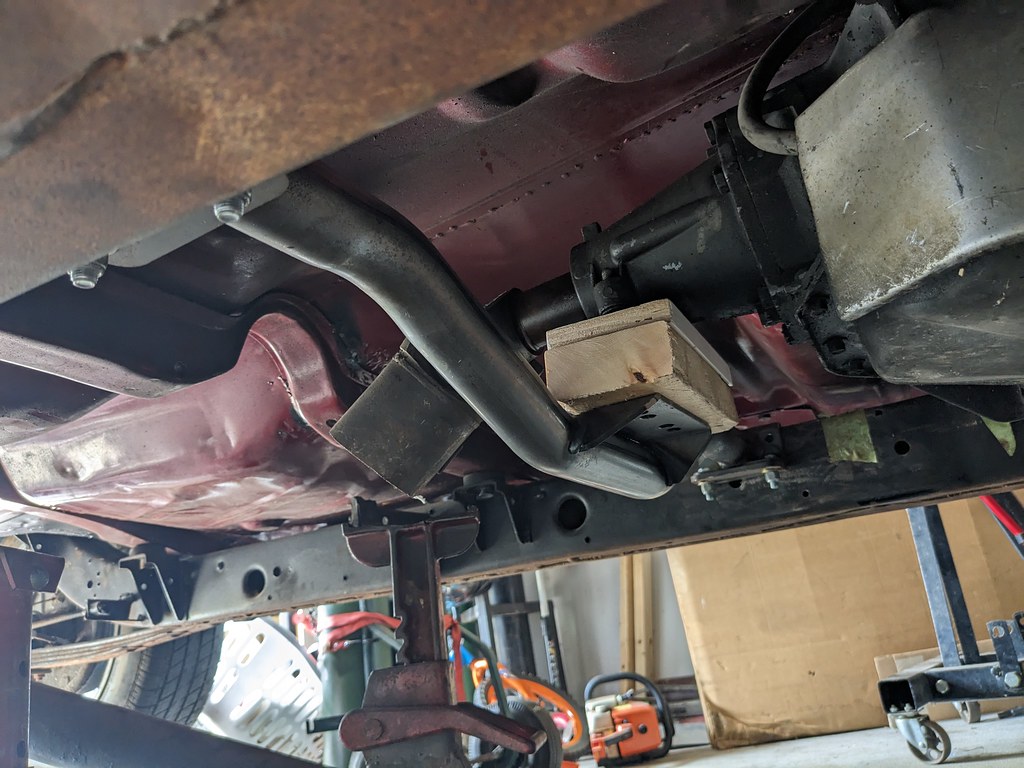
As I usually do, I was checking FB marketplace and found a guy giving away a DFP delete pipe for a 2011 F250. I know that I wanted a 4" pipe for when I swap on the turbo, so this will work perfectly. It's 409 SS so it does have some slight surface rust, but I should be able to clean that up. Now I'll keep an eye out for a turbo log manifold and downpipe. If I can score a deal on them in the next month or so, I'll make turbo placeholder pipe and plumb it all together. That way when I'm ready I'll just swap out the "fake turbo" for a real one haha. No point in spending money for a full dual exhaust when I'll be replacing it in the short term.

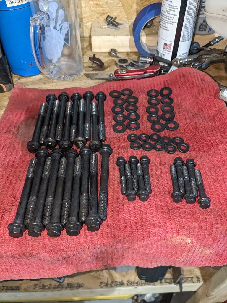
I received the last bolts that I needed to assemble the engine, so I got back on that. Head bolts and lifter retainer bolts. Got a deal on a set of once torqued ARP head bolts from an engine that was disassembled before it ran.
My plan all along has been to put this engine together on a fairly tight budget, and I had been planning to install a stock LS1 cam that I picked up from a buddy. In the end I just couldn't do it. I started looking for some low lift cams and stumbled on the SDPC LS6 Powermax PLUS Cam. It works perfectly with the LS3 springs I have as it's a fairly low lift cam at .570" . It's a 220/222 on a 112 LSA. While this cam won't make the most HP out there, it was only $269 shipped and worked with springs that I already had. Should make a nice street cam.

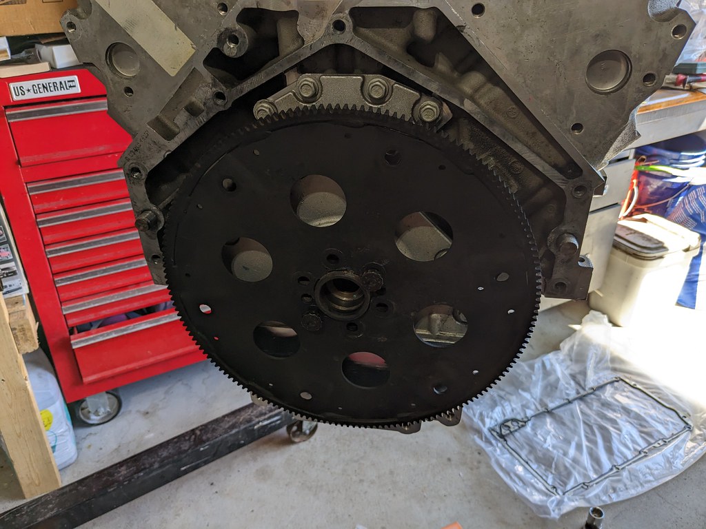
I started by installing the rear cover and gasket. I put a new main seal in and then got it centered on the crank. Once it was aligned, I torqued it all down and installed the flexplate. I'm using the 4L80e so I had to install a flexplate spacer with the appropriate ARP crank bolts. I had to get the engine off of the stand to get everything torqued, so I had my assistant give me a hand.
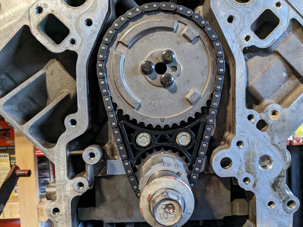
Once the rear was buttoned up, I spun it around to install the front side of the engine. I made sure to clean up the cam really well and glad that I did, because the hollow core of the cam had a lot of trash in it. Although they are brand new, it's a good idea to always clean up and inspect new parts. I followed up with the cam retainer, damper, and sprocket with new ARP bolts.
Next up was the oil pump. Now I've read mixed reviews on whether or not you need to center the oil pump on the crank, but given how easy it is to do, I feel like it's worth while. You basically install three shims around the drive which centers the housing and should make for a smoother operation. While I had it open, I put assembly lube on everything to hopefully help prime the engine faster/easier. Once the housing was torqued, I reinstalled the cover and torqued to 106 in/lbs.


While I had the engine off of the stand, I took the opportunity to clean up the 4L80e. Used more of the LA Awesome and some scrub brushes. Cleaned up very quickly, and I'll spray it quickly with some black or aluminum color. I want to let it dry for a few days.

Now here's where I hit a little snag. I have a dial indicator and figured it wouldn't take more than a few minutes to just check my cam end play. It seemed tighter than the other engines that I've assembled. When I got it set up and measured, it was measuring a .002" and then when I did a final torque on the cam bolts, it tightened up to .001". After a making a few calls to some buddies, I determined that it was too tight. I pulled the new cam retainer plate off and it was actually .003" thicker than the OEM piece that I removed. So given that the tolerances that I could find were .003" - .008", I think I found why it was too tight.
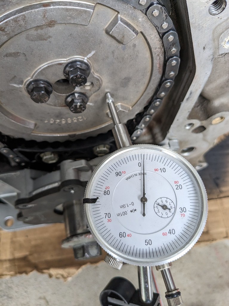
So for now I'm at a stand still. I need to reach out to Summit and see what they will do for me. I feel that the parts are not the right tolerance, so something needs to be addressed. If I were to run the engine as is, I feel that it will "self-clearance" and cause me a lot of issues.
Hopefully I'll have an answer by the end of the week and can get the motor/trans bolted together and re-installed.
Cheers,
Ryan


I really like the way that it's fitting, but I think that it needs to be tilted up slightly. I'm not sure if I'll attempt to make my own brackets, or modify the ones that I have. I need to think on it more. Great news it that it lines up with the brake pedal perfectly!

As I usually do, I was checking FB marketplace and found a guy giving away a DFP delete pipe for a 2011 F250. I know that I wanted a 4" pipe for when I swap on the turbo, so this will work perfectly. It's 409 SS so it does have some slight surface rust, but I should be able to clean that up. Now I'll keep an eye out for a turbo log manifold and downpipe. If I can score a deal on them in the next month or so, I'll make turbo placeholder pipe and plumb it all together. That way when I'm ready I'll just swap out the "fake turbo" for a real one haha. No point in spending money for a full dual exhaust when I'll be replacing it in the short term.

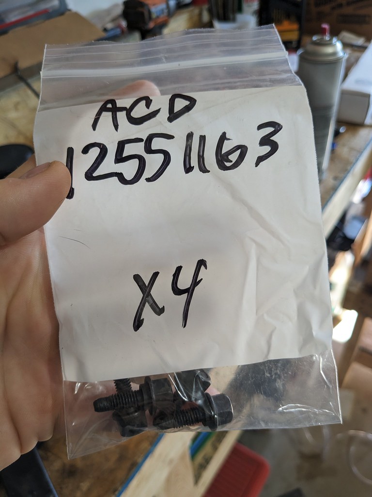
I received the last bolts that I needed to assemble the engine, so I got back on that. Head bolts and lifter retainer bolts. Got a deal on a set of once torqued ARP head bolts from an engine that was disassembled before it ran.


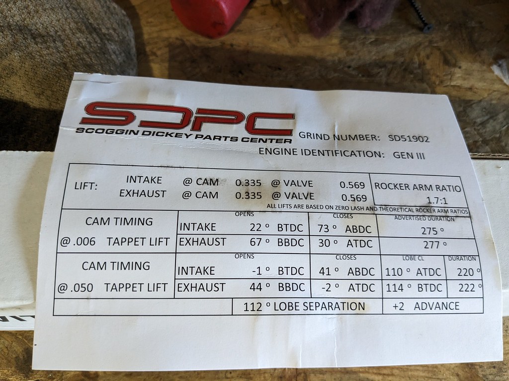
My plan all along has been to put this engine together on a fairly tight budget, and I had been planning to install a stock LS1 cam that I picked up from a buddy. In the end I just couldn't do it. I started looking for some low lift cams and stumbled on the SDPC LS6 Powermax PLUS Cam. It works perfectly with the LS3 springs I have as it's a fairly low lift cam at .570" . It's a 220/222 on a 112 LSA. While this cam won't make the most HP out there, it was only $269 shipped and worked with springs that I already had. Should make a nice street cam.


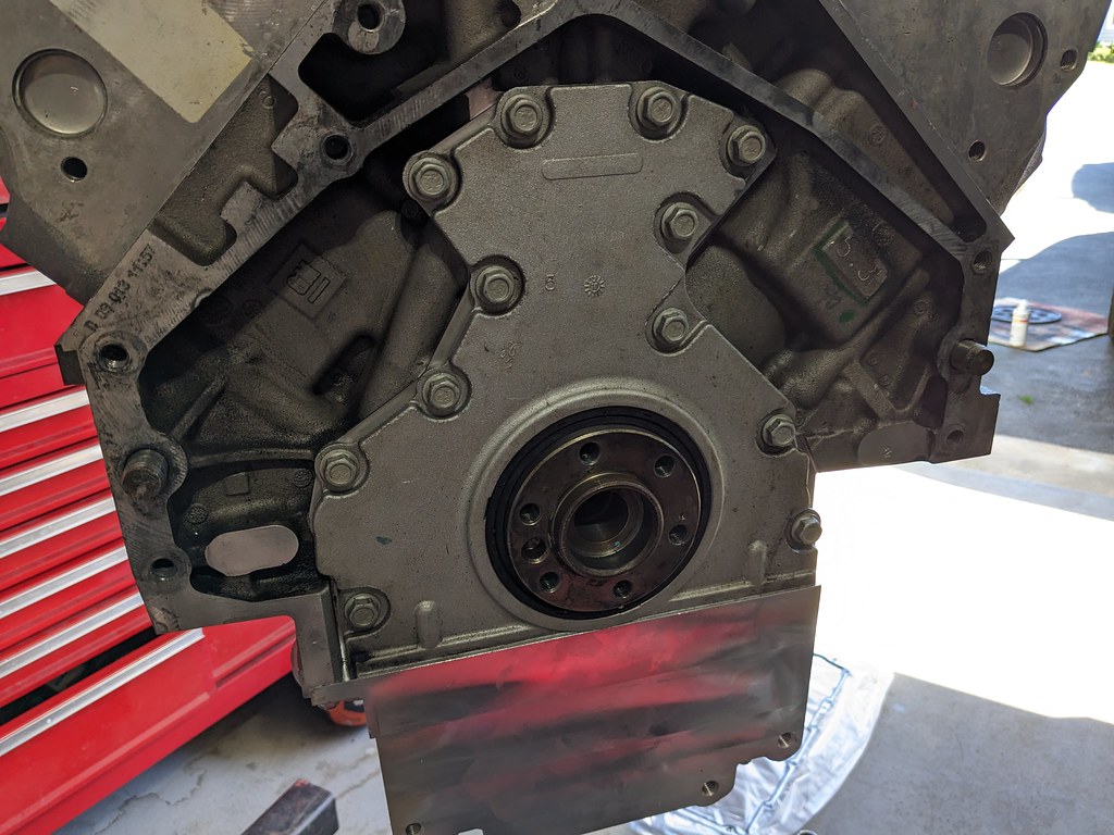
I started by installing the rear cover and gasket. I put a new main seal in and then got it centered on the crank. Once it was aligned, I torqued it all down and installed the flexplate. I'm using the 4L80e so I had to install a flexplate spacer with the appropriate ARP crank bolts. I had to get the engine off of the stand to get everything torqued, so I had my assistant give me a hand.


Once the rear was buttoned up, I spun it around to install the front side of the engine. I made sure to clean up the cam really well and glad that I did, because the hollow core of the cam had a lot of trash in it. Although they are brand new, it's a good idea to always clean up and inspect new parts. I followed up with the cam retainer, damper, and sprocket with new ARP bolts.

Next up was the oil pump. Now I've read mixed reviews on whether or not you need to center the oil pump on the crank, but given how easy it is to do, I feel like it's worth while. You basically install three shims around the drive which centers the housing and should make for a smoother operation. While I had it open, I put assembly lube on everything to hopefully help prime the engine faster/easier. Once the housing was torqued, I reinstalled the cover and torqued to 106 in/lbs.


While I had the engine off of the stand, I took the opportunity to clean up the 4L80e. Used more of the LA Awesome and some scrub brushes. Cleaned up very quickly, and I'll spray it quickly with some black or aluminum color. I want to let it dry for a few days.

Now here's where I hit a little snag. I have a dial indicator and figured it wouldn't take more than a few minutes to just check my cam end play. It seemed tighter than the other engines that I've assembled. When I got it set up and measured, it was measuring a .002" and then when I did a final torque on the cam bolts, it tightened up to .001". After a making a few calls to some buddies, I determined that it was too tight. I pulled the new cam retainer plate off and it was actually .003" thicker than the OEM piece that I removed. So given that the tolerances that I could find were .003" - .008", I think I found why it was too tight.

So for now I'm at a stand still. I need to reach out to Summit and see what they will do for me. I feel that the parts are not the right tolerance, so something needs to be addressed. If I were to run the engine as is, I feel that it will "self-clearance" and cause me a lot of issues.
Hopefully I'll have an answer by the end of the week and can get the motor/trans bolted together and re-installed.
Cheers,
Ryan
The following 2 users liked this post by ryeguy2006a:
patman2 (09-18-2023), Project GatTagO (09-27-2023)


