LS2 E40 Engine Control Module J1 Pin Assignments
#1
Teching In
Thread Starter
Join Date: Oct 2005
Location: Southern California
Posts: 20
Likes: 0
Received 0 Likes
on
0 Posts
I had been searching high and low for this information. 

2005 GTO LS2 E40 Engine Control Module Pin Assignments for the blue J1 Connector
Pin - Wire Color - Function
1 TN/BK High Speed GMLAN Serial Data Bus+
2 TN High Speed GMLAN Serial Data Bus-
3 Not Used
4 BN/WH Check Engine Indicator Lamp Output
5 Not Used
6 Not Used
7 BN Electronic Throttle Pedal Position Return 1
8 PU Electronic Throttle Pedal Position Return 2
9 Not Used
10 BN Engine Control Relay Coil Control
11 Not Used
12 Not Used
13 YE Starter Relay Output-Coil
14 PK Ignition 1 Voltage
15 Not Used
16 Not Used
17 Not Used
18 YE Accessory Voltage
19 OG Ignition 3 Voltage
20 OG/BK Battery Positive Voltage
21 PU/WH VSS Signal
22 BU Electronic Throttle Pedal Position Signal 1
23 Not Used
24 GN Fuel Tank Pressure Sensor Signal
25 Not Used
26 GN/BK A/C Refrigerant Pressure Sensor Signal
27 Not Used
28 Not Used
29* TN Electronic Throttle Pedal Position 5-Volt Reference 2
30 GN A/C Refrigerant Pressure Sensor Signal 5-Volt Reference
31 GY Fuel Tank Pressure Sensor 1, 5-Volt Reference
32 BU/RD Stop Lamp Switch Signal
33 Not Used
34 Not Used
35 WH/BK Electronic Throttle Pedal Position 5 Volt Reference 1
36 OG/BK Low Speed Cooling Fan Relay Control
37 PU Fuel Gage Sensor Signal
38 GY Extended Travel Brake Switch Signal
39 Not Used
40 Not Used
41 L-BU Electronic Throttle Pedal Position 2
42 YE Reverse Lockout Solenoid Control
43 PU/WH CPP Switch Signal
44 Not Used
45 GN/WH Fuel Pump Relay Feed-Coil
46 BN Cruise Control Release Signal
47 Not Used
48* BN/RD Tachometer Signal
49 Not Used
50 Not Used
51 GN/BU Park/Neutral Position Switch Park Signal
52 PU Crank Voltage
53 Not Used
54* WHT To BCM Connection 1 position 16
55 TN A/C Refrigerant Pressure Sensor Signal
56 BU/WH High Speed Cooling Fan Relay Control
* Denotes a difference from the Factory Service Manual (FSM).
29 FSM has the color listed as TH instead of TN.
48 FSM doesn't list the red stripe (BN/RD), only listed as solid brown (BN).
54 Is listed as Not Used. I split open the loom and followed it to the Body Control Module (BCM).
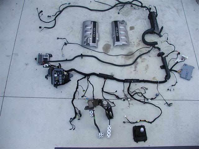
This thread was started to help myself and others pool together LS2 specific wiring information in one place. Now that HP Tuners alows us to use the LS2 with its E40 ECM I'd guess more guys will be using the LS2 pull outs.
Edited to add differances from FSM on pin 48.


2005 GTO LS2 E40 Engine Control Module Pin Assignments for the blue J1 Connector
Pin - Wire Color - Function
1 TN/BK High Speed GMLAN Serial Data Bus+
2 TN High Speed GMLAN Serial Data Bus-
3 Not Used
4 BN/WH Check Engine Indicator Lamp Output
5 Not Used
6 Not Used
7 BN Electronic Throttle Pedal Position Return 1
8 PU Electronic Throttle Pedal Position Return 2
9 Not Used
10 BN Engine Control Relay Coil Control
11 Not Used
12 Not Used
13 YE Starter Relay Output-Coil
14 PK Ignition 1 Voltage
15 Not Used
16 Not Used
17 Not Used
18 YE Accessory Voltage
19 OG Ignition 3 Voltage
20 OG/BK Battery Positive Voltage
21 PU/WH VSS Signal
22 BU Electronic Throttle Pedal Position Signal 1
23 Not Used
24 GN Fuel Tank Pressure Sensor Signal
25 Not Used
26 GN/BK A/C Refrigerant Pressure Sensor Signal
27 Not Used
28 Not Used
29* TN Electronic Throttle Pedal Position 5-Volt Reference 2
30 GN A/C Refrigerant Pressure Sensor Signal 5-Volt Reference
31 GY Fuel Tank Pressure Sensor 1, 5-Volt Reference
32 BU/RD Stop Lamp Switch Signal
33 Not Used
34 Not Used
35 WH/BK Electronic Throttle Pedal Position 5 Volt Reference 1
36 OG/BK Low Speed Cooling Fan Relay Control
37 PU Fuel Gage Sensor Signal
38 GY Extended Travel Brake Switch Signal
39 Not Used
40 Not Used
41 L-BU Electronic Throttle Pedal Position 2
42 YE Reverse Lockout Solenoid Control
43 PU/WH CPP Switch Signal
44 Not Used
45 GN/WH Fuel Pump Relay Feed-Coil
46 BN Cruise Control Release Signal
47 Not Used
48* BN/RD Tachometer Signal
49 Not Used
50 Not Used
51 GN/BU Park/Neutral Position Switch Park Signal
52 PU Crank Voltage
53 Not Used
54* WHT To BCM Connection 1 position 16
55 TN A/C Refrigerant Pressure Sensor Signal
56 BU/WH High Speed Cooling Fan Relay Control
* Denotes a difference from the Factory Service Manual (FSM).
29 FSM has the color listed as TH instead of TN.
48 FSM doesn't list the red stripe (BN/RD), only listed as solid brown (BN).
54 Is listed as Not Used. I split open the loom and followed it to the Body Control Module (BCM).
This thread was started to help myself and others pool together LS2 specific wiring information in one place. Now that HP Tuners alows us to use the LS2 with its E40 ECM I'd guess more guys will be using the LS2 pull outs.

Edited to add differances from FSM on pin 48.
Last edited by The Red Baron; 06-11-2006 at 04:13 PM.


