


here is a LS1 retrofit schematic
Thread Starter
On The Tree
Joined: Jul 2006
Posts: 167
Likes: 0
From: tx
ukv8, the 99 ls1 pdf file worked great for me.
Jhankinson, great job on the schematics. i had started on the 99-02 awhile back and never quite finished them.wish i had more "free time" like you do.
I'm thinking all of these schematics need to be moved into the sticky section...just so new guys ( like me ) can find them easier and use them.
chris p

On The Tree
Joined: Apr 2004
Posts: 166
Likes: 0
From: Oslo, Norway, Europe
om trying to write a pinout list on my 2004 gto LS1, ive found some badly scanned schematics im trying to work off, anyone seen any info on 2004 gto? i've got a book on it in the mail now.
Originally Posted by Davy_Baby9
This may be a stupid question but where the hell is the injector wires and coil wires?
I am wondering the same...? Am I just not seeing something?
Thread Starter
On The Tree
Joined: Jul 2006
Posts: 167
Likes: 0
From: tx
Originally Posted by JxxxOxxxE
I am wondering the same...? Am I just not seeing something?
The injector/coil wiring was not in the schematic simply because there is nothing different about it. It connects to the motor in the same manner as original. Basically, the schematic shows what wires/relays you will need to contend with for your swap.
ChrisP
LS1 Tech Stories
The Best V8 Stories One Small Block at Time

6 Common C5 Corvette Failures and What's Involved In Repairing Them
Pouria Savadkouei
Retro Modern Bandit Pontiac Trans AM Comes With Burt Reynolds' Autograph
Verdad Gallardo
Top 10 Greatest Cadillac V Series Performance Models Ever, Ranked
Pouria Savadkouei
Top 10 Most Powerful Chevy Trucks Ever Made!

Hennessey's New Supercharged Silverado ZR2 Has 700 HP
Verdad Gallardo
Coachbuilt N2A Anteros Is an LS2-Powered C6 Corvette In Italian Clothes
Verdad Gallardo
Awesome K5 Blazer Restomod Comes With C7 Corvette Power
Verdad Gallardo
10 Camaros You Should Never Buy

10 LS Engine Myths That Refuse to Die
Verdad Gallardo
Originally Posted by chrisp3
The injector/coil wiring was not in the schematic simply because there is nothing different about it. It connects to the motor in the same manner as original. Basically, the schematic shows what wires/relays you will need to contend with for your swap.
ChrisP
ChrisP
ok, but for some reason, I thought that you had to have seperate power supplies to the injectors and coils...?
Thread Starter
On The Tree
Joined: Jul 2006
Posts: 167
Likes: 0
From: tx
Originally Posted by JxxxOxxxE
ok, but for some reason, I thought that you had to have seperate power supplies to the injectors and coils...?
Wiring on separate circuits(as in the schematic) provides you with the factory type wiring, meaning you will have a 'limp home' mode if something were to happen to one side of coils/injectors. You would 'limp home' on half of the engine.
But if you wanted you could tie them all together and when/if there's a porblem you would be limping home via tow truck.


TECH Resident
Joined: Nov 2007
Posts: 816
Likes: 0
From: Texas
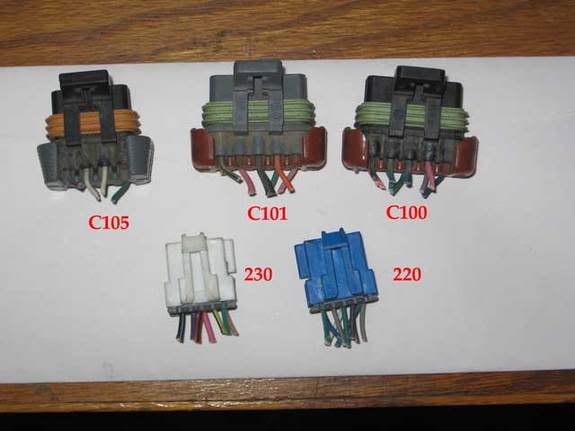
Guys the schematicis for the 99-up are already in the FAQ conversion thread in the stickys. It has already been done I used it on my swap. This picture will also help but I believe I discovered that the 220 and 230 are labeled wrong, they are swapped. If someone can confirm this I will edit the photo and correct it for all to use.

Teching In
Joined: Mar 2007
Posts: 39
Likes: 0
C100 pin A is hot in run and start IGN/INJ bank 1 15A
C101 pin B is hot in run and start IGN/INJ bank 2 15A
see this page for more info
http://www.dxsoftware.com/magnus/wiring.htm
Can someone explain how the A/C relay controlling C100 pins B(red 43 A/C clutch control) and pin C(red 18 A/C clutch status) relate to C230 pin F(red 17 A/C request signal)?
C101 pin B is hot in run and start IGN/INJ bank 2 15A
see this page for more info
http://www.dxsoftware.com/magnus/wiring.htm
Can someone explain how the A/C relay controlling C100 pins B(red 43 A/C clutch control) and pin C(red 18 A/C clutch status) relate to C230 pin F(red 17 A/C request signal)?
Last edited by TS99SS147; Apr 22, 2009 at 08:53 PM.

Teching In

Joined: Aug 2012
Posts: 9
Likes: 0
before someone was asking if this could be done for a 1999 harness. Well I had some free time so i figured i would write one up. If anyone sees anything wrong with it...just let me know so i can correct it ASAP.
J-
-edit-
I tried to include everything in the harness...A/C and all so for those who want it will have it as well.
J-
-edit-
I tried to include everything in the harness...A/C and all so for those who want it will have it as well.
