



Homemade VATS bypass box...

Thread Starter
TECH Fanatic
iTrader: (17)
Joined: Mar 2006
Posts: 1,746
Likes: 2
From: West Chester, PA
 Homemade VATS bypass box...
 Hey all. I have a handful of people asking me about the vats bypass box that I made...so I thought I would make a new post about it. I did a lot of searching, and it took me quite awhile to find info on it. Actually most of the info I found by using google not LS1tech. I realized that with LS1edit and HPTuners and maybe other software floating around, most people just get the VATS eliminated. I thought I did already but aparently not. So this is to help those people who are at the point where they want to run their car, but get stuck with vats.
This is a cheap project. Even if you dont have a soldering iron..radio shack has a good powered iron there for $7...cant beat that. Im going to post a couple sites that I found info on...then what I learned while building mine. I dont have any pictures of mine right now...but I can get them.
Here is the first site. This site contains the list of parts taht you will need. Write them down exactly as they are in the list...if you cant find the parts at radio shack...ask for help. They have them all.
http://temp.corvetteforum.net/c3/70lt1/vats.shtml
This site also references the site above..but provides a different configuration for how the parts are arranged. I wish I built mine like this...this makes it into a "security key" type thing. Im actually thinking about leaving the vats programmed in, and using it as an added security measure.
http://www.corvetteforum.net/c3/gameshowbob/swap6.html
Here is a link to the schematic for the box...just for quicker reference.
http://i57.photobucket.com/albums/g2...tschematic.jpg
The problem I had was when i put it together with the ground wire in the location shown, it didnt work. It did nothing. Car still acted the same. What I ended up doing is moving the ground wire to the pin on the 555timer that was for "ground". It shows you which pin that is on the back of the package. I cant remember which one it is right now...but I think its either 1 or 2... When I get home today Ill confirm it and update this post.
The box I made isnt pretty. I got the project box/circuit board combo from radio shack...so its bigger than the ones the other guys built. I only built it to make sure that was my problem. After I found out that it would run...I bought a box from baker electronics. Its small and I trust it alittle more as I built my box in a big hurry. But if you take you time, and make all your connections good, you can make it just as nice.
If you have any other questions feel free to ask... if you need help with soldering or building the circuit...shoot me a PM and Ill try to help you out.
Justin
This is a cheap project. Even if you dont have a soldering iron..radio shack has a good powered iron there for $7...cant beat that. Im going to post a couple sites that I found info on...then what I learned while building mine. I dont have any pictures of mine right now...but I can get them.
Here is the first site. This site contains the list of parts taht you will need. Write them down exactly as they are in the list...if you cant find the parts at radio shack...ask for help. They have them all.
http://temp.corvetteforum.net/c3/70lt1/vats.shtml
This site also references the site above..but provides a different configuration for how the parts are arranged. I wish I built mine like this...this makes it into a "security key" type thing. Im actually thinking about leaving the vats programmed in, and using it as an added security measure.
http://www.corvetteforum.net/c3/gameshowbob/swap6.html
Here is a link to the schematic for the box...just for quicker reference.
http://i57.photobucket.com/albums/g2...tschematic.jpg
The problem I had was when i put it together with the ground wire in the location shown, it didnt work. It did nothing. Car still acted the same. What I ended up doing is moving the ground wire to the pin on the 555timer that was for "ground". It shows you which pin that is on the back of the package. I cant remember which one it is right now...but I think its either 1 or 2... When I get home today Ill confirm it and update this post.
The box I made isnt pretty. I got the project box/circuit board combo from radio shack...so its bigger than the ones the other guys built. I only built it to make sure that was my problem. After I found out that it would run...I bought a box from baker electronics. Its small and I trust it alittle more as I built my box in a big hurry. But if you take you time, and make all your connections good, you can make it just as nice.
If you have any other questions feel free to ask... if you need help with soldering or building the circuit...shoot me a PM and Ill try to help you out.
Justin
Originally Posted by ghettocruiser
Here is the first site. This site contains the list of parts taht you will need. Write them down exactly as they are in the list...if you cant find the parts at radio shack...ask for help. They have them all.
http://temp.corvetteforum.net/c3/70lt1/vats.shtml
http://temp.corvetteforum.net/c3/70lt1/vats.shtml
Thread Starter
TECH Fanatic
iTrader: (17)
Joined: Mar 2006
Posts: 1,746
Likes: 2
From: West Chester, PA
70: I didnt know that was your site. Hope you dont mind me posting it up... It helped me about a lot. So you got the box to work with the ground wire positioned like the diagram shows??? Or did I miss something in my interpretation of the schematic?
Either way good work on that thing!!! Without that site I would have had to wait until getting back from florida to try to get it started. Do you know how much torture that would have been! Being down there and not knowing what was up with my car... haha.
Justin
Either way good work on that thing!!! Without that site I would have had to wait until getting back from florida to try to get it started. Do you know how much torture that would have been! Being down there and not knowing what was up with my car... haha.
Justin
Thanks for catching that, Justin. The description is wrong. Should read Pin 1 is ground, not pin 8. The schematic is drawn correctly.
Here is the correct description:
First you will need the following parts:
555 timer
a small pc board
3.3K resistor
2.2K resistor
10K resistor
100 Ohm resistor
two 0.1uF ceramic capacitors
1 uF electrolitic capacitor
12V Zener diode
small plastic enclosure
three pin connector
Connect one of the 0.1 uF capacitors between pins 1 and 8. Connect the 12V Zener diode between pins 1 and 8 with the banded (+) end to 8. This is to absorb voltage spikes caused by the starter. Also to pin 8 connect one end of the 100 Ohm resistor. The other end will be connected to an ignition hot source.
Connect pin 4 to 8 and pin 6 to 2.
Connect the 3.3K resistor between pins 7 and 8.
Connect the 2.2K resistor and the 10K resistor between pins 6 and 7 in series.
Connect the electrolitic 1uF capacitor + side to pin 6 and - side to pin 1.
Connect the other 0.1uF capacitor between pins 5 and 1.
Pin 1 is ground.
Pin 3 is output and can be connected to the PCM.
Here is the correct description:
First you will need the following parts:
555 timer
a small pc board
3.3K resistor
2.2K resistor
10K resistor
100 Ohm resistor
two 0.1uF ceramic capacitors
1 uF electrolitic capacitor
12V Zener diode
small plastic enclosure
three pin connector
Connect one of the 0.1 uF capacitors between pins 1 and 8. Connect the 12V Zener diode between pins 1 and 8 with the banded (+) end to 8. This is to absorb voltage spikes caused by the starter. Also to pin 8 connect one end of the 100 Ohm resistor. The other end will be connected to an ignition hot source.
Connect pin 4 to 8 and pin 6 to 2.
Connect the 3.3K resistor between pins 7 and 8.
Connect the 2.2K resistor and the 10K resistor between pins 6 and 7 in series.
Connect the electrolitic 1uF capacitor + side to pin 6 and - side to pin 1.
Connect the other 0.1uF capacitor between pins 5 and 1.
Pin 1 is ground.
Pin 3 is output and can be connected to the PCM.
Thread Starter
TECH Fanatic
iTrader: (17)
Joined: Mar 2006
Posts: 1,746
Likes: 2
From: West Chester, PA
70: Cool... This is a pic of the 555 timer schematic... Its kind of what I went off of when I got confused.

Im still going to double check mine when I get hom and see exactly where I put that ground wire... I mean...it has to be in the right spot or it wouldnt have worked.
I love building electronic stuff like that. I have no knowledge on designing it...but its fun to build it with a bunch of 99 cent parts that dont seem to do much. Then have it work and function...its a good sense of accomplishment.
Justin
Im still going to double check mine when I get hom and see exactly where I put that ground wire... I mean...it has to be in the right spot or it wouldnt have worked.
I love building electronic stuff like that. I have no knowledge on designing it...but its fun to build it with a bunch of 99 cent parts that dont seem to do much. Then have it work and function...its a good sense of accomplishment.
Justin
Thread Starter
TECH Fanatic
iTrader: (17)
Joined: Mar 2006
Posts: 1,746
Likes: 2
From: West Chester, PA
Sure... You could just add a switch to the power wire of the bypass box. Or to the ground or signal wire for that matter...
A few guys chose to make it accesable so they can just unplug the module and take it with them or hide it in the car. But a switch would be just as easy. With it unplugged or switched off the car will start and shut off right away.
Justin
A few guys chose to make it accesable so they can just unplug the module and take it with them or hide it in the car. But a switch would be just as easy. With it unplugged or switched off the car will start and shut off right away.
Justin
Trending Topics

Joined: Sep 2004
Posts: 3,148
Likes: 12
From: Downers Grove, IL
Originally Posted by 70 LS1
Cool, thats my site so if anyone has any questions, just ask. I have a bigger version of the schematic at home that is easier to read if anyone wants that as well.
 I didn`t realize that was your site either. I`ve had a link to it in my post in the FAQ sticky for a while now. Now there will be a link to this thread too
  .
.EDIT: I almost forgot to add, the VATS bypass box won`t work for truck,vette or GTO computers, they use a serial data signal which cannot be replicated. In these cars the VATS must be deleted in the computer. I didn`t want to see anyone with one of those computers build one and then have it not work
 .
.I have heard that you can make it work in the truck, vette, and GTO computers if you use a tuner to change the computer programming so that the computer is looking for the standard VATS signal. I cannot confirm this though since I don`t have any tuning software. I also don`t remember if it is HPTuners or EFILive7 or both that have the capability to change that parameter. Anyone else know?
Last edited by G-Body; Aug 30, 2006 at 09:28 PM.
LS1 Tech Stories
The Best V8 Stories One Small Block at Time

Gas Monkey Built a 6-Wheel Ferrari Testarossa With a Corvette LT4 Engine
Verdad Gallardo
7 Most Reliable High-Performance Engines GM Has Ever Built
Verdad Gallardo
Amazing '71 Camaro Restomod Is Modern Muscle Car Under the Skin
Verdad Gallardo
6 Common C5 Corvette Failures and What's Involved In Repairing Them
Pouria Savadkouei
Retro Modern Bandit Pontiac Trans AM Comes With Burt Reynolds' Autograph
Verdad Gallardo
Top 10 Greatest Cadillac V Series Performance Models Ever, Ranked
Pouria Savadkouei
Top 10 Most Powerful Chevy Trucks Ever Made!

Hennessey's New Supercharged Silverado ZR2 Has 700 HP
Verdad Gallardo
Coachbuilt N2A Anteros Is an LS2-Powered C6 Corvette In Italian Clothes
Verdad Gallardo
thanks, now i cant wait to build mine. mine ecu is already tuned for my motor, and i dont have access to any hp tuner stuff or any other software. im not quite ready to start mine yet but at least i know now i will be able to.
Thread Starter
TECH Fanatic
iTrader: (17)
Joined: Mar 2006
Posts: 1,746
Likes: 2
From: West Chester, PA
G-Body... Good point. I didnt think of putting in what vehicles this would work on.
Im still undecided on if I watn to get the VATS totally programmed out when I get the car tuned, or if I want to leave it in, and use the module as another security device. I already plan on a kill switch and an alarm. Might be overkill and just one more thing to go bad and leave me stranded... Chances are Ill leave it in long enough to do some good ing, then forget I even have it and it'll stay. haha.
Justin
Im still undecided on if I watn to get the VATS totally programmed out when I get the car tuned, or if I want to leave it in, and use the module as another security device. I already plan on a kill switch and an alarm. Might be overkill and just one more thing to go bad and leave me stranded... Chances are Ill leave it in long enough to do some good
ing, then forget I even have it and it'll stay. haha. Justin

Why exactly do you need to build a whole module? I just put a resister in between the 2 orange wires and it started right up. I havent had any problems. Is this what ya'll are talking about or is it something completly different. Sorry but I havent heard about this before.
I assume you are talking about your 2000 TA?
Here is the way VATS works. The BCM is connected to the ignition cylinder. When the correct resistance is sensed through the key, then the BCM will output a 5V 50Hz signal to the PCM. This allows the injectors to fire.
Most conversion guys don't use the BCM and must create this VATS signal and send it to the PCM.
I can only assume that in your case you found the correct value resistor to match your key and spliced it into the two wires coming from the BCM. Meaning your BCM is still creating the VATS signal to the PCM.
Here is the way VATS works. The BCM is connected to the ignition cylinder. When the correct resistance is sensed through the key, then the BCM will output a 5V 50Hz signal to the PCM. This allows the injectors to fire.
Most conversion guys don't use the BCM and must create this VATS signal and send it to the PCM.
I can only assume that in your case you found the correct value resistor to match your key and spliced it into the two wires coming from the BCM. Meaning your BCM is still creating the VATS signal to the PCM.
Thread Starter
TECH Fanatic
iTrader: (17)
Joined: Mar 2006
Posts: 1,746
Likes: 2
From: West Chester, PA
That works if you have the 4th gen f-body car and just want to bypass the resistor key. OR if you transferred all of the electronics from a 4th gen into another car...like the body control module and steering column..etc.
The box we are talking about is if you pull out the drive train from an LS1 car and are only using the PCM and harness. Nothing else. The PCM is looking for a signal from the body control module to tell it everything is ok security wise. This bypass box basically emulates that whole vats system and tells the PCM that the correct key is in the ignition and all other parameters are good to allow the engine to run.
Justin
Edit... Doh...70 beat me to it. I forgot to hit submit after I was done typing..
The box we are talking about is if you pull out the drive train from an LS1 car and are only using the PCM and harness. Nothing else. The PCM is looking for a signal from the body control module to tell it everything is ok security wise. This bypass box basically emulates that whole vats system and tells the PCM that the correct key is in the ignition and all other parameters are good to allow the engine to run.
Justin
Edit... Doh...70 beat me to it. I forgot to hit submit after I was done typing..

Thread Starter
TECH Fanatic
iTrader: (17)
Joined: Mar 2006
Posts: 1,746
Likes: 2
From: West Chester, PA
Paul... Not sure about your starting issue. Ive heard that the security light comes on if there are issues. But I wouldnt know. This info was more for drivetrains that were no longer in 4th gen bodies. The DIY stand alone harness guys. However...Im sure there is a way to check to see if you problem is VATS related or not. And just to clarify...most of the time your car will start even if VATS is acting up. But it will start up and shut off. If its a problem with the resistor in the key...I dont know that it will even crank. In that case, you could try bypassing the resistor with circuit resistors...there aer bunch of threads on how to do that.
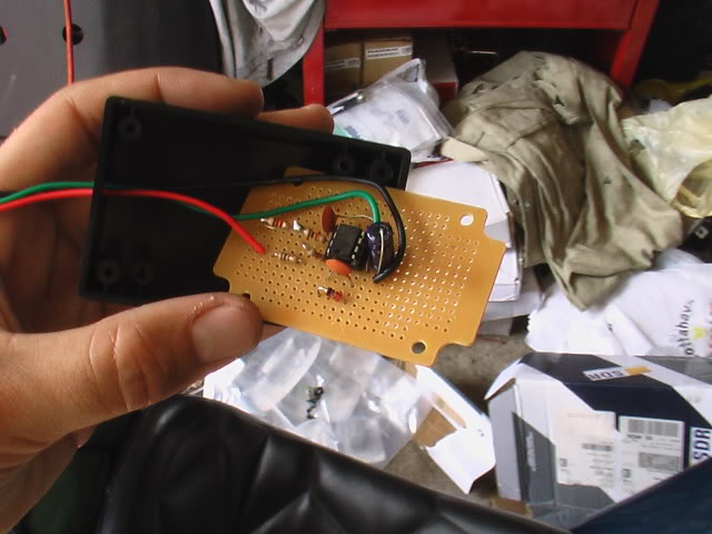
Just for fun here is a pic of my masterpiece...not! haha. I soldered this together in like 20 minutes so its not the best. But it proved my car would run, so it served its purpose.
Justin
Just for fun here is a pic of my masterpiece...not! haha. I soldered this together in like 20 minutes so its not the best. But it proved my car would run, so it served its purpose.
Justin

On The Tree
Joined: Apr 2005
Posts: 192
Likes: 0
From: S. Philly
Justin,
Where are you located? Any chance I can get you to build me one for my next project?
The VATs you guys been talking about is actually call "Pass-key". The VATs is what being controlled by the remote control (or key fob). Normally this is already disabled. In order to enable this you have to arm the alarm system by the remote control or using the key lock at the door. Without the BCM the VATs doesn't affect anything. The VATs usually refers to as Content Theft Deterent system.
The Pass-key is usually refers to as Vehicle Theft Deterent system. This is what actually prevent the car from stolen. The Pass-key requires inputs from the key-in ignition, the resistor on the key and the steering column lock. You can't just put in a resistor in to replace the key and expect it to work. The BCM needs to read 3 of these signal in the correct sequence in order for the BCM to send the fuel enable password to the PCM to enable the fuel.
This is based on the C5 manuals. Trust me I've been doing a lot of research on this topic so I know.
Where are you located? Any chance I can get you to build me one for my next project?
The VATs you guys been talking about is actually call "Pass-key". The VATs is what being controlled by the remote control (or key fob). Normally this is already disabled. In order to enable this you have to arm the alarm system by the remote control or using the key lock at the door. Without the BCM the VATs doesn't affect anything. The VATs usually refers to as Content Theft Deterent system.
The Pass-key is usually refers to as Vehicle Theft Deterent system. This is what actually prevent the car from stolen. The Pass-key requires inputs from the key-in ignition, the resistor on the key and the steering column lock. You can't just put in a resistor in to replace the key and expect it to work. The BCM needs to read 3 of these signal in the correct sequence in order for the BCM to send the fuel enable password to the PCM to enable the fuel.
This is based on the C5 manuals. Trust me I've been doing a lot of research on this topic so I know.
Thread Starter
TECH Fanatic
iTrader: (17)
Joined: Mar 2006
Posts: 1,746
Likes: 2
From: West Chester, PA
Hey man... How are things going?? Well...Ill tell you what. If you can hold out for a little bit, so I can make sure I wont need it, Ill sell you this one really cheap. Basically to cover some of the parts. Im about an hour from philly...but like I said, Im in the langhorn area often. I need to finish up alittle bit of work on the car, and see if it will fire and run... if it does...Ill have no need for this box. I can either ship it to ya or we can meet up next time Im out that way. Maybe I can stop by and check out your project??
Justin
Justin

On The Tree
Joined: Apr 2005
Posts: 192
Likes: 0
From: S. Philly
Justin,
Everything is OK. I put my project aside since last week when I got it running. Now I am working my friend's 280Z and I will be putting in a 2001 Camaro drivetrain. Just got done cleaning up his engine bay. Hopefully I will finish painting the bay tomorrow. Then the motor will go in Sat.
I was kinda joking around when I asked you build one for me. Now I see the picture it probably won't take me long to build it. I am an electrial engineer and electronics is my background BTW lol. I will probably sending the PCM to Jesse tomorrow to disable the "VATs" and other unused stuffs. If you happen to be around Philly give me a call and we will meet up. You are welcome to come and check out my junks hehe.
Thanks for the offer.
Vinh
Everything is OK. I put my project aside since last week when I got it running. Now I am working my friend's 280Z and I will be putting in a 2001 Camaro drivetrain. Just got done cleaning up his engine bay. Hopefully I will finish painting the bay tomorrow. Then the motor will go in Sat.
I was kinda joking around when I asked you build one for me. Now I see the picture it probably won't take me long to build it. I am an electrial engineer and electronics is my background BTW lol. I will probably sending the PCM to Jesse tomorrow to disable the "VATs" and other unused stuffs. If you happen to be around Philly give me a call and we will meet up. You are welcome to come and check out my junks hehe.
Thanks for the offer.
Vinh

Registered User
Joined: Feb 2008
Posts: 2
Likes: 0
70: I didnt know that was your site. Hope you dont mind me posting it up... It helped me about a lot. So you got the box to work with the ground wire positioned like the diagram shows??? Or did I miss something in my interpretation of the schematic?
Either way good work on that thing!!! Without that site I would have had to wait until getting back from florida to try to get it started. Do you know how much torture that would have been! Being down there and not knowing what was up with my car... haha.
Justin
Either way good work on that thing!!! Without that site I would have had to wait until getting back from florida to try to get it started. Do you know how much torture that would have been! Being down there and not knowing what was up with my car... haha.
Justin
Connect the electrolitic 1uF capacitor + side to pin 6 and - side to pin 1.
Should be Connect the electrolitic 1uF capacitor + side to pin 2 and - side to pin 1.
I just found another goof in the text, but the schematic is correct. Thanks for sharing this, it saved me a ton of money and time!
Connect the electrolitic 1uF capacitor + side to pin 6 and - side to pin 1.
Should be Connect the electrolitic 1uF capacitor + side to pin 2 and - side to pin 1.
Connect the electrolitic 1uF capacitor + side to pin 6 and - side to pin 1.
Should be Connect the electrolitic 1uF capacitor + side to pin 2 and - side to pin 1.