When you click on links to various merchants on this site and make a purchase, this can result in this site earning a commission. Affiliate programs and affiliations include, but are not limited to, the eBay Partner Network.
I realized that there was only so much vertical room I'd have for moving the inner tie rod end up as on the passenger side it would hit my turbo oil drain line into the oil pan, if I moved the inner TRE up the approx. 2" that the Ridetech TruTurn kit does. I also discovered that I had the manual steering slow ratio 6.0" long steering arms. Not only would using the Gbody steering arms (to copy TruTurn) require moving the inner TRE up too much, I measured the steering arms at around 5.5" long.. so I decided to search for quick ratio power steering Fbody arms. I found a set on eBay, they are 5.18" long so will give me the quickest turning, but still retain 3" drop in order to keep the amount the inner TRE has to go up to a reasonable amount. The short 5.18" length is also enough to tuck the outer TRE inside the rim hoop with about 3/8"" radial clearance
Starting fiddling with moving inner tie rod end upwards to see approx how much it would need to be raised to improve bumpsteer.. first guess was 5/8" (16mm) and it got close but overshot a bit and got toe in under compression. I then reduced the relocation to 9/16" (14mm) above stock location and got the total toe change to 0.078" total toe out under 2.5" compression.
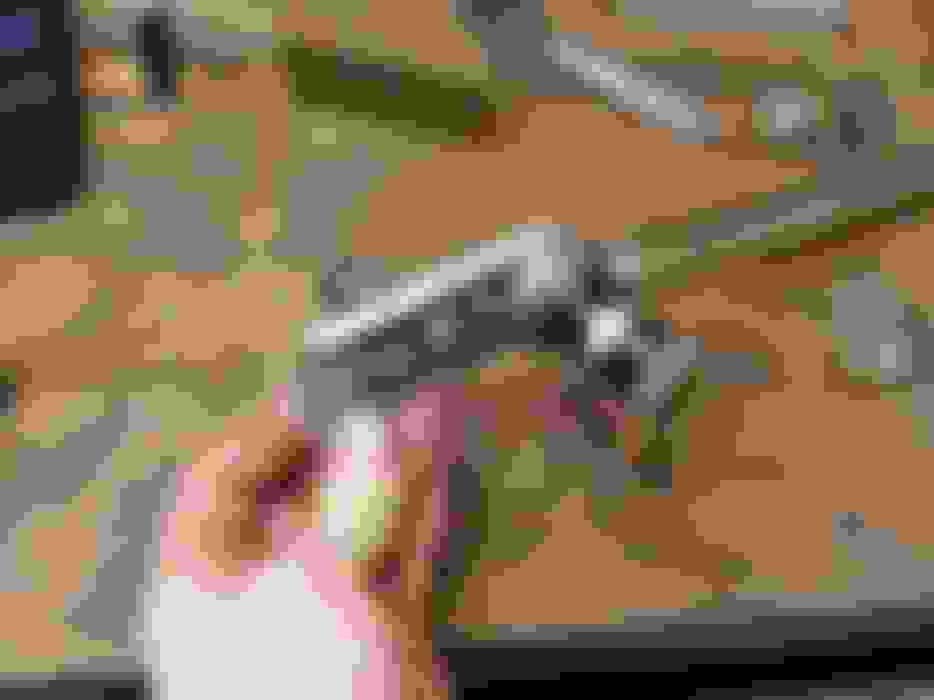
Check the pics for how I was moving the inner TRE around. 5/8" bolt thru a heim (only for experiments) into an aluminum block, then smaller 5/16" bolt that goes thru the drag link. I intentionally used a smaller bolt thru the tapered hole in the drag link to give me a couple millimeters of adjustment room for fiddling. On the other end of the aluminum block I'm going to drill the 5/16" hole at 15mm vertical offset to split the difference of the above two experiments, but also drill the hole laterally offset in the block so I can flip the block and start testing the affect of changing the length of the steering link (moving inner TRE laterally inboard and outboard).
Bumpsteer investigation, round 2.. for testing purposes I pegged the inner TRE raise amount at 15mm, and shifted the inner TRE inboard & outboard offset distances at 20mm and 40mm relative to factory horizontal hole location on the drag link.
Interestingly, moving the inner TRE inboard 40mm makes the curve almost linear, meaning I've almost matched the sweeping arc of the steering link compared to the virtual pivot point of the UCA/LCA linkage, over the 5" travel range. Now that the path of the steering arm is more consistant due to a matched arc of the steering arm, in order to minimize the steering input that near-linear line needs to be brought as close to vertical as possible, so I'll try lowering the inner TRE from 15mm raised height and see what happens.
HAH. I may be a sucker for researching things, but I can tell pretty quickly what wouldn't make a good project.. I'll leave my minimal understanding as it is since it seems to be getting me by just fine.
this is some really good stuff, but help me understand your charts. you're putting the toe and camber on the x-axis...? and the y-axis is shock travel, with up being compression...?
I'm also confused with the camber gain chart. A stock camaro/nova should gain positive camber under compression. a RideTech setup, on the other hand, gains negative camber under compression. So I think your and the Pozzi lines should be mirrored along the y-axis.
You're correct.. y-axis is suspension bump (positive) or droop (negative).. just because that's how my brain works. Toe (measured total, AKA the bumpsteer measurement doubled) is positive as the car toes out, and negative as car toes in. Camber is self explanatory for positive & negative.
Very true, traditionally the 1st gen suspension should camber positive in stock form under bump, however according to Ridetech's website, a stock suspension with only Ridetech arms will camber negatively (even though only slightly) under bump. However this could be with lowering springs to slam the front end enough such that at the starting ride height, the control arm geometry has already crested over the positive camber point and will start to negative camber under bump.
For Pozzi's measurements.. good catch. I went back and re-checked and looks like I copied the values reversed. I can't seem to find the actual text list of camber/travel numbers that I copy-pasted into Excel, however he clearly explains on his page that up/positive is droop and down/negative is bump... however he still lists negative camber gain under bump. The starting point (ride height) appears to be very important for camber gain, especially with taller spindles or Gulstrand mod as those affect the "sensitivity" of camber gain from said ride height starting point.
For mine, I have done the Gulstrand mod, as well as mine being super low, so my instant center is quite lower on the car making it negative camber pretty aggressively with not too much bump.
I completely forgot that you had done the guldstrand mod + ridetech arms! I eventually got it all sorted, I just had to rearrange things in my head. I've been deliberately not working on mine, and just enjoying driving her; now you're making me want to start wrenching on her again.
I was the same with mine from ~April until it just got consistently rainy ~November, but the bumpsteer is something I really needed to investigate/address. Plus I really wanted 14" rotors and 275's on the front hehe.
Don't worry, that'll be a good distraction.. for a while.....
I haven't touched my XS500 since 2 Novembers ago.. for some really silly reason like car being driveable anytime I wanted and glorious boost, etc. But I really need to bob the seat/taillight section of the moto and get it running again to commute to work on it this summer.
I'm doing a full-on cafe build, so it'll be a distraction for a couple months, at least (though it's now rideable, and super easy to work on, so that might be too long a timeframe). I just got it running, but it's far from public roadworthy (no mufflers, no front brake, exposed wiring, poor tune, etc. etc.).
Last edited by hookemdevils22; Feb 26, 2016 at 11:33 AM.
Did some more on the steering today. In my last update post I stated that I had found a new lateral location for the inner tie rod end, to make the bumpsteer curve pretty damn linear. So I continued on that today with finding a new height at the more-inboard location, to get a linear and vertical bumpersteer curve. I kinda lucked out and randomly moved the tie rod end down 1/8" and got it right the first try.
Below is the bumpsteer curve for rev10.. one line shows it at 0* steering angle, and another shows it at 10* steering angle. So when the car dives at 10* steering angle, the front tires toe in, and when the car lifts, the tires toe out. This required me to take bumpsteer measurements with reference wheel (passenger side for my measuring setup) turned 10* outboard, then again at 10* inboard, and use the addition of the two for calculating travel bumpsteer when the wheels are turned. This is assuming no body roll, which of course is not exactly accurate to real life even with the stiffest front sway bar..
Because the body rolls during cornering, I also calculated the toe-out curve for 10* steering angle, as the body rolls thru the wheel travel..
Using the toe-vs-travel, and toe-vs-roll, I could technically figure out what the bumpsteer/toe gain could be for a particular cornering situation of say 1.5* body roll and 0.5-1" dive from braking, blah blah blah, but that isn't necessary now and the beer is making me not care as much.
I also got the new caliper brackets made to fit the lug-mount Wilwood Superlite 6 piston calipers onto the larger 14" rotors. You may as "why the f*** would he make brackets and not buy them?".. well the 14" rotor version of my kit was only ever offered as a radial-mount setup for a 14" rotor, even tho the caliper looks otherwise identical to mine. So since I couldn't use the official Wilwood 14" brackets without getting new calipers as well, I made.
Some stats: Previous Wilwood 13" brackets were 3/8" thick, mine are 1/2" thick. Previous had significant profile cutting, mine have more beef and less weight-saving cutting. Previous were surprisingly made of 6061-T6 aluminum (don't believe the "aerospace spec technology".. this stuff is as standard as it gets and not the strongest around) at ~45,000psi ultimate strength. Mild steel is ~63,000psi ultimate tensile strength. I made my brackets out of 7075-T651 aluminum.. 83,000psi ultimate tensile strength! Enough blabbing...
Got around to modifying the center link for new optimized inner tie rod end positions. I 3D modelled several different designs but ultimately came up with turned location slugs partially recessed into a notched center link, with gusseting for over-building the strength.
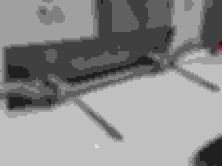
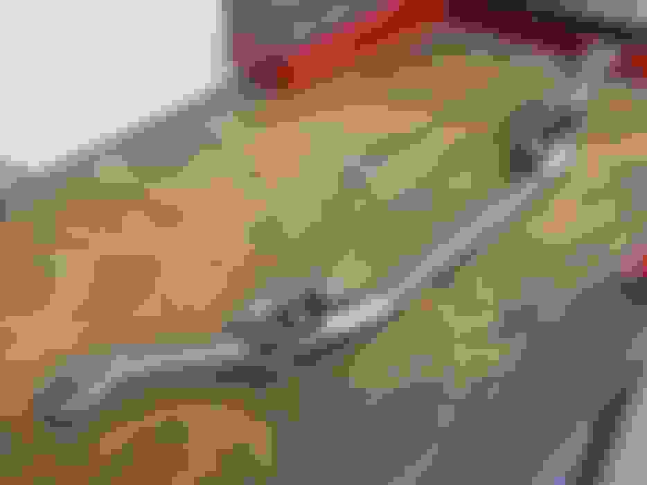
Started with clearance cutting the center link..
Then used an adjustable boring bar to bring the notch diameter up to the OD of the slugs for the new inner tie rod end tapered holes�
Of course the proper way to do all of this for fitment checking as well as welding is to have a jig to hold it all together�
Did 3 passes of the slugs themselves (center link was heavily chamfered previous to welding, to ensure good penetration�
Then cut out and added gussets for even more strength�
First weld pass on gussets�
The final (4th or 5th pass, can�t remember) weld pass�
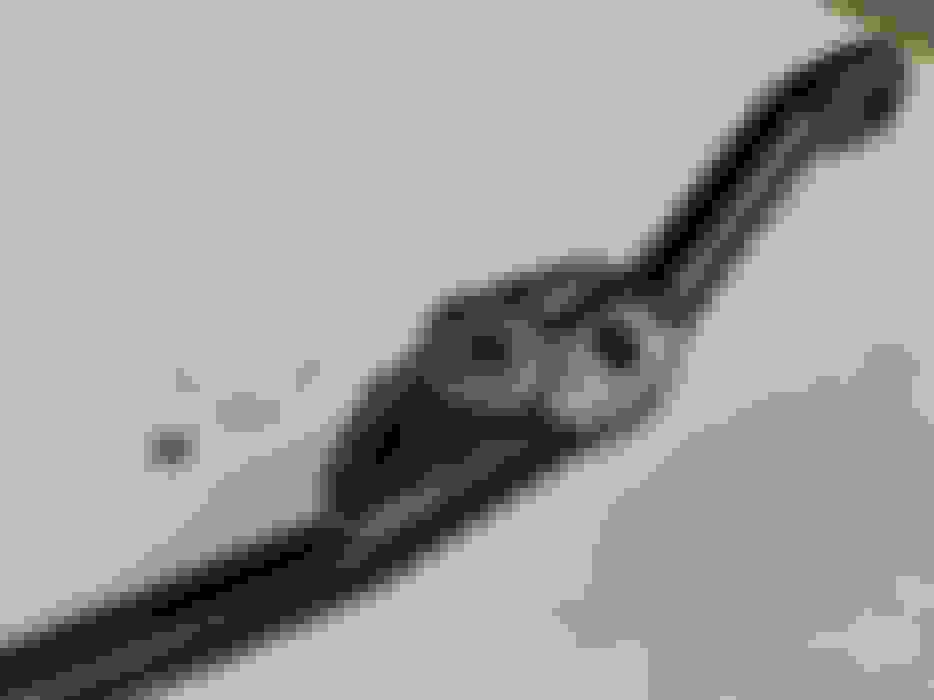
Ground the gussets down a bit to streamline them and painted. Still need to ream the tapers into the new locations and clean up the tapers on the existing holes for pitman and idler arms..
I was using the Dynasty 350 at work set at about 215 amps, the pedal was about 40-50% most of the time with startup using maybe 75%, and went thru about 20ft of filler rod. Used a gas lense (forget the cup size) with a 1/8" thoriated electrode with decent stick-out and 1/16" filler. Welded like BUTTER.. I dunno the origin of the center link steel but it was shockingly high quality with zero impurities or porosity.
Gas Monkey Built a 6-Wheel Ferrari Testarossa With a Corvette LT4 Engine
Slideshow: The controversial Ferrari F6 swaps its original flat-12 for a Corvette Z06-derived LT4 V8 and sends power to four rear wheels through a custom-built drivetrain.
7 Most Reliable High-Performance Engines GM Has Ever Built
Slideshow:These GM engines didn't just make huge power, they survived abuse, boost, track days, and six-digit mileage with a reputation for refusing to quit.
6 Common C5 Corvette Failures and What's Involved In Repairing Them
Slideshow: From wobbling harmonic balancers to failed EBCMs, these are the issues that define long-term C5 ownership and what repairs typically involve.
Retro Modern Bandit Pontiac Trans AM Comes With Burt Reynolds' Autograph
Slideshow: A modern Camaro transformed into a retro icon, this limited-run "Bandit" build blends nostalgia with brute force in a way few revivals manage.
Top 10 Greatest Cadillac V Series Performance Models Ever, Ranked
Slideshow: Cadillac didn't just crash the high-performance luxury vehicle party, it showed up loud, supercharged, and occasionally a little unhinged...