
Taking the plunge: LS3 into '64 Tempest. Need help with shopping list.
 05-16-2009, 11:35 PM
#101
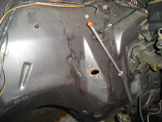
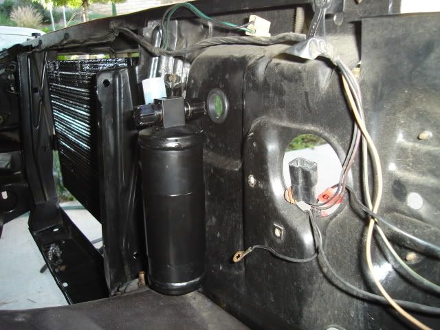
.....in preparation for the A/C install. The inner fender on the passenger side needed to come out so the old heater box assembly on the firewall could be removed.
The front bumper needed to come off first, it would have to be removed to do the body mount replacement anyway. The grilles were removed as well to have access to the core support so I can mount the condensor.
There are also two 1-1/4" holes that need to be cut so the A/C hoses can pass through the support to the condensor.
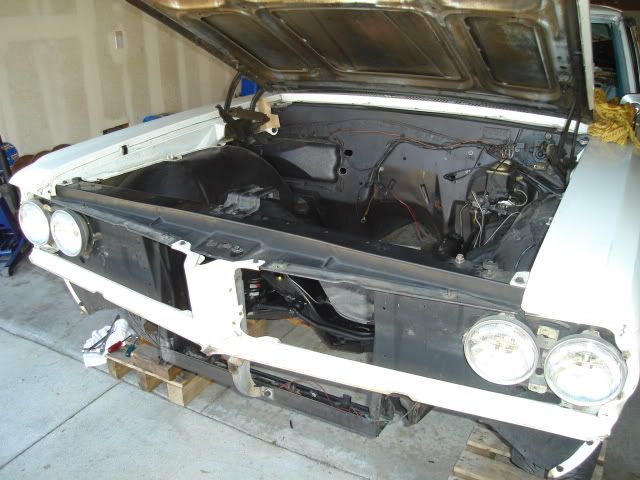
I took off the fender, even though the A/C kit instructions show it staying in place. It's easy to scratch up the paint on both the frame and inner fender trying to get it out with the fender in place.
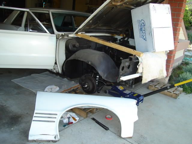
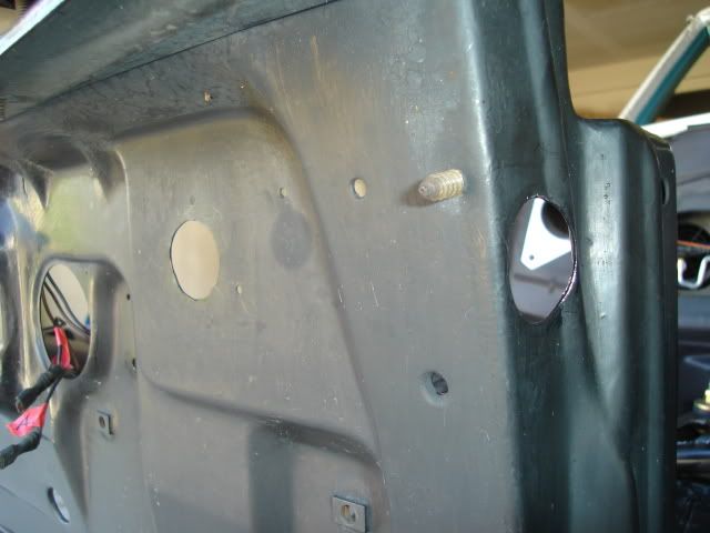
The heater box assembly came off easily by removing the last two screws that were still holding it to the firewall right next to the fan motor. The six nuts holding the rest of it down had already been removed while I was taking out the inner heater box under the dash.
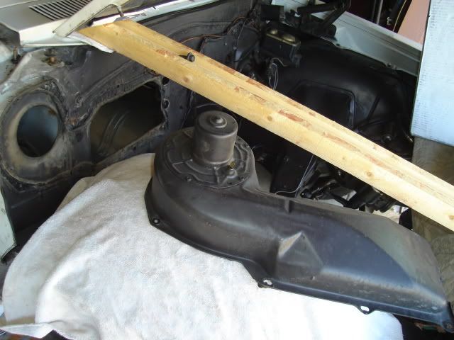
I used a putty knife to remove most of the factory sealer, the temps were in the 90s here today so the sealer was pretty soft. The remaining sealer residue came off easily using some old gasoline that I drained from the old Tempest fuel tank.
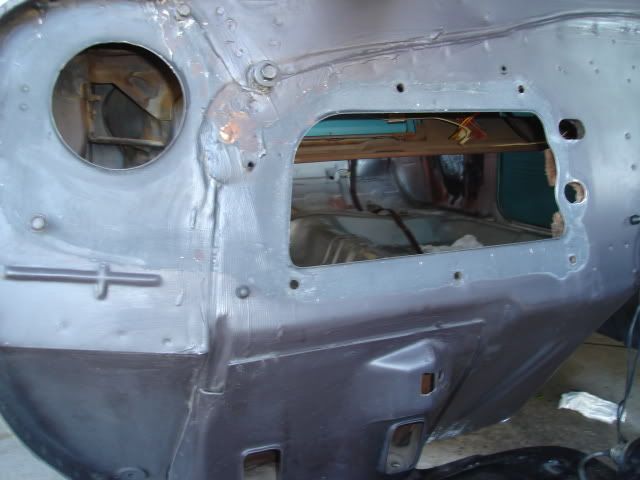
Here's the main blockoff plate that was supplied in the kit being held in place.
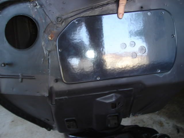
Rather than use the supplied blockoff plate for the heater blower opening I'll use this 4" hose adapter that I fabbed out of stainless steel. This way I can supply the LS3 intake with some cool air ducted from the cowl vents.
The hose adapter is a piece I removed from my '64 GTO when I retired it from the dragstrip and put the stock heater assembly back in.
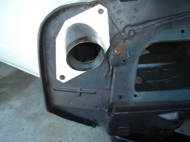
I scrounged this factory intake hose and several others like it from a self-serve boneyard about 15 years ago when the mid-70s GM cars could still be commonly found there.
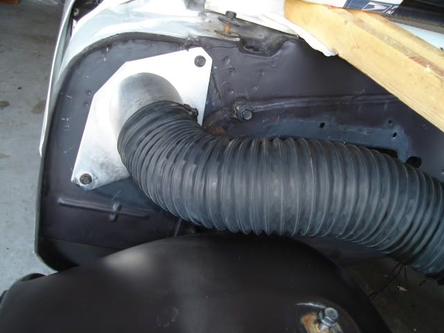
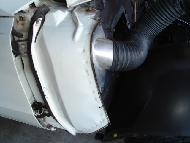
Another view of the hose adapter and intake hose. I took the opportunity to tidy up the original white paint on the cowl with a little Simple Green. Did I say this thing was cherry?
Heres a pic of the 455 HO engine in my GTO with the cool intake air from the cowl taken from two locations. The hose on the driver's side connects to another adapter that takes the place of the factory wiper motor, another thing I removed to save weight at the time.
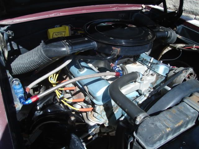
I'm looking at doing something similar with the LS3 but with only one inlet. I'm going to see if I can mount a stock '73 -'74 Pontiac V8 aircleaner on top of the engine just like the one pictured above.
Hopefully there's going to be room to build a big enough intake plenum over the stock LS3 intake to mount the air cleaner on and still get the airflow needed. No matter what I'll find a way to duct cool air from my fitting at the heater blower opening to some sort of air filter.
Still goin' at it.
The front bumper needed to come off first, it would have to be removed to do the body mount replacement anyway. The grilles were removed as well to have access to the core support so I can mount the condensor.
There are also two 1-1/4" holes that need to be cut so the A/C hoses can pass through the support to the condensor.
I took off the fender, even though the A/C kit instructions show it staying in place. It's easy to scratch up the paint on both the frame and inner fender trying to get it out with the fender in place.
The heater box assembly came off easily by removing the last two screws that were still holding it to the firewall right next to the fan motor. The six nuts holding the rest of it down had already been removed while I was taking out the inner heater box under the dash.
I used a putty knife to remove most of the factory sealer, the temps were in the 90s here today so the sealer was pretty soft. The remaining sealer residue came off easily using some old gasoline that I drained from the old Tempest fuel tank.
Here's the main blockoff plate that was supplied in the kit being held in place.
Rather than use the supplied blockoff plate for the heater blower opening I'll use this 4" hose adapter that I fabbed out of stainless steel. This way I can supply the LS3 intake with some cool air ducted from the cowl vents.
The hose adapter is a piece I removed from my '64 GTO when I retired it from the dragstrip and put the stock heater assembly back in.
I scrounged this factory intake hose and several others like it from a self-serve boneyard about 15 years ago when the mid-70s GM cars could still be commonly found there.
Another view of the hose adapter and intake hose. I took the opportunity to tidy up the original white paint on the cowl with a little Simple Green. Did I say this thing was cherry?
Heres a pic of the 455 HO engine in my GTO with the cool intake air from the cowl taken from two locations. The hose on the driver's side connects to another adapter that takes the place of the factory wiper motor, another thing I removed to save weight at the time.
I'm looking at doing something similar with the LS3 but with only one inlet. I'm going to see if I can mount a stock '73 -'74 Pontiac V8 aircleaner on top of the engine just like the one pictured above.
Hopefully there's going to be room to build a big enough intake plenum over the stock LS3 intake to mount the air cleaner on and still get the airflow needed. No matter what I'll find a way to duct cool air from my fitting at the heater blower opening to some sort of air filter.
Still goin' at it.
 05-24-2009, 01:07 AM
#102
.....were two important tasks I took on and completed today.
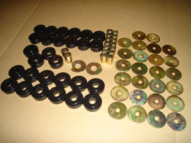
New Energy Suspension polyurethane body mounts. I used a pair of new reproduction core support mounts made of rubber, poly mounts were not available for those.
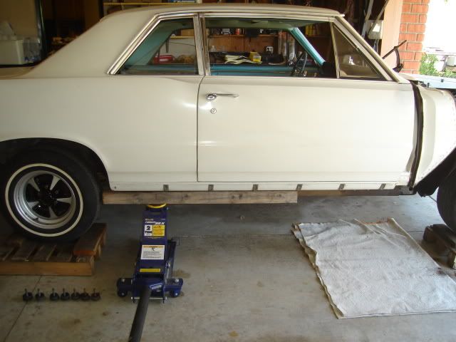
I jacked up the passenger side of the Tempest body first after removing all the bolts on that side and loosening all of the bolts on the other side. The front of the body still came up before the rear even with the jacking point this far back.
Old mount at the rear of the car.
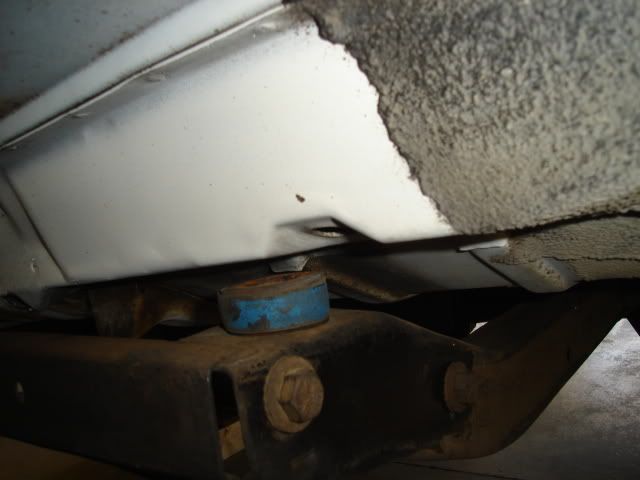
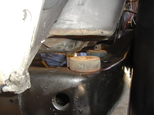
Two old mounts at the front below the firewall. The car doesn't need to come quite this far off the frame to remove them.
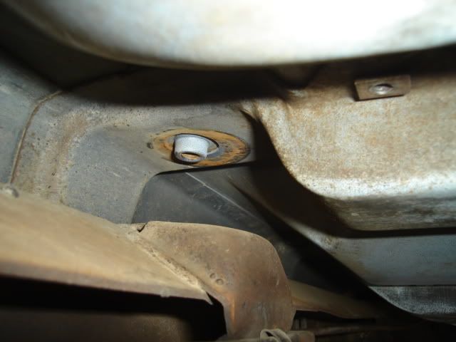
A look at the center frame mount area with the old mount removed, right next to the seat belt mounting point.
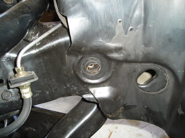
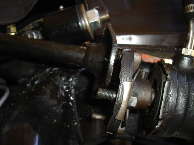
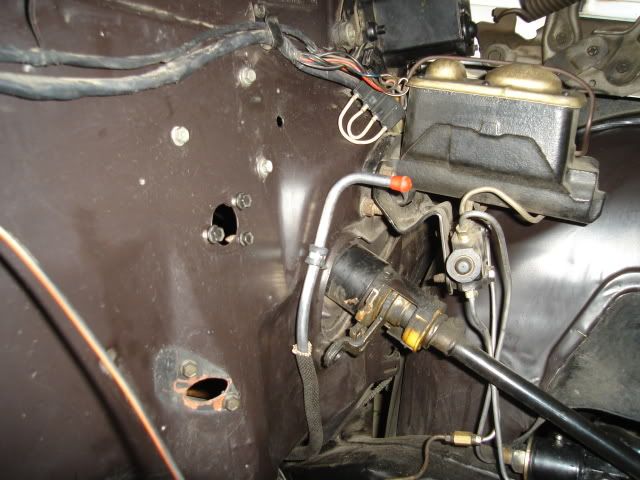
The bolt holding the front inner fender to the frame needs to come out on both sides (driver's side shown), this important step is not mentioned in the body mount installation instruction sheet. I took the brake hose bracket loose from the frame as well.
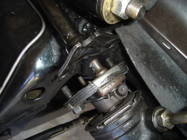
The steering column needs to be taken loose at the rag joint and loosened under the dash so you can pull it back about 1" or a little less. Another important thing that is not mentioned in the instructions.
Old mounts removed, in pretty sorry shape. The rearmost ones (seen at the left) were compressed less than the ones closer to the center and front of the car. The original body bolts were in good shape and after some work with a wire brush they were reused after coating the threads with copper anti-seize compound.
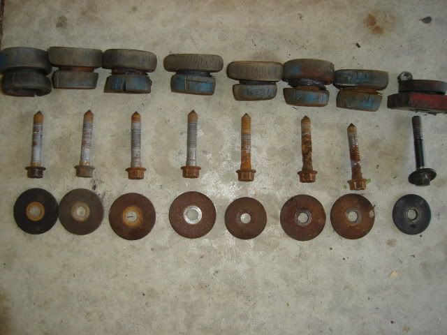
New reproduction 3/8" steel fuel line from Performance Years. They all come with a soft bend in the middle for shipment that's easily straightened out before installation.
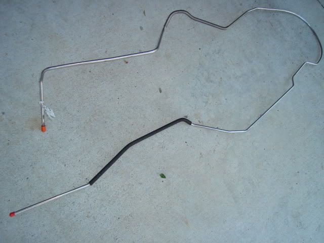
All straight and ready for installation. The 1964 -'67 A-body cars came with 5/16" line from the factory and that is the size you'll see in the PY catalog. Just ask them and they will do it in 3/8" for you by special order.
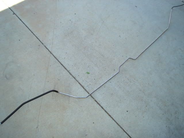
After finishing the passenger side mount installation and leaving the bolts loose I jacked up the driver's side. I jacked up the body a few more inches so I could snake the new fuel line into place. After looking things over I decided that feeding the line through the rear wheel well opening would work without having to bend up the line.
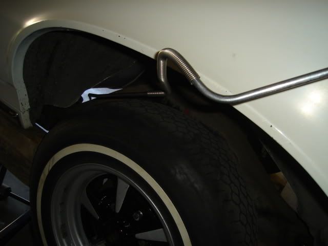
Feeding it in.
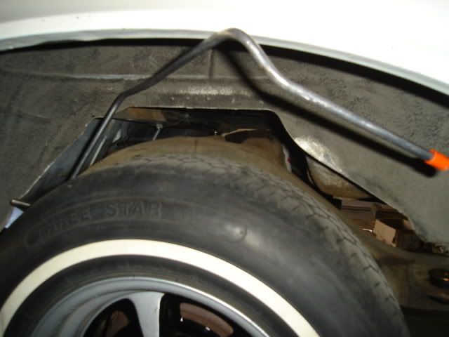
This shot gives you an idea of where it has to go near the rear.
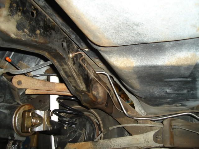
Here you can see it running towards the front of the car. The 3/8" line clips right into the three 5/16" factory clips on the frame making for a neat and easy installation.
Rather than run the line through the front frame rail and out the front crossmember like the factory would have I bent the line so it would hug the firewall and head upward to meet up with the LS3 fuel rail on the driver's side.
After I finished up the bending I slid the protective sleeving that was originally provided to keep the line from chafing inside the front frame rail over the bends. This will help to insulate the line and keep it from rubbing where it comes close to the frame and firewall. The fuel line is tucked in nice and tight so it will clear my column shift linkage.
Here's why you need to take the steering column loose at the rag joint, the body needed to move upward pretty far to get the mounts and especially the fuel line in.
That's all for today, I took advantage of the perfect 75 degree weather and got a lot accomplished.
Moving forward.
New Energy Suspension polyurethane body mounts. I used a pair of new reproduction core support mounts made of rubber, poly mounts were not available for those.
I jacked up the passenger side of the Tempest body first after removing all the bolts on that side and loosening all of the bolts on the other side. The front of the body still came up before the rear even with the jacking point this far back.
Old mount at the rear of the car.
Two old mounts at the front below the firewall. The car doesn't need to come quite this far off the frame to remove them.
A look at the center frame mount area with the old mount removed, right next to the seat belt mounting point.
The bolt holding the front inner fender to the frame needs to come out on both sides (driver's side shown), this important step is not mentioned in the body mount installation instruction sheet. I took the brake hose bracket loose from the frame as well.
The steering column needs to be taken loose at the rag joint and loosened under the dash so you can pull it back about 1" or a little less. Another important thing that is not mentioned in the instructions.
Old mounts removed, in pretty sorry shape. The rearmost ones (seen at the left) were compressed less than the ones closer to the center and front of the car. The original body bolts were in good shape and after some work with a wire brush they were reused after coating the threads with copper anti-seize compound.
New reproduction 3/8" steel fuel line from Performance Years. They all come with a soft bend in the middle for shipment that's easily straightened out before installation.
All straight and ready for installation. The 1964 -'67 A-body cars came with 5/16" line from the factory and that is the size you'll see in the PY catalog. Just ask them and they will do it in 3/8" for you by special order.
After finishing the passenger side mount installation and leaving the bolts loose I jacked up the driver's side. I jacked up the body a few more inches so I could snake the new fuel line into place. After looking things over I decided that feeding the line through the rear wheel well opening would work without having to bend up the line.
Feeding it in.
This shot gives you an idea of where it has to go near the rear.
Here you can see it running towards the front of the car. The 3/8" line clips right into the three 5/16" factory clips on the frame making for a neat and easy installation.
Rather than run the line through the front frame rail and out the front crossmember like the factory would have I bent the line so it would hug the firewall and head upward to meet up with the LS3 fuel rail on the driver's side.
After I finished up the bending I slid the protective sleeving that was originally provided to keep the line from chafing inside the front frame rail over the bends. This will help to insulate the line and keep it from rubbing where it comes close to the frame and firewall. The fuel line is tucked in nice and tight so it will clear my column shift linkage.
Here's why you need to take the steering column loose at the rag joint, the body needed to move upward pretty far to get the mounts and especially the fuel line in.
That's all for today, I took advantage of the perfect 75 degree weather and got a lot accomplished.
Moving forward.
05-24-2009, 11:30 PM
#103
.....and drier today. Another nice 75-degree day that I couldn't afford to waste if I want to get this car together anytime soon.
The radiator core support needed two 1.25" holes drilled in it so the hoses can pass through it. Measurements for the hole locations are in the kit installation instructions.
Since I don't have a 1.25" diameter chassis punch in my tool collection I drilled a series of smaller holes right next to one another. After knocking it out I finished it to size with a half-round file and painted the bare metal edges of the hole. Even if I had a large 1.25" drill bit using one would have torn up the sheetmetal when it broke through.
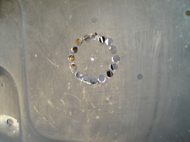
Both holes are now finished, the irregular stamping shape around the hole on the right would have made using a chassis punch impossible anyway.
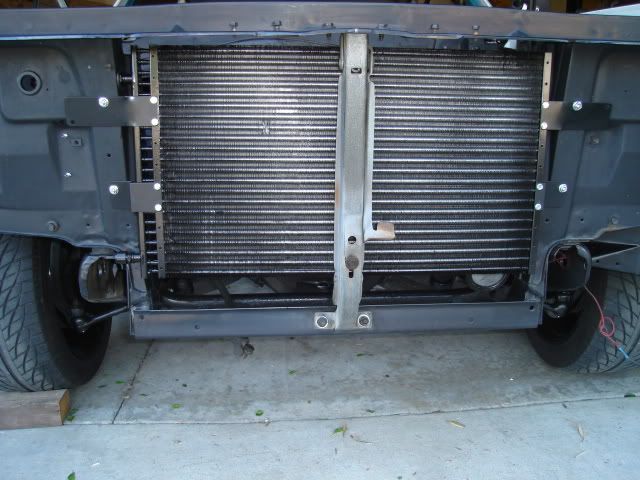
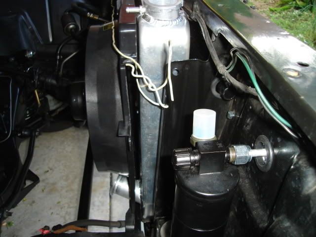
Drier mounted inside the core support, the 1.25" hole (1" rubber grommet now installed) lines up the inlet port on the drier.
Condensor is now bolted in place, the 4 mounting brackets supplied in the kit lined up perfectly with the 4 existing holes in the core support.
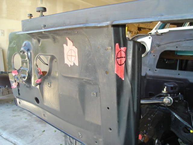
I did a test fit of the main A/C and heater unit under the dash. Two existing holes in the firewall serve to locate it and hold it in place along with two small brackets that bolt under the bottom edge of the dash. I needed to drill a 3/4" hole for the evaporator water drain tube and I wanted to make sure everything lined up before I drilled the hole.
I climbed back inside and removed the old firewall pad and wiped down the inside of the dash and firewall. Also removed the e-brake mechanism and the water temp and oil pressure gauges that were hanging under the dash, everything is now out of the way so I can start putting some new firewall insulation down.
Set my new reproduction Chevelle engine mount brackets on the front crossmember just long enough to find out that I'll need to set the engine and trans in place in order to locate them. None of the holes that mounted the old Pontiac mount brackets line up with the new mount brackets.
Little by little it's all starting to come together.
The radiator core support needed two 1.25" holes drilled in it so the hoses can pass through it. Measurements for the hole locations are in the kit installation instructions.
Since I don't have a 1.25" diameter chassis punch in my tool collection I drilled a series of smaller holes right next to one another. After knocking it out I finished it to size with a half-round file and painted the bare metal edges of the hole. Even if I had a large 1.25" drill bit using one would have torn up the sheetmetal when it broke through.
Both holes are now finished, the irregular stamping shape around the hole on the right would have made using a chassis punch impossible anyway.
Drier mounted inside the core support, the 1.25" hole (1" rubber grommet now installed) lines up the inlet port on the drier.
Condensor is now bolted in place, the 4 mounting brackets supplied in the kit lined up perfectly with the 4 existing holes in the core support.
I did a test fit of the main A/C and heater unit under the dash. Two existing holes in the firewall serve to locate it and hold it in place along with two small brackets that bolt under the bottom edge of the dash. I needed to drill a 3/4" hole for the evaporator water drain tube and I wanted to make sure everything lined up before I drilled the hole.
I climbed back inside and removed the old firewall pad and wiped down the inside of the dash and firewall. Also removed the e-brake mechanism and the water temp and oil pressure gauges that were hanging under the dash, everything is now out of the way so I can start putting some new firewall insulation down.
Set my new reproduction Chevelle engine mount brackets on the front crossmember just long enough to find out that I'll need to set the engine and trans in place in order to locate them. None of the holes that mounted the old Pontiac mount brackets line up with the new mount brackets.
Little by little it's all starting to come together.
05-25-2009, 10:46 PM
#104
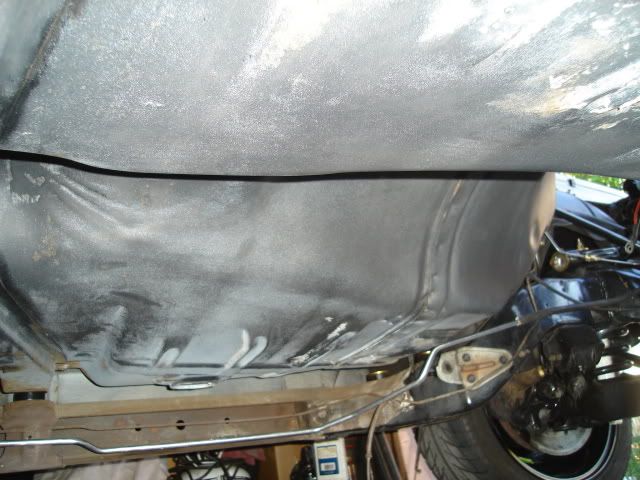
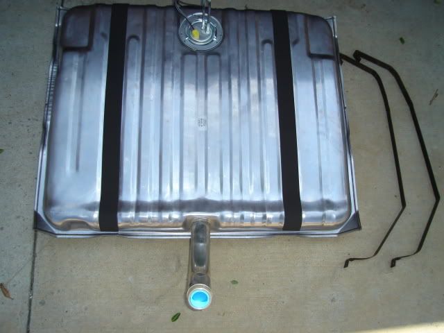
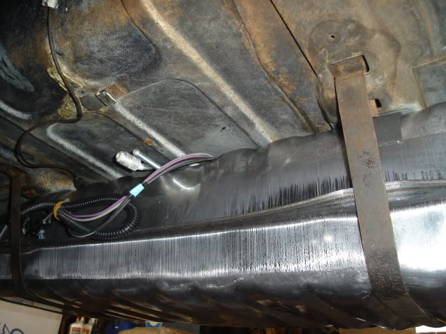
Today I installed the new Spectra Premium Industries fuel tank, it's ready to go for EFI setups with a built-in fuel pump and tank level sender already installed. The tank filler neck needed a little adjustment to the side, some carefull bending put it where it belonged after the tank was in place (easier to do before installation, but harder to see just how much to bend it)
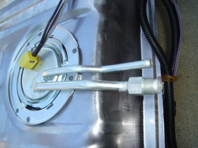
Pump and sender unit with the fuel feed and return lines and the pump and sender wiring.
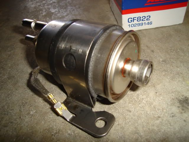
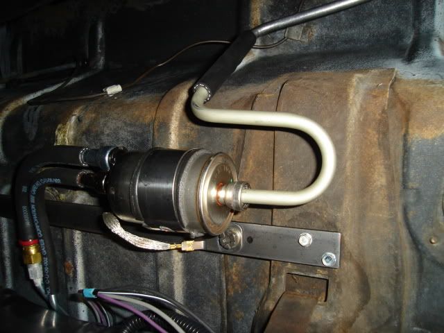
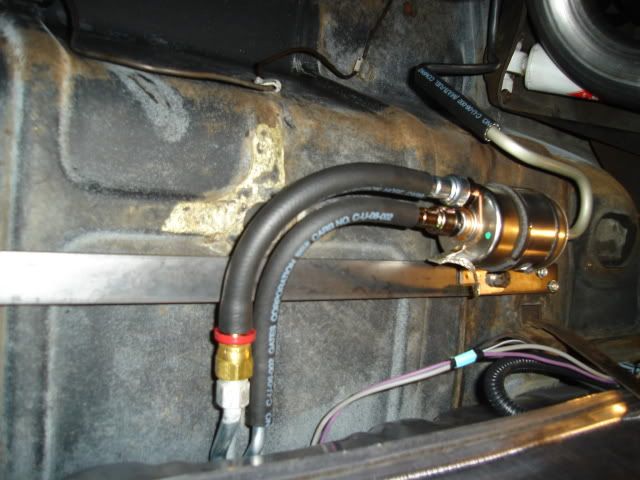
AC Delco GF822 fuel return regulator and filter unit for a late-model Corvette.
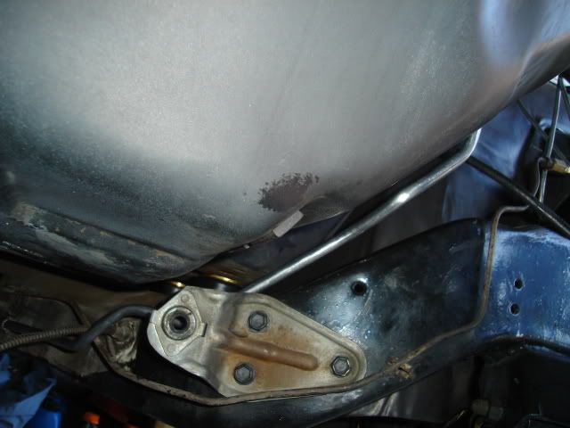
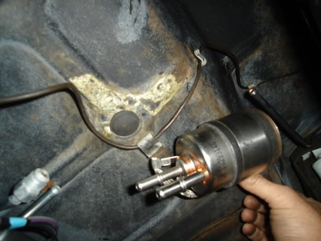
The regulator/filter will need to mount up here somewhere, as soon as I get a few of the pieces I need to connect everything up I'll find the right spot for it.
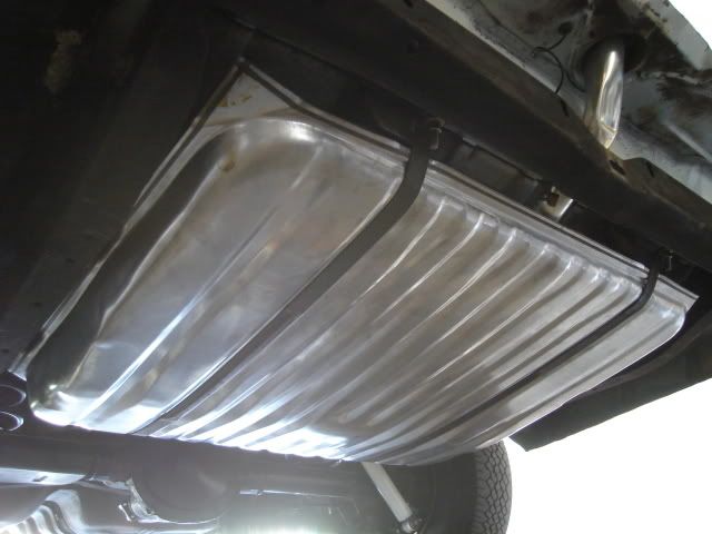
A look from the front side of the tank.
Tank install is complete, the only real hitch other than the filler neck being a bit off to the side was having to replace the two 3" long carriage bolts that tighten the tank straps at the rear. The straps wouldn't quite reach up far enough so I could put the bolts through the straps. I had to scrounge a couple of 4" long hex head bolts to use in the meantime, I'll go to the hardware store and get two 3/8-16 X 4" carriage bolts later to replace them.
That's all for this 3-day weekend, The Tempest waits patiently until the next round of activity among the other cars and parts.
Pump and sender unit with the fuel feed and return lines and the pump and sender wiring.
AC Delco GF822 fuel return regulator and filter unit for a late-model Corvette.
The regulator/filter will need to mount up here somewhere, as soon as I get a few of the pieces I need to connect everything up I'll find the right spot for it.
A look from the front side of the tank.
Tank install is complete, the only real hitch other than the filler neck being a bit off to the side was having to replace the two 3" long carriage bolts that tighten the tank straps at the rear. The straps wouldn't quite reach up far enough so I could put the bolts through the straps. I had to scrounge a couple of 4" long hex head bolts to use in the meantime, I'll go to the hardware store and get two 3/8-16 X 4" carriage bolts later to replace them.
That's all for this 3-day weekend, The Tempest waits patiently until the next round of activity among the other cars and parts.
05-25-2009, 11:30 PM
#105
On The Tree
iTrader: (1)

Join Date: Oct 2008
Location: NE PA
Posts: 181
Likes: 0
Received 0 Likes
on
0 Posts

It's looking good Bart. You must have had one busy weekend. I think you can start to see some light at the end of the tunnel. I can't wait to see the end result. You probably can't either.
Rich
Rich
05-31-2009, 01:38 AM
#106
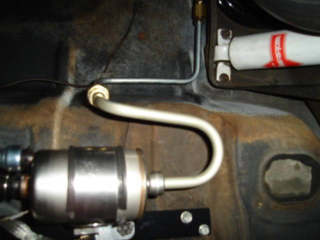
Mounted the fuel regulator/filterand connected everything up with Gates fuel injection hose, pricey stuff at about $7 a foot but it should last pretty long before it needs replacing.
The filter uses quick disconnect push-in fittings common to late model cars and completely new to me. I bought a 12" long piece of 3/8" tubing with quick disconnect ends formed on both ends (about $10) and bent it so it would meet up with the 3/8" pre-formed reproduction chassis fuel line. I cut the quick disconnect feature off the end that connects to the chassis line and used a flaring to tool to form a bead on the end somewhat like the end on a factory line to retain the fuel hose better after it's clamped.
The repro line only needed a 90 degree downward bend added as close to the end as possible. I didn't need cut the end off the line was able to keep the beaded end. At this point none of the hose clamps have been installed.
I bought 2 push-on quick disconnect fittings (about $8 each) to mate the 3/8" inlet and 5/16" return on the filter to the tank fuel pump lines. The tank lines come with fittings already made to accept rubber fuel injection hose, the new quick disconnect fittings went on the filter so that fuel injection hose would connect up to it.
I hung the new 2-1/2" tailpipes temporarily to make sure I was keeping my lines as far away from the hot exhaust as possible. The filter mounts on a 22" long piece of 1" X 3/16" mild steel strap, it mounts to the structure underneath the trunk pan that supports the fuel tank. The filter mounting bracket was removed and painted black after these pics were taken.
After doing some measuring on the engine I came up with the final configuration for the fuel line end on the engine side of the system. I took the line loose from the chassis clips and pulled it down far enough that I could use a tubing bender on it and put a 90 degree forward bend at the very end, again keeping the beaded end. It was bent a couple of inches toward the driver's side and then secured with an Adel clamp. Had to get this done before the engine goes in, no way to get the bender in after that is in there.
Still need to fab a couple of blockoff plates to close up the holes where the throttle cable and pedal pivot used to mount on the firewall as you can see in the above pic.
Mounted the readjusted the rear bumper today as well, the body has dropped down by about 1/4" after installing the new poly body mounts. That's a good thing because it makes the car look a little lower and every little bit helps.
06-01-2009, 12:12 AM
#107
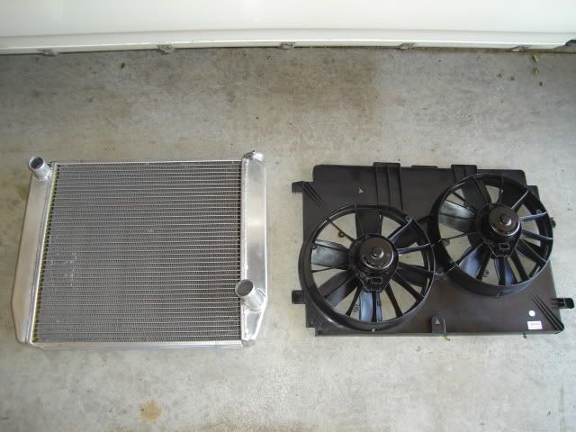
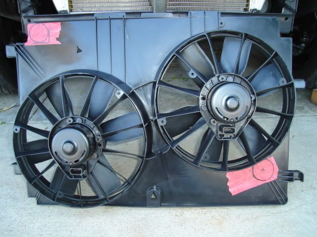
Today's task was to mount the radiator and fans. Here's a look at the 24" wide Griffin universal aluminum radiator and OEM replacement late 4th-gen F-body twin fans and shroud assembly from Dorman.
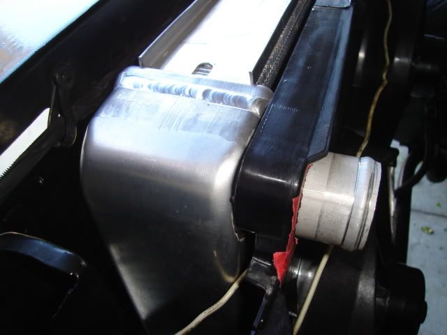
Fabricated some suitable mounts for the radiator using some old 3-row radiator mounting brackets left over from my '64 GTO. I did a little blacksmithing and reconfigured the shape of the saddle, the original unmodified one is on the right. I was able to reuse the lower rubber insulators that were already on the Tempest core support which is made for the 2" taller heavy-duty and A/C radiators.
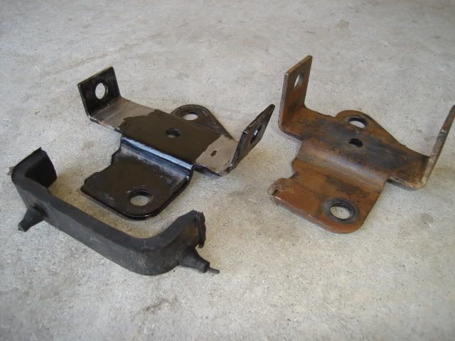
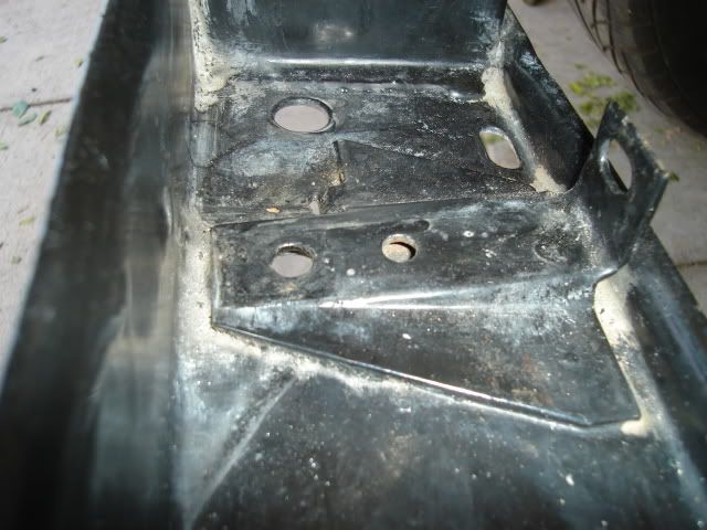
A look at the 4-row radiator mounts that are welded in place at the factory on A/C core supports, the bolt-in ones that I am using now are only used on the standard non-A/C radiator supports.
The newly reconfigured mount with the insulator installed being checked for fit.

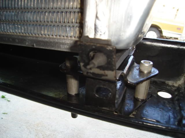
In order to put the radiator at the correct height in relationship to the core support opening I made some tubular standoffs from some thickwall 1/2" O.D. stainless tubing just a tad over 1" long. Now the radiator core is centered from top to bottom in the core support opening, the radiator core itself happens to be exactly the same size as the opening (purely luck). After carefully moving things around to find the ideal location I drilled the four 5/16" mounting holes.
Passenger side looking from the engine side. This one is mounted directly over the old mount.
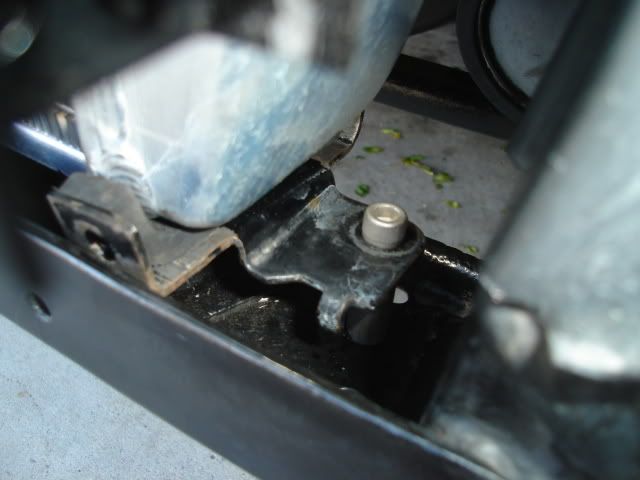
Driver's side looking from the front. This one was mounted 1" to the driver's side instead of directly over the old mount, this is just how everything happened to fit right.
Radiator is now in it's proper place and held at the top for now with a piece of wire, I still have to fabricate the top center support bracket.
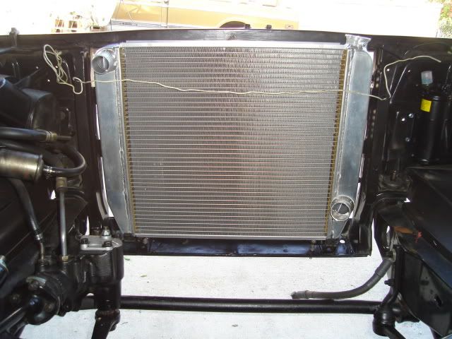
Fan package with radiator hose holes marked for cutting. The 18" height of the shroud exactly matched the height of the core, good luck is again with me. The 26" shroud width matches up exactly with the width of the opening in the core support too.
Holes have been cut and the unit is set in place to check fit.
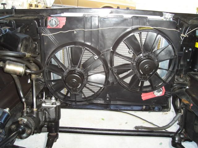
Looking from the passenger side you can see where I'll need to come up with some filler pieces to bridge the gap between the core support and the fan shroud.
The shroud will need the 4 corners notched some to bring the shroud in a little tighter to the radiator, by almost 1/2".
That's all for this weekend.
Stayin' on it.
Fabricated some suitable mounts for the radiator using some old 3-row radiator mounting brackets left over from my '64 GTO. I did a little blacksmithing and reconfigured the shape of the saddle, the original unmodified one is on the right. I was able to reuse the lower rubber insulators that were already on the Tempest core support which is made for the 2" taller heavy-duty and A/C radiators.
A look at the 4-row radiator mounts that are welded in place at the factory on A/C core supports, the bolt-in ones that I am using now are only used on the standard non-A/C radiator supports.
The newly reconfigured mount with the insulator installed being checked for fit.
In order to put the radiator at the correct height in relationship to the core support opening I made some tubular standoffs from some thickwall 1/2" O.D. stainless tubing just a tad over 1" long. Now the radiator core is centered from top to bottom in the core support opening, the radiator core itself happens to be exactly the same size as the opening (purely luck). After carefully moving things around to find the ideal location I drilled the four 5/16" mounting holes.
Passenger side looking from the engine side. This one is mounted directly over the old mount.
Driver's side looking from the front. This one was mounted 1" to the driver's side instead of directly over the old mount, this is just how everything happened to fit right.
Radiator is now in it's proper place and held at the top for now with a piece of wire, I still have to fabricate the top center support bracket.
Fan package with radiator hose holes marked for cutting. The 18" height of the shroud exactly matched the height of the core, good luck is again with me. The 26" shroud width matches up exactly with the width of the opening in the core support too.
Holes have been cut and the unit is set in place to check fit.
Looking from the passenger side you can see where I'll need to come up with some filler pieces to bridge the gap between the core support and the fan shroud.
The shroud will need the 4 corners notched some to bring the shroud in a little tighter to the radiator, by almost 1/2".
That's all for this weekend.
Stayin' on it.
06-03-2009, 11:24 PM
#108
When you're involved with a big project there will always be mistakes made that need to be corrected.
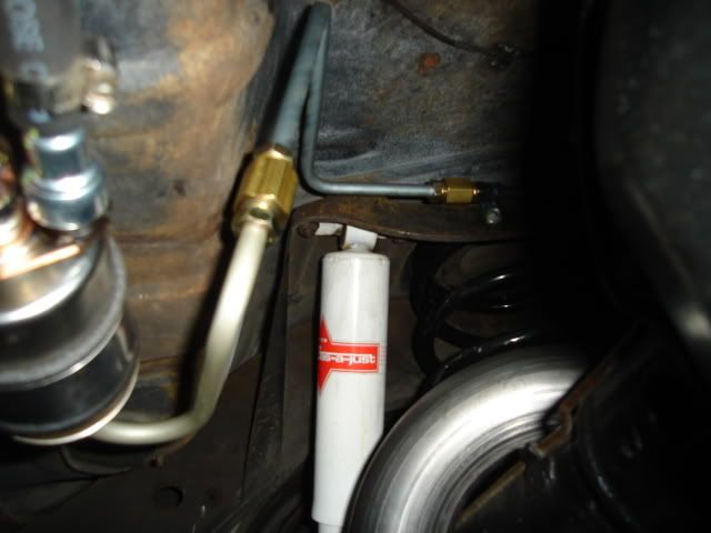
It turns out the exhaust pipe going over the rear axle would have been much too close to my fuel line, when I mocked up the tailpipe location to see if the line would clear it I didn't have it up high enough. I messed around trying to reconfigure the chassis fuel line and just couldn't get it where I wanted it.
I cut off about the last foot of line and got out my flaring tool so I could use an inverted flare union to join it up with a new piece of 3/8" steel line bent in the correct configuration. I put another inverted flare on the piece of line that goes into the filter and joined it up with the newly bent line using another union.
The end result is a lot cleaner-looking than before and eliminates a small piece of rubber fuel hose. Now the tailpipe doesn't even come close to the line, in the picture it has been dropped down so I could access the fuel line.
 06-07-2009, 01:03 AM
#110
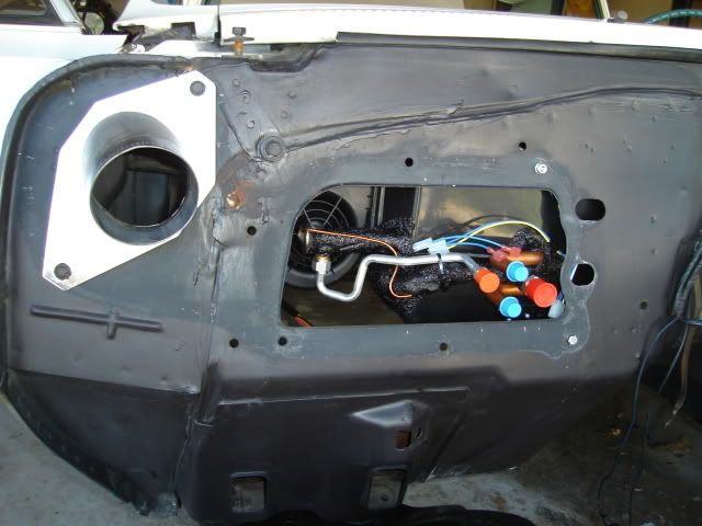
.....and started to mock up the A/C setup into place. I need to have all of the A/C and heat/defrost items that go under the dash in their correct locations so I can find a way to fit the Speartech controller and part of the harness in there. I'll need to find a good location on the firewall for the harness to pass through to the engine compartment.
I need to figure out where everything will go, get it all mounted and then remove all of it. After all of that is done I can finally start installing some high-quality firewall and floor insulation. I'll be using a layer of Damplifier Pro first and then a layer of Luxury Liner Pro on top of that on the inside of the firewall, from Second Skin Audio.
The A/C unit is mounted in place against the firewall with both support brackets installed on the dash bottom edge.
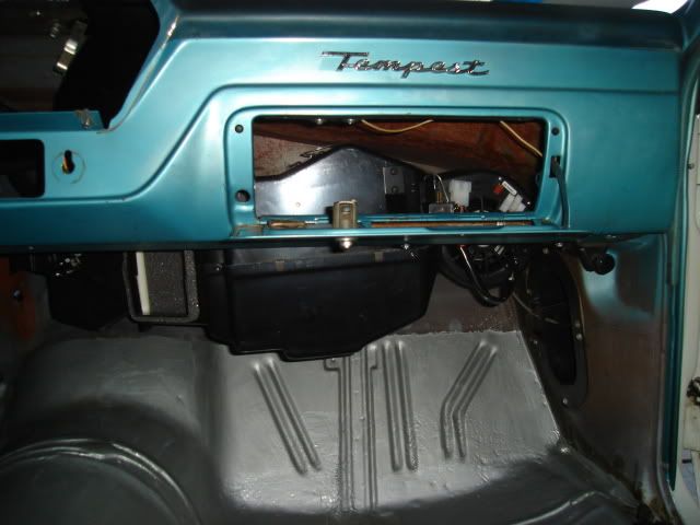
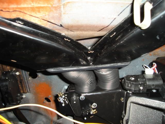
Heater and defrost ducting in place. The original defrost ducting was cut off on the bottom and a defrost hose adapter added from the kit.
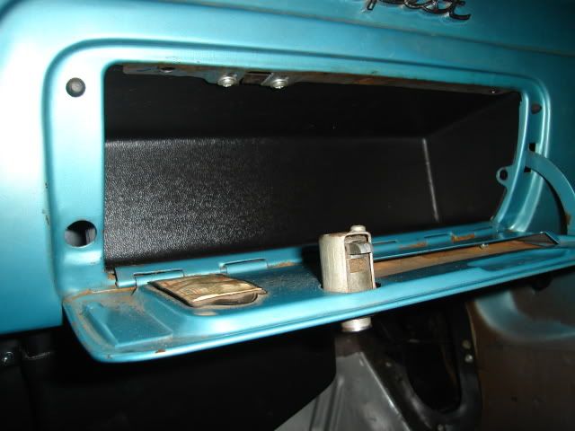
Here's the 'stubby' glovebox insert that's supplied in the kit.
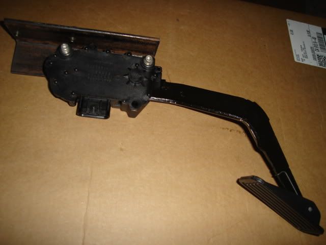
After putting most of the A/C stuff in place I started on the controller and harness. First thing to do will be mounting the drive-by-wire accellerator pedal.
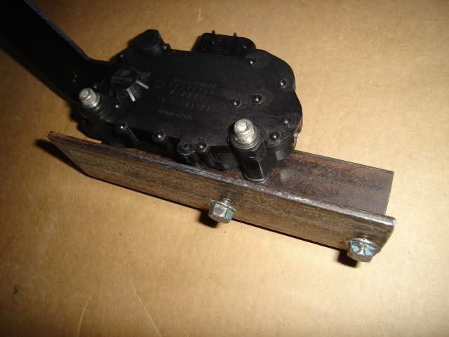
Here are some shots of the accellerator pedal mounted to a bracket I made up out of 2" X 3/16" angle iron that's 7-1/2" long, it's plenty stout and won't flex. I drilled tapped the bracket with 5/16-18 coarse thread for the two bolts that mount it to the firewall and 1/4-28 fine thread 2 places to mount the pedal assembly to the bracket.
Later on the bracket will get cleaned up some by removing some unnecessary metal in a few places and rounding off the corners, a little black paint will finish it off.
The pedal bracket mounts at the very top inside the firewall using two existing bolt holes (opened up to 5/16") that were originally used to mount the voltage regulator.
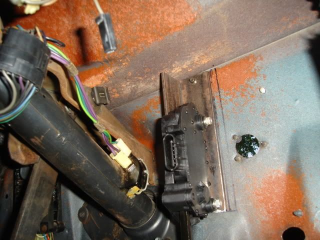
Firewall side showing the two bolts I used to attach the bracket. They're actually stock Pontiac V8 valve cover bolts with flanged heads. Keep Your GM Car All GM.
There is also a third smaller existing hole you can see at the bottom that was originally used for a small sheetmetal screw. For a little more rigidity I'll put a 10-32 thread hex head bolt there after drilling and tapping the bottom corner of the pedal bracket.
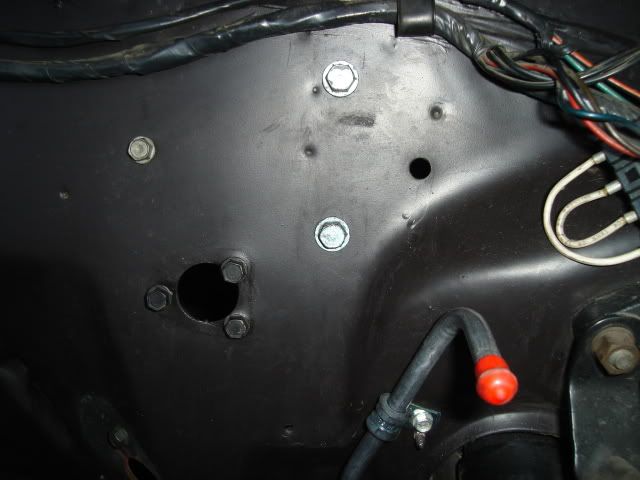
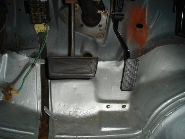
Pedal mounting position is very close to where the original one went.
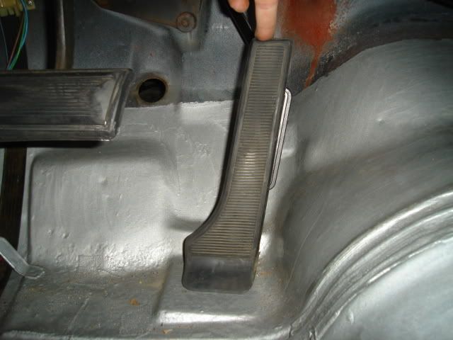
Here you can see how the original pedal sits directly over the new pedal, positioning is right on the money. Later on I may decide to use the original pedal to actuate the throttle, making that work won't be too difficult.
I need to figure out where everything will go, get it all mounted and then remove all of it. After all of that is done I can finally start installing some high-quality firewall and floor insulation. I'll be using a layer of Damplifier Pro first and then a layer of Luxury Liner Pro on top of that on the inside of the firewall, from Second Skin Audio.
The A/C unit is mounted in place against the firewall with both support brackets installed on the dash bottom edge.
Heater and defrost ducting in place. The original defrost ducting was cut off on the bottom and a defrost hose adapter added from the kit.
Here's the 'stubby' glovebox insert that's supplied in the kit.
After putting most of the A/C stuff in place I started on the controller and harness. First thing to do will be mounting the drive-by-wire accellerator pedal.
Here are some shots of the accellerator pedal mounted to a bracket I made up out of 2" X 3/16" angle iron that's 7-1/2" long, it's plenty stout and won't flex. I drilled tapped the bracket with 5/16-18 coarse thread for the two bolts that mount it to the firewall and 1/4-28 fine thread 2 places to mount the pedal assembly to the bracket.
Later on the bracket will get cleaned up some by removing some unnecessary metal in a few places and rounding off the corners, a little black paint will finish it off.
The pedal bracket mounts at the very top inside the firewall using two existing bolt holes (opened up to 5/16") that were originally used to mount the voltage regulator.
Firewall side showing the two bolts I used to attach the bracket. They're actually stock Pontiac V8 valve cover bolts with flanged heads. Keep Your GM Car All GM.
There is also a third smaller existing hole you can see at the bottom that was originally used for a small sheetmetal screw. For a little more rigidity I'll put a 10-32 thread hex head bolt there after drilling and tapping the bottom corner of the pedal bracket.
Pedal mounting position is very close to where the original one went.
Here you can see how the original pedal sits directly over the new pedal, positioning is right on the money. Later on I may decide to use the original pedal to actuate the throttle, making that work won't be too difficult.
Last edited by b-man64; 06-07-2009 at 08:37 PM.
06-07-2009, 09:29 PM
#111
.....was taken care of today, it was easy to keep putting off doing this unpleasant task.
The stock rubber floor mats need some attention before I can put them back in.
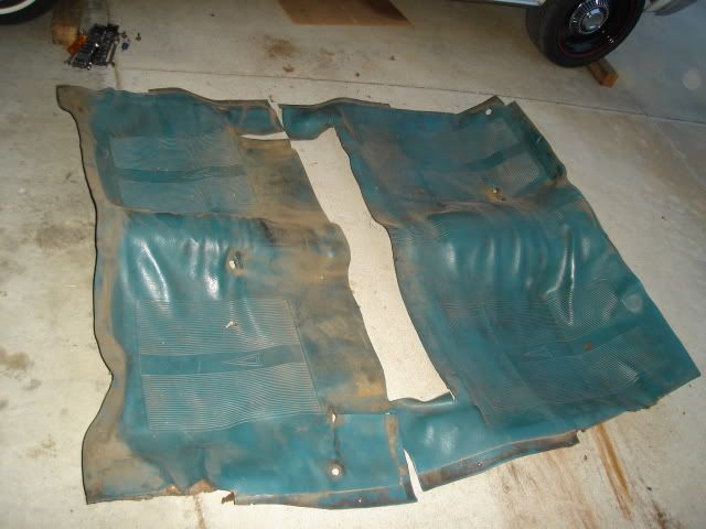
What is left of the old jute padding glued to the backside of the floor mats needed to be carefully scraped off, there are no new replacements available for these mats.
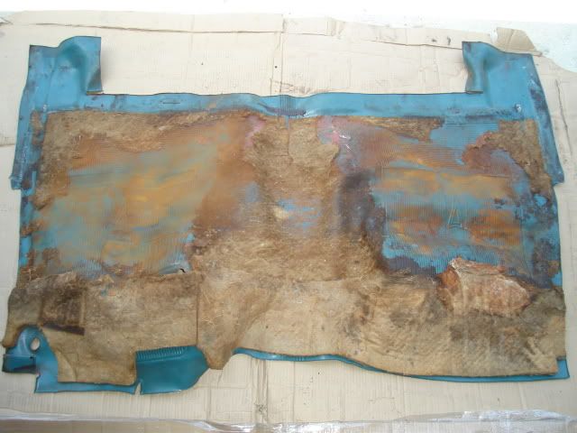
I set the mat in the sun to soften up the old red glue. I was able to scrape most of the old jute and glue off using a plastic spatula of all things, sharp enough to scrape the glue off but not sharp enough to cut through my irreplaceable rubber mat. Some gasoline on a rag was used to remove any remnants of the old glue.
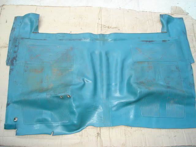
The top side was then scrubbed clean using a small carpet brush and some Simple Green. The color-keyed rubber floor mats used instead of carpet on the low-line Tempest model are just one of the features that add to the charm of these old economy cars.
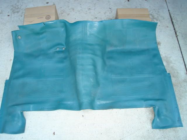
I spent the better part of 5 hours cleaning up the front (shown) and rear mats. I'm pretty sore after all that scrubbing, now I know why I put this off for so long.
These old car projects do take a lot of time and patience.
The stock rubber floor mats need some attention before I can put them back in.
What is left of the old jute padding glued to the backside of the floor mats needed to be carefully scraped off, there are no new replacements available for these mats.
I set the mat in the sun to soften up the old red glue. I was able to scrape most of the old jute and glue off using a plastic spatula of all things, sharp enough to scrape the glue off but not sharp enough to cut through my irreplaceable rubber mat. Some gasoline on a rag was used to remove any remnants of the old glue.
The top side was then scrubbed clean using a small carpet brush and some Simple Green. The color-keyed rubber floor mats used instead of carpet on the low-line Tempest model are just one of the features that add to the charm of these old economy cars.
I spent the better part of 5 hours cleaning up the front (shown) and rear mats. I'm pretty sore after all that scrubbing, now I know why I put this off for so long.
These old car projects do take a lot of time and patience.
06-10-2009, 11:59 PM
#113
.....is getting some attention after waiting patiently for 6 months.
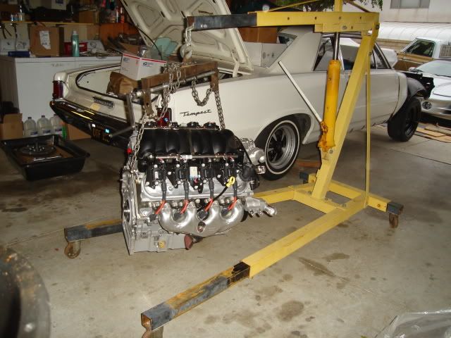
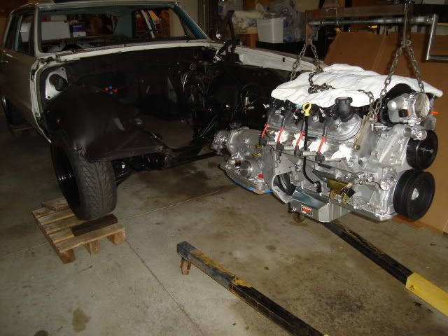
Today right after work I headed to the garage and freed-up my engine stand that had a Pontiac 400 block stored on it and put the LS3 up on the stand. The cast aluminum Corvette oil pan needs to be replaced with a new steel pan from Autokraft so the engine will fit the A-body chassis, so it has to go up on the stand for the pan swap.
I'm hoping to test fit the engine and trans this weekend. I'll remove the core support and slip it all in from the front. It will have to go in and out a few times to locate the engine frame mounts stands and drill the crossmember to install them.
I'm also expecting to do a little hammering on the trans tunnel to clear the fittings for trans cooler lines, and possibly some more dimpling to clear the 3 large bolt bosses at the top of the trans where the main case mates up to the bellhousing.
Waiting for the big weekend.
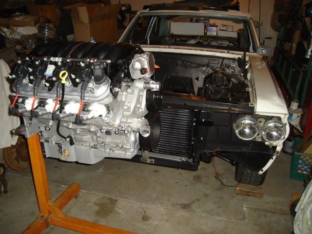
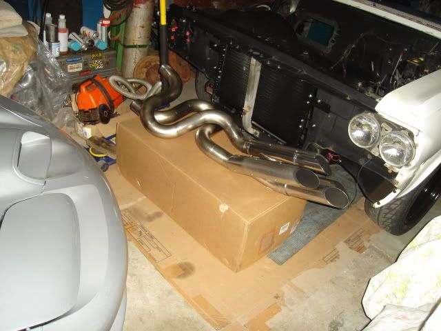
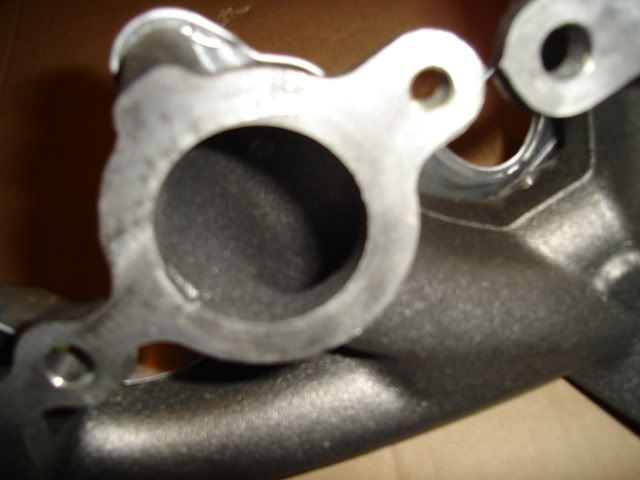
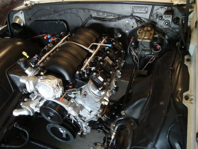
After putting the engine on the stand I pulled off the exhaust manifolds. These are beautifully designed castings with large clean ports that should flow a high volume of exhaust gasses quite nicely. I wish I could use these, but they won't fit my chassis.
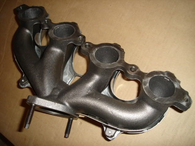
Modern casting technology at its best. The Pontiac V8 guys who use the well-designed factory Ram Air, High Output and Super Duty exhaust manifolds on their performance engines can appreciate these pieces.
Movin' on.
Today right after work I headed to the garage and freed-up my engine stand that had a Pontiac 400 block stored on it and put the LS3 up on the stand. The cast aluminum Corvette oil pan needs to be replaced with a new steel pan from Autokraft so the engine will fit the A-body chassis, so it has to go up on the stand for the pan swap.
I'm hoping to test fit the engine and trans this weekend. I'll remove the core support and slip it all in from the front. It will have to go in and out a few times to locate the engine frame mounts stands and drill the crossmember to install them.
I'm also expecting to do a little hammering on the trans tunnel to clear the fittings for trans cooler lines, and possibly some more dimpling to clear the 3 large bolt bosses at the top of the trans where the main case mates up to the bellhousing.
Waiting for the big weekend.
After putting the engine on the stand I pulled off the exhaust manifolds. These are beautifully designed castings with large clean ports that should flow a high volume of exhaust gasses quite nicely. I wish I could use these, but they won't fit my chassis.
Modern casting technology at its best. The Pontiac V8 guys who use the well-designed factory Ram Air, High Output and Super Duty exhaust manifolds on their performance engines can appreciate these pieces.
Movin' on.
06-13-2009, 01:36 AM
#114
.....after work preparing the engine.
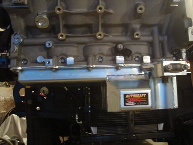
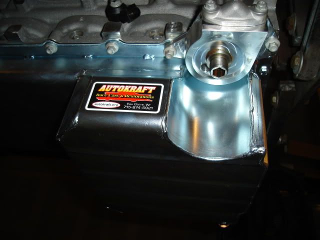
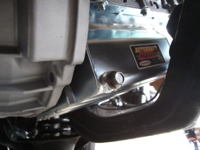
Last night I swapped out the stock oil pan for the Autokraft pan after draining out and saving the 6 quarts of Mobil 1 5W-30 that the LS3 comes charged with. It's the only aftermarket pan that fits the A-body chassis and allows you to keep the oil filter in the stock location.
Both the new pan and pickup fit perfectly, no grinding or filing was necessary. I had to shorten all of the M8 factory pan bolts by about .180" (3/16") because of the thinner Autokraft pan rail, the two bolts that hold the filter adapter in place were left alone. The two long M6 X 135mm bolts at the rear of the pan were replaced with much shorter M6 X 25mm bolts.
The stock oil filter won't fit the threads on the new filter adapter, I still need to find out what filter I need to buy.
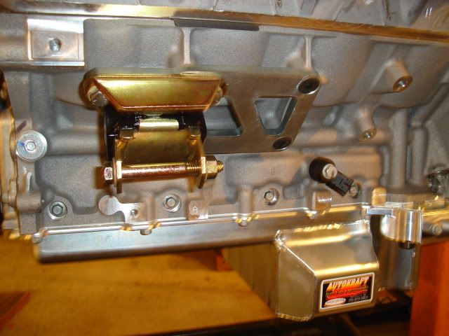
Tonight the Edelbrock engine mount adapter plates were bolted up after doing a slight modification with a half-round file so the 'bump' in engine mount backing plate would clear the inside edge. The file is pointing to the area that needed a little chamfer added.
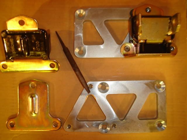
The engine mount adapter plates and Energy Suspension polyurethane engine mounts are now bolted in place using some blue Loctite.
Getting a couple of the little jobs out the way during the week will give me more time for the bigger jobs I need to do this weekend. The weather has been nice and cool for the last few weeks, I have to get as much done as I can before the summer heat hits.
Last night I swapped out the stock oil pan for the Autokraft pan after draining out and saving the 6 quarts of Mobil 1 5W-30 that the LS3 comes charged with. It's the only aftermarket pan that fits the A-body chassis and allows you to keep the oil filter in the stock location.
Both the new pan and pickup fit perfectly, no grinding or filing was necessary. I had to shorten all of the M8 factory pan bolts by about .180" (3/16") because of the thinner Autokraft pan rail, the two bolts that hold the filter adapter in place were left alone. The two long M6 X 135mm bolts at the rear of the pan were replaced with much shorter M6 X 25mm bolts.
The stock oil filter won't fit the threads on the new filter adapter, I still need to find out what filter I need to buy.
Tonight the Edelbrock engine mount adapter plates were bolted up after doing a slight modification with a half-round file so the 'bump' in engine mount backing plate would clear the inside edge. The file is pointing to the area that needed a little chamfer added.
The engine mount adapter plates and Energy Suspension polyurethane engine mounts are now bolted in place using some blue Loctite.
Getting a couple of the little jobs out the way during the week will give me more time for the bigger jobs I need to do this weekend. The weather has been nice and cool for the last few weeks, I have to get as much done as I can before the summer heat hits.
06-14-2009, 04:18 AM
#116
.....and a few steps back today.
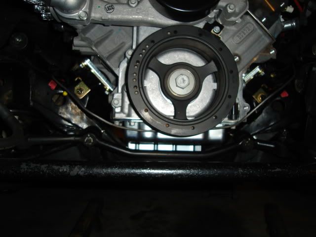
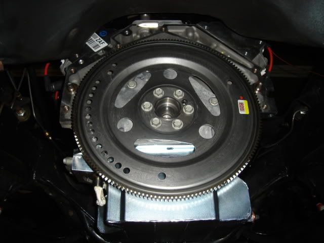
First thing today I installed the new flexplate that I bought to replace the Corvette flexplate that will not work with a standard drivetrain. I took the opportunity to test fit the YANK converter snout into the back of the crank, all was fine.
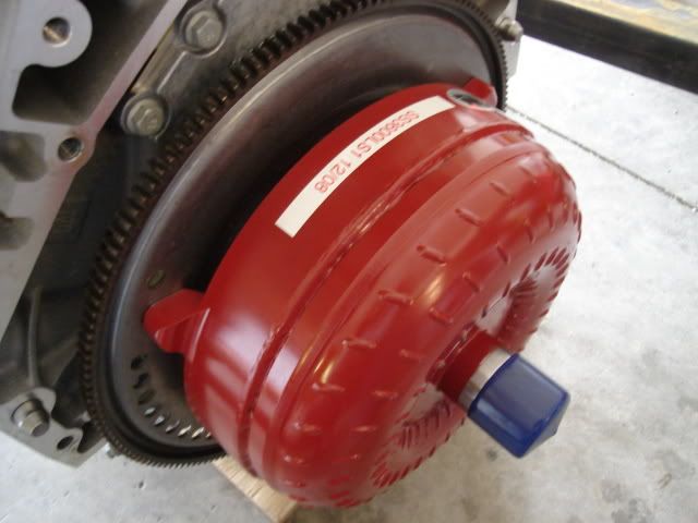
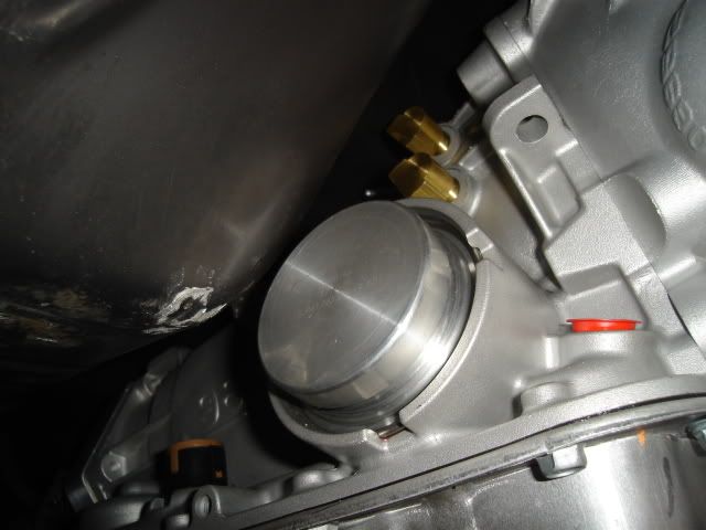
The converter was then primed with fresh trans fluid, I was able to add less than a quart. There was plenty of fluid already in it since the converter and trans were tested together on a transmission dyno.
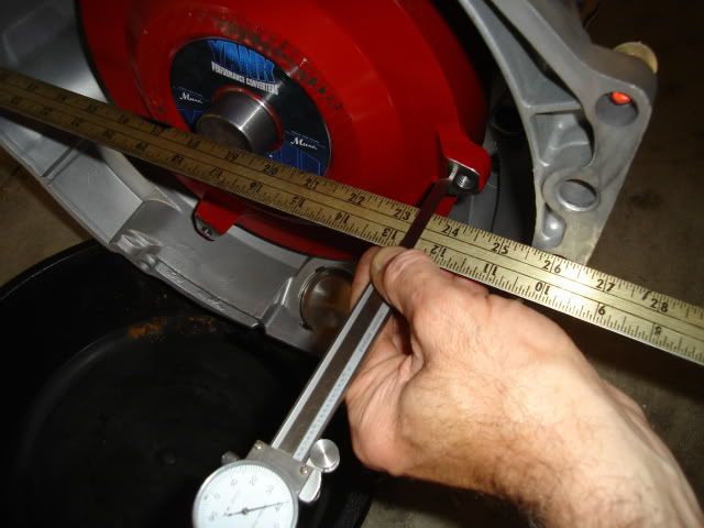
I then measured the distance between the converter mounting lugs and the mounting flange. I did this partly to make sure the converter was seated all the way (it wasn't, it went in another 1/2") and to calculate the need for any shims between the converter lugs and the flexplate.
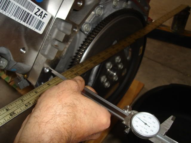
Next I measured the distance from the mounting flange on the block to the face of the flexplate. After doing a little math I found that the converter will need to be pulled towards the engine by .250" in order to mate up to the flexplate, a little too far.
It's best to keep this distance between 1/8" and 3/16" (.125" to .1875") to make sure the converter is engaged far enough into the front pump on the trans. I'll find 3 hardened washers that are exactly the same thickness to get it into spec, something between .060" to .100" thick will work.
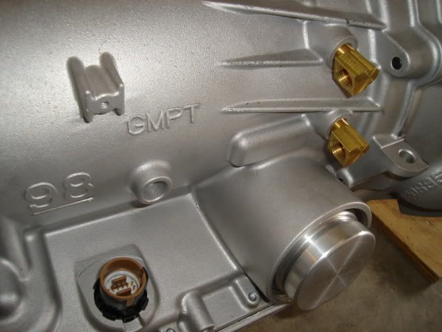
Since clearance inside the trans tunnel will be very tight I removed the straight cooling line fittings and put in a couple of 90 degree fittings. I'll probably loop the trans lines rearward and down before bringing them forward.
Next I bolted the trans up to the engine, hoping that I could put them in as a unit.
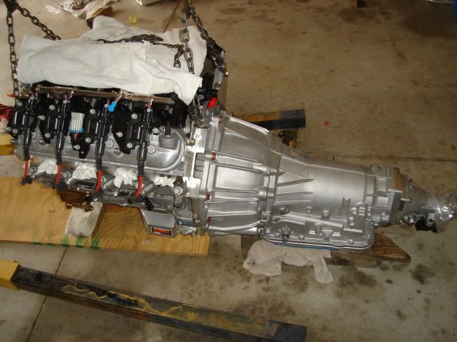
Here goes nothing.
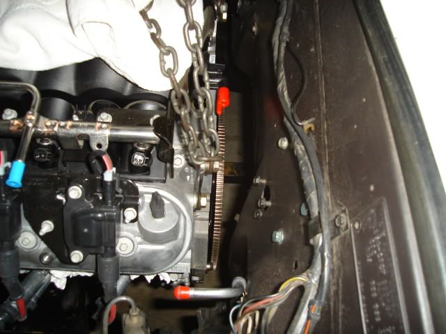
This is as far as it will go, the pan won't clear. The trans is stopped against the top of the tunnel.
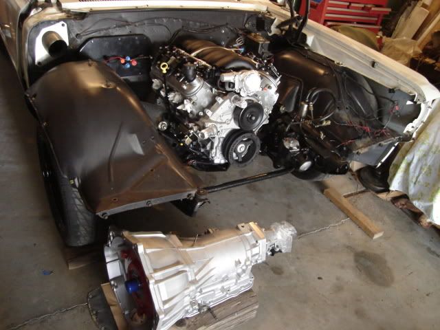
Very close here too, it's time to remove the engine and trans and separate them and put the engine in by itself. I had read that the engine and trans couldn't go in together as a unit but I just had to see for myself.
Engine is back in and is now sitting on the mounts where it needs to be, time to pull it back out and drill some holes for the engine mount stands.
Mounts are now bolted in place on the crossmember and the brake line reconfigured to clear the new mount locations.
Engine has been set back in place on the freshly installed mount stands. I'll leave it supported by the engine hoist overnight with a floor jack under the back of the oil pan for insurance.
Tomorrow I'll mate the trans up to the engine and do any clearance work necessary on the tunnel (hammer time). I need to figure out where the trans crossmember needs to go, hopefully the original crossmember will work. I'll try to find some time to fit up the headers, I'm hoping they can go in place without removing the engine.
End of a very long, busy day.
First thing today I installed the new flexplate that I bought to replace the Corvette flexplate that will not work with a standard drivetrain. I took the opportunity to test fit the YANK converter snout into the back of the crank, all was fine.
The converter was then primed with fresh trans fluid, I was able to add less than a quart. There was plenty of fluid already in it since the converter and trans were tested together on a transmission dyno.
I then measured the distance between the converter mounting lugs and the mounting flange. I did this partly to make sure the converter was seated all the way (it wasn't, it went in another 1/2") and to calculate the need for any shims between the converter lugs and the flexplate.
Next I measured the distance from the mounting flange on the block to the face of the flexplate. After doing a little math I found that the converter will need to be pulled towards the engine by .250" in order to mate up to the flexplate, a little too far.
It's best to keep this distance between 1/8" and 3/16" (.125" to .1875") to make sure the converter is engaged far enough into the front pump on the trans. I'll find 3 hardened washers that are exactly the same thickness to get it into spec, something between .060" to .100" thick will work.
Since clearance inside the trans tunnel will be very tight I removed the straight cooling line fittings and put in a couple of 90 degree fittings. I'll probably loop the trans lines rearward and down before bringing them forward.
Next I bolted the trans up to the engine, hoping that I could put them in as a unit.
Here goes nothing.
This is as far as it will go, the pan won't clear. The trans is stopped against the top of the tunnel.
Very close here too, it's time to remove the engine and trans and separate them and put the engine in by itself. I had read that the engine and trans couldn't go in together as a unit but I just had to see for myself.
Engine is back in and is now sitting on the mounts where it needs to be, time to pull it back out and drill some holes for the engine mount stands.
Mounts are now bolted in place on the crossmember and the brake line reconfigured to clear the new mount locations.
Engine has been set back in place on the freshly installed mount stands. I'll leave it supported by the engine hoist overnight with a floor jack under the back of the oil pan for insurance.
Tomorrow I'll mate the trans up to the engine and do any clearance work necessary on the tunnel (hammer time). I need to figure out where the trans crossmember needs to go, hopefully the original crossmember will work. I'll try to find some time to fit up the headers, I'm hoping they can go in place without removing the engine.
End of a very long, busy day.
06-14-2009, 11:15 PM
#117
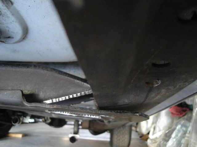
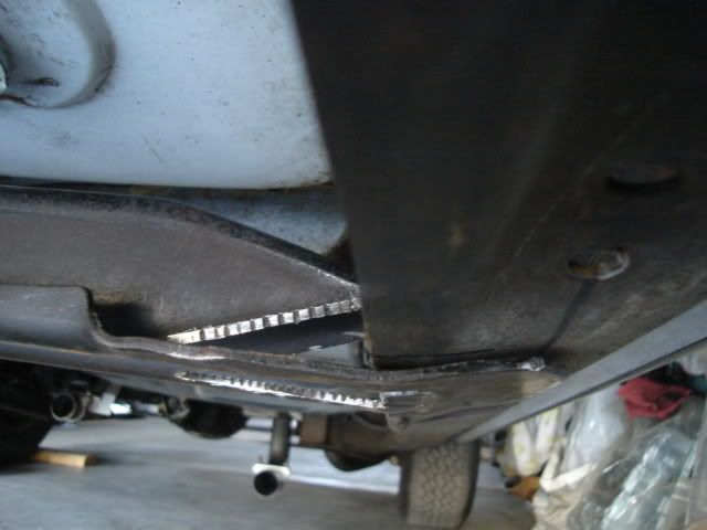
.....that the trans crossmember can no longer sit on top of the bottom section of the frame 'C' channel.
I can't slide the crossmember back far enough to get the trans in the car because it hits the supports for the center body mount on both sides. There's no way to put the trans in first and the crossmember in afterwards unless I change the way the crossmember attaches to the frame.
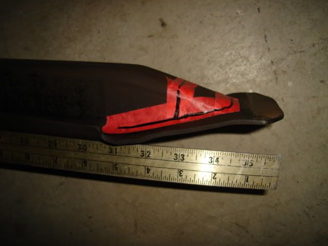
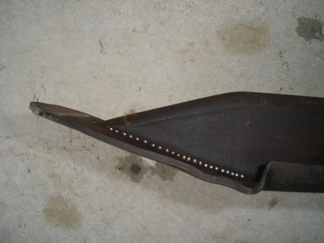
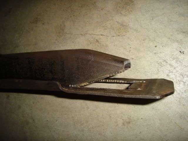
The trans crossmember will need some mods done to the ends to keep the crossmember from sitting too low after I bolt it in from underneath the frame rail instead of having it sit on top of the bottom rail.
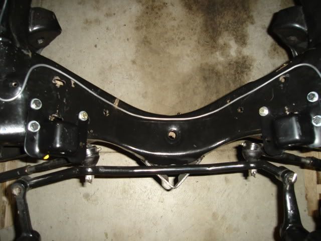
I will make a slice the pretty much right along on the black line at the bottom in the pic and bend the end down so it's even with the bottom of the crossmember and then add a triangular piece to fill the gap. Next I will slice it straight down along the other black line and remove that piece so the frame rail will clear, I can use a piece of 2" X 2" X 3/16" angle iron to fill the gap there. While I'm doing the mods to the crossmember I'll search out a transmission jack to get the trans into the car safely, a floor jack just won't do in this case.
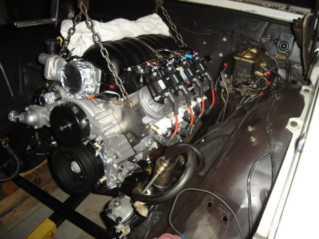
I searched through my scrap metal pile and found an old radiator support crossmember that I made for an old project. I was able to use it as a rear engine support by making a couple of angle iron brackets that attach onto the rear control arm bolts. The oil pan rests on a wood block, this will keep the engine in place while I'm working out the trans fitment and other issues.
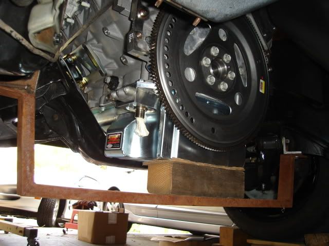
Finally the LS3 is sitting in the car.
That's all for this weekend.
I can't slide the crossmember back far enough to get the trans in the car because it hits the supports for the center body mount on both sides. There's no way to put the trans in first and the crossmember in afterwards unless I change the way the crossmember attaches to the frame.
The trans crossmember will need some mods done to the ends to keep the crossmember from sitting too low after I bolt it in from underneath the frame rail instead of having it sit on top of the bottom rail.
I will make a slice the pretty much right along on the black line at the bottom in the pic and bend the end down so it's even with the bottom of the crossmember and then add a triangular piece to fill the gap. Next I will slice it straight down along the other black line and remove that piece so the frame rail will clear, I can use a piece of 2" X 2" X 3/16" angle iron to fill the gap there. While I'm doing the mods to the crossmember I'll search out a transmission jack to get the trans into the car safely, a floor jack just won't do in this case.
I searched through my scrap metal pile and found an old radiator support crossmember that I made for an old project. I was able to use it as a rear engine support by making a couple of angle iron brackets that attach onto the rear control arm bolts. The oil pan rests on a wood block, this will keep the engine in place while I'm working out the trans fitment and other issues.
Finally the LS3 is sitting in the car.
That's all for this weekend.
Last edited by b-man64; 06-14-2009 at 11:49 PM.
06-15-2009, 11:33 PM
#118
.....the trans crossmember tonight.
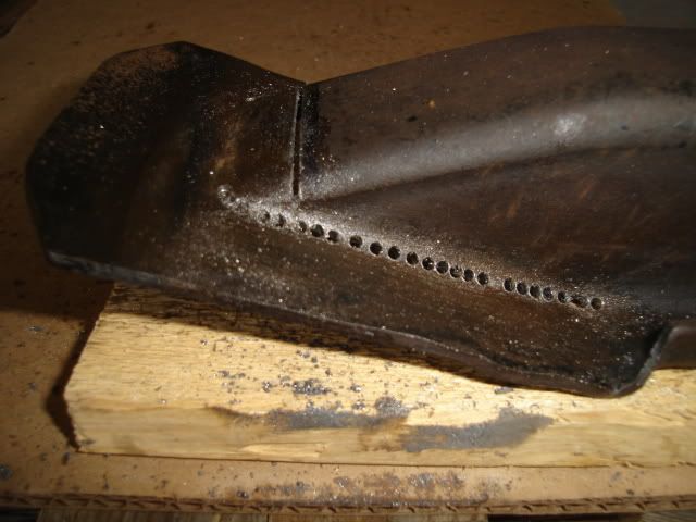
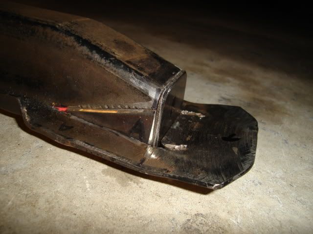
Before any mods.
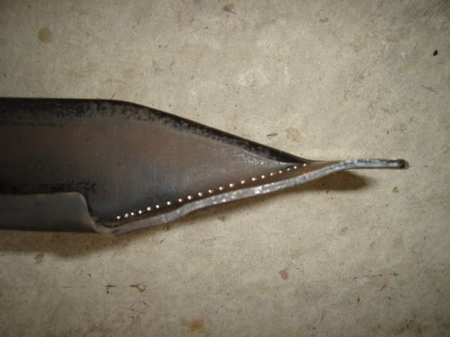
Before doing any cutting I stood the crossmember up in my 6" bench vise and straightened out the tips. Note the series of punch marks where I plan to start drilling some holes.
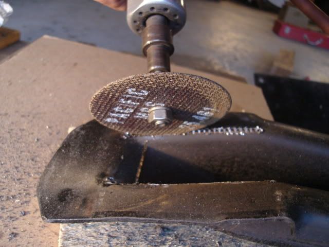
I used a drill that was about the same size as the width of my cutoff wheel to drill the holes. A quick slice with the Sawzall across the end and I'm ready to use the cutoff wheel.
The cutoff wheel work goes quickly and accurately since most of the material on my cut line has been removed by the drilled holes.
Next another trip through the bench vise to bend and straighten out the flanges and make them even with the bottom of the crossmember. Finally I used the vise like a press and flattened out the ends.
That's all for tonight, I'll fit it up under the car to check for fit and cut some filler pieces next.
Before any mods.
Before doing any cutting I stood the crossmember up in my 6" bench vise and straightened out the tips. Note the series of punch marks where I plan to start drilling some holes.
I used a drill that was about the same size as the width of my cutoff wheel to drill the holes. A quick slice with the Sawzall across the end and I'm ready to use the cutoff wheel.
The cutoff wheel work goes quickly and accurately since most of the material on my cut line has been removed by the drilled holes.
Next another trip through the bench vise to bend and straighten out the flanges and make them even with the bottom of the crossmember. Finally I used the vise like a press and flattened out the ends.
That's all for tonight, I'll fit it up under the car to check for fit and cut some filler pieces next.
06-16-2009, 11:28 PM
#119
.....on the crossmember tonight.
Fitted it up and found that the tips didn't match up to the frame.
A little bit of careful bending in the bench vise took care of that.
I scrounged up an old bracket made of flat steel plate that just happened to match up with the .135" material thickness of the crossmember to cut up for the filler pieces. After some work with a Sawzall and grinder it's now ready to weld.
Now to hit up my friend with the MIG welder for a favor.
06-17-2009, 11:58 PM
#120
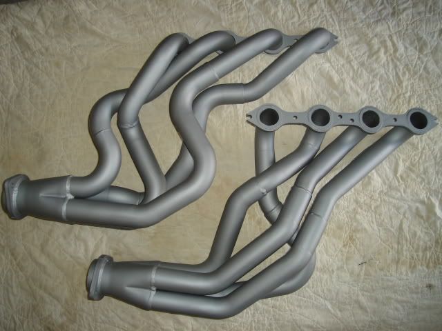
.....from the bottom of the car.
I knew there was probably a 1% chance of them going in, and of course they didn't. The next time the engine is out they'll have to be set in place in the engine bay and the LS3 will have to be carefully dropped down onto the mounts.
Well, at least I took a picture of them.
While I had the exhaust system on my mind I spent a little time modifying the muffler hangers, this pretty much consisted of making a couple brackets from 1-1/4" X 1/8" angle iron to bolt onto the hangers. I need to have a center to center distance of 26" for the muffler outlets and the hangers currently put them at 24".
That's all for tonight, gotta keep chipping away at it.