Pictures of my winter Race car complete re-wiring project

 03-03-2010, 11:49 AM
#62
TECH Resident
Thread Starter
iTrader: (46)

Join Date: Dec 2001
Location: Some where in the Corn Fields of Illinois
Posts: 821
Likes: 0
Received 0 Likes
on
0 Posts

The big tank is for the drysump oiling system.
Regulators are for 2 stages of nitrous and 1 for engine fuel pressure.
Valve covers are from Cary and are actually cast aluminum

427 LSX, ETP C5R heads, 2 stages nitrous, etc etc
Goals? we will see
03-16-2010, 06:25 PM
#65
TECH Resident
Thread Starter
iTrader: (46)
Join Date: Dec 2001
Location: Some where in the Corn Fields of Illinois
Posts: 821
Likes: 0
Received 0 Likes
on
0 Posts
I forgot all about responding to this...
I used .040 carbon for the boards.
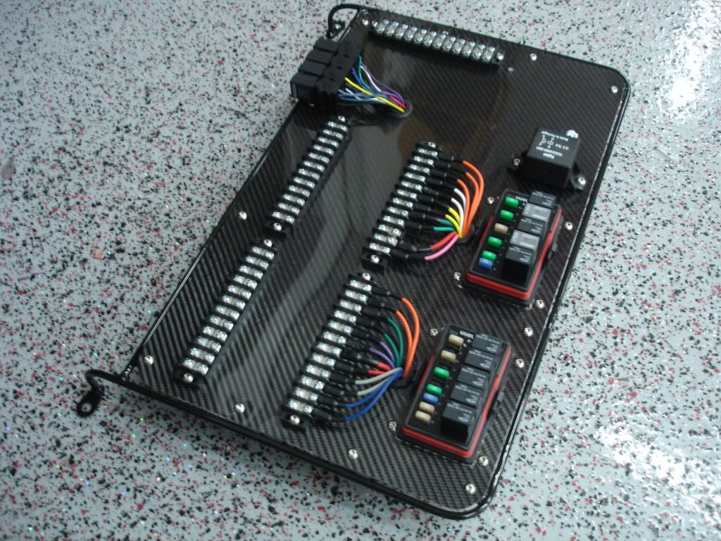
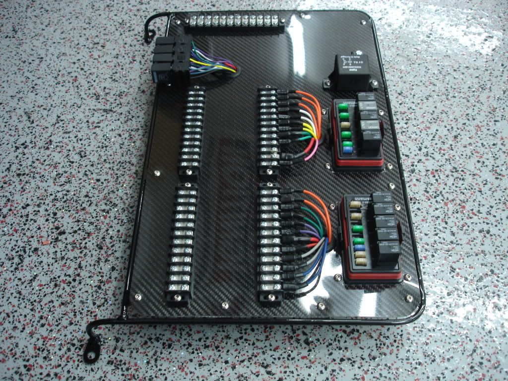
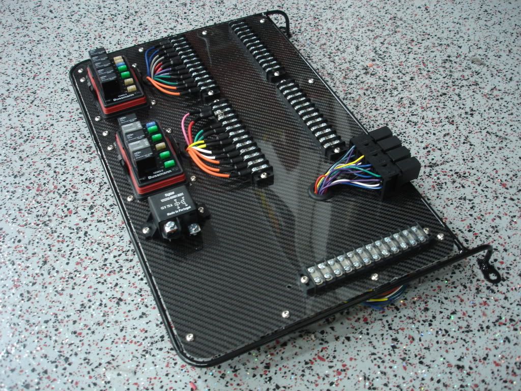
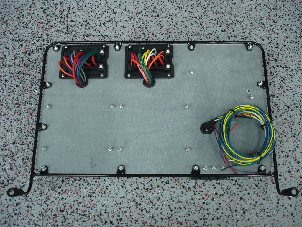
I also have 5 wiring boards completed with the following:
-Tubular support frame, powder coated black
-Carbon panel on top
-2 relay centers wired with all terminals and plugs.
-100A relay for nitrous
-All relays and fuses for relay/fuse panels
-Multiple terminal strips all mounted
-Turn signal wiring kit installed
Basically they are setup with just the wiring to run the relay boards and the rest of the board is empty. If someone wanted to attempt to wire it themselves, you can.
I will have pictures up sometime this week showing the boards if anyone is interested in just buying a simple, ready to wire board.
03-20-2010, 11:14 PM
#66
TECH Resident
Thread Starter
iTrader: (46)
Join Date: Dec 2001
Location: Some where in the Corn Fields of Illinois
Posts: 821
Likes: 0
Received 0 Likes
on
0 Posts
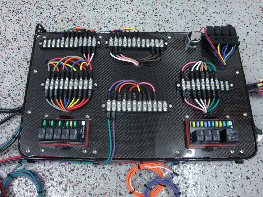
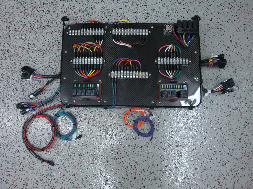
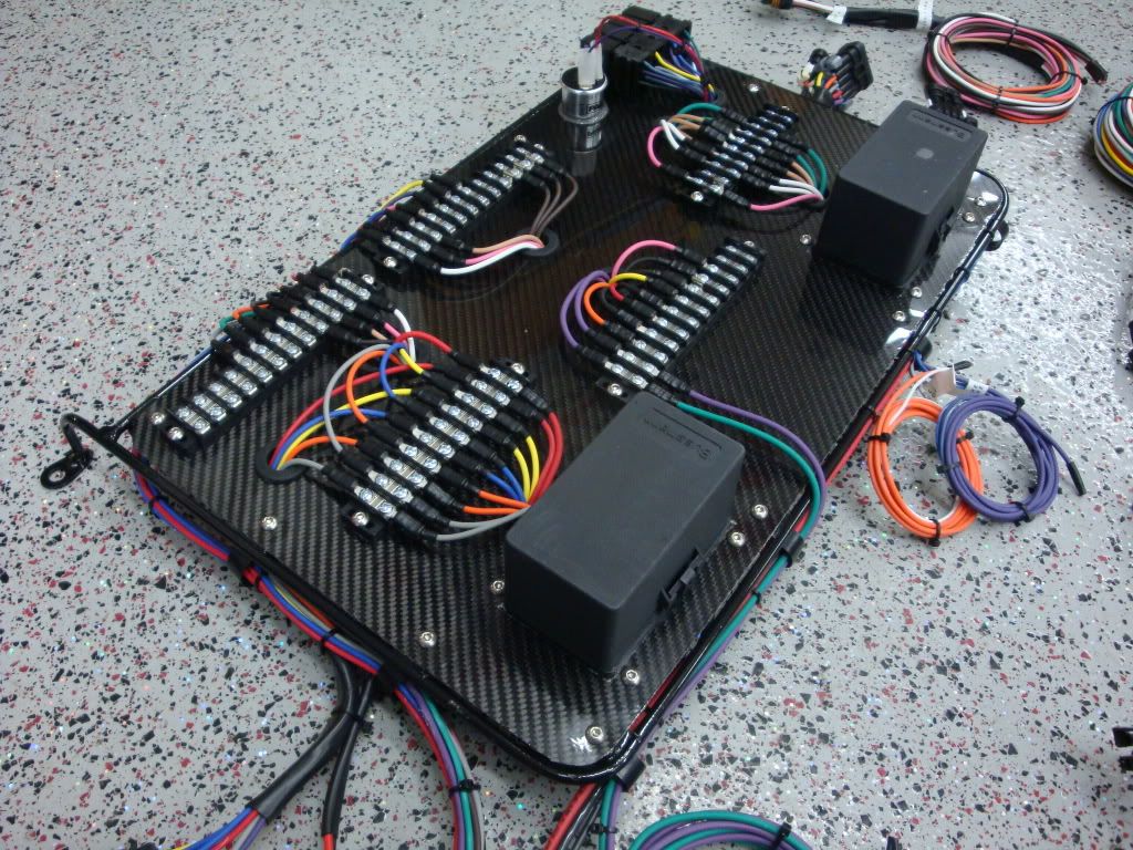
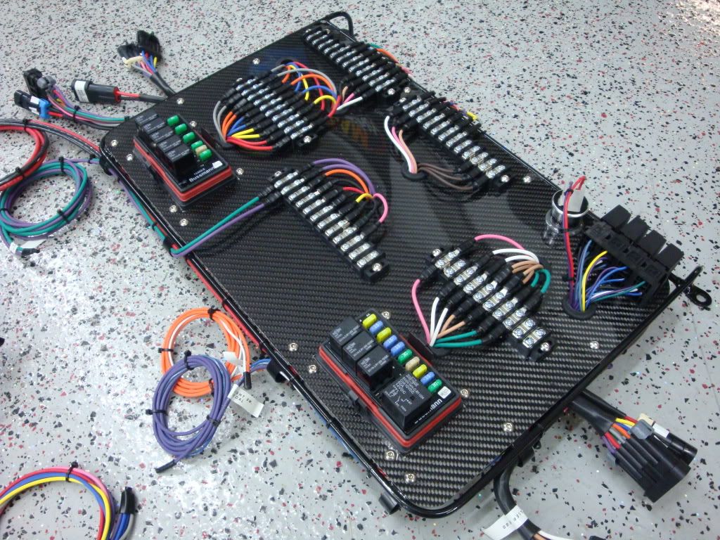
Here are the boards I mentioned in my previous post.
I've got 5 identical boards pre-made just like the pictures below.
All of the relays are wired. Just add your switches and main BAT power to blocks and your good to go. I've also added several switched 12V circuits and BAT fused circuits. On the upper right hand side of the board is the turn signal kit. So, this will control turn signals, hazards if need be, and brake lights.
If anyone is interested, send me a PM.
03-21-2010, 12:09 AM
#67
8 Second Club
iTrader: (9)
Join Date: Oct 2005
Location: Ellicott City,MD
Posts: 1,085
Likes: 0
Received 0 Likes
on
0 Posts
Did you wire the fjo to break the ground directly to the solenoids or the ground on the relays? Reason i was is you have a lot or solenoids and if I recall the fjo can only handle 40amps per stage and nitrous outlets website says one of their nitrous solenoids draws 25amps.
03-22-2010, 02:30 PM
#69

Smkn, I have a question.... if ai gave you a list of everything electric in the car, would it be possible to make a board up?
I'm gonna go over to the darkside and have no need for any nitrous related wiring, and with the linear boost of a supercharger I don't need a boost controller either, so it's not a much more simple setup to wire in alot of ways.
Shoot me a PM, and I can explain what I want/will have in the car.
I'm gonna go over to the darkside
and have no need for any nitrous related wiring, and with the linear boost of a supercharger I don't need a boost controller either, so it's not a much more simple setup to wire in alot of ways. Shoot me a PM, and I can explain what I want/will have in the car.
03-22-2010, 08:02 PM
#70
TECH Resident
Thread Starter
iTrader: (46)
Join Date: Dec 2001
Location: Some where in the Corn Fields of Illinois
Posts: 821
Likes: 0
Received 0 Likes
on
0 Posts
Smkn, I have a question.... if ai gave you a list of everything electric in the car, would it be possible to make a board up?
I'm gonna go over to the darkside and have no need for any nitrous related wiring, and with the linear boost of a supercharger I don't need a boost controller either, so it's not a much more simple setup to wire in alot of ways.
Shoot me a PM, and I can explain what I want/will have in the car.
I'm gonna go over to the darkside
and have no need for any nitrous related wiring, and with the linear boost of a supercharger I don't need a boost controller either, so it's not a much more simple setup to wire in alot of ways. Shoot me a PM, and I can explain what I want/will have in the car.
03-22-2010, 08:05 PM
#71
TECH Resident
Thread Starter
iTrader: (46)
Join Date: Dec 2001
Location: Some where in the Corn Fields of Illinois
Posts: 821
Likes: 0
Received 0 Likes
on
0 Posts
Did you wire the fjo to break the ground directly to the solenoids or the ground on the relays? Reason i was is you have a lot or solenoids and if I recall the fjo can only handle 40amps per stage and nitrous outlets website says one of their nitrous solenoids draws 25amps.
I know for a fact that the FJO has a fairly large margin of error built in, and I've never had an issue with it on my system or any other systems. They can most certainly handle more than 40amps per stage.
03-23-2010, 05:16 PM
#72
8 Second Club
iTrader: (9)
Join Date: Oct 2005
Location: Ellicott City,MD
Posts: 1,085
Likes: 0
Received 0 Likes
on
0 Posts
I usually set them up to break the ground or add the ground (depending on which way you look at it) at the solenoid. That is what the solenoid driver is designed for.
I know for a fact that the FJO has a fairly large margin of error built in, and I've never had an issue with it on my system or any other systems. They can most certainly handle more than 40amps per stage.
I know for a fact that the FJO has a fairly large margin of error built in, and I've never had an issue with it on my system or any other systems. They can most certainly handle more than 40amps per stage.
05-23-2010, 06:54 PM
#73
Registered User

Join Date: May 2010
Posts: 1
Likes: 0
Received 0 Likes
on
0 Posts
Smkn, I have a question.... if ai gave you a list of everything electric in the car, would it be possible to make a board up?
I'm gonna go over to the darkside and have no need for any nitrous related wiring, and with the linear boost of a supercharger I don't need a boost controller either, so it's not a much more simple setup to wire in alot of ways.
Shoot me a PM, and I can explain what I want/will have in the car.
I'm gonna go over to the darkside
and have no need for any nitrous related wiring, and with the linear boost of a supercharger I don't need a boost controller either, so it's not a much more simple setup to wire in alot of ways. Shoot me a PM, and I can explain what I want/will have in the car.
fyi, sorry guys I am a mustang guy, but searching for some good wiring guideline on my 02 stripped down race car, I came across this and HAD to sign up and get involved in this!
this is simply beautiful.....how much for one of the premade panels you already have...and can we talk about pricing on a made to order one like the gentleman i quoted asked?
05-23-2010, 10:53 PM
#74
TECH Resident
Thread Starter
iTrader: (46)
Join Date: Dec 2001
Location: Some where in the Corn Fields of Illinois
Posts: 821
Likes: 0
Received 0 Likes
on
0 Posts
x2 on this.....
fyi, sorry guys I am a mustang guy, but searching for some good wiring guideline on my 02 stripped down race car, I came across this and HAD to sign up and get involved in this!
this is simply beautiful.....how much for one of the premade panels you already have...and can we talk about pricing on a made to order one like the gentleman i quoted asked?
08-20-2010, 03:37 PM
#75
TECH Senior Member
iTrader: (21)
Join Date: Nov 2001
Location: Cecil County Raceway!!!
Posts: 8,484
Likes: 0
Received 0 Likes
on
0 Posts

If you still want windows to go down with the body control module missing, you will be better off to find some manual window doors. The link to a window motor wiring diagram posted by Fireball will not work. The window motors have a special control module that runs the windows. They don't get a straight 12 volts. It appears they either step up the voltage or step it down per the factory wiring schematic. I researched this on a car I wired last fall and experimented with usinig relays and 12 volt signal to the motors. I can 100% guarantee that they don't work with 12 volts. I could wire in the window motor module, but there would be another 20-25 wires to add at least. I've got the PIN outs, but I really didn't want to mess with it at that time.
hmmm...I just did a test on my driver side window motor. I cut the wires at the motor (two thick ones) and used a battery jump box. put one wire on + and the other on - and the window went up just fine. Reversed the polarity and it went down just fine. that circuit I posted should work
09-07-2010, 05:47 PM
#76
TECH Resident
Thread Starter
iTrader: (46)
Join Date: Dec 2001
Location: Some where in the Corn Fields of Illinois
Posts: 821
Likes: 0
Received 0 Likes
on
0 Posts
hmmm...I just did a test on my driver side window motor. I cut the wires at the motor (two thick ones) and used a battery jump box. put one wire on + and the other on - and the window went up just fine. Reversed the polarity and it went down just fine. that circuit I posted should work 
There is a possibility that that motors were burnt up in the car I tested on. I wondered about that at the time because there was no reason for the motors NOT to work even with 12V.
09-07-2010, 05:48 PM
#77
TECH Resident
Thread Starter
iTrader: (46)
Join Date: Dec 2001
Location: Some where in the Corn Fields of Illinois
Posts: 821
Likes: 0
Received 0 Likes
on
0 Posts
Here are some pictures of a control panel for a Mustang with MSD 7531 harness, AMS 1000 harness, turn signals, head lights, brake lights, intercooler pump, fans, water, fuel pumps etc. This one is on its way to Canada right now.