

Project Barney...Turbo T/A

 05-14-2007, 08:04 PM
#62
10 Second Club
Thread Starter
iTrader: (1)
Join Date: Jul 2003
Location: St Petersburg, Fl
Posts: 568
Likes: 0
Received 0 Likes
on
0 Posts
Small update again...
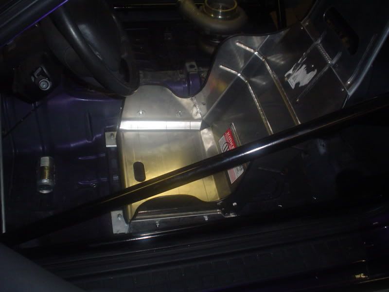
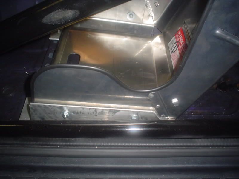
We wanted to at least get the driver's seat in so we built up a bracket for the Kirkey seat. Brackets were made of 4X4 Alluminum angle. The idea was taken from Eric Next's car, although our seats are slightly different. If Eric is reading this... Thanks for your pics.
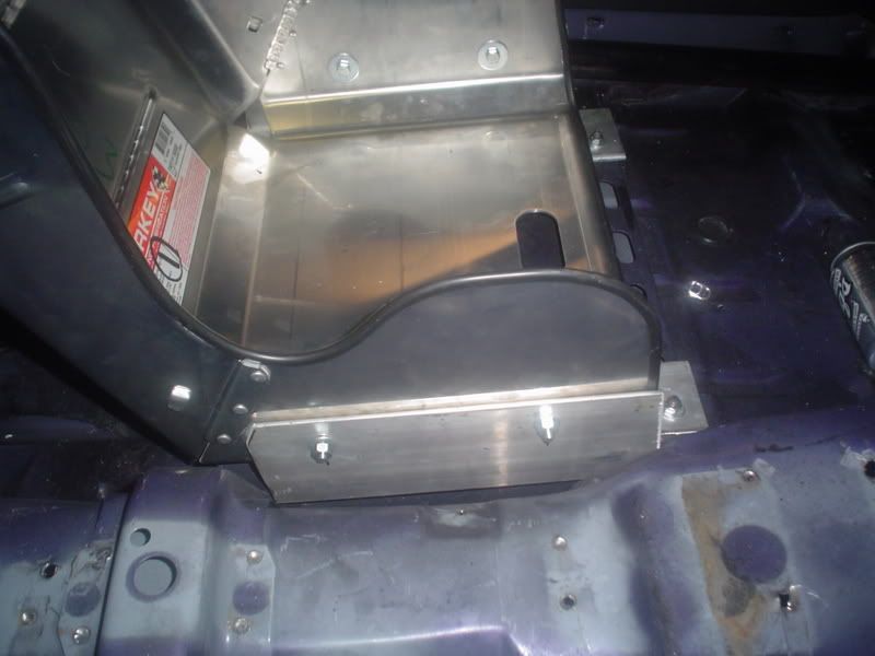
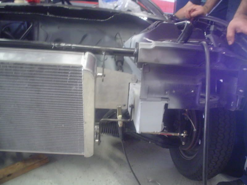
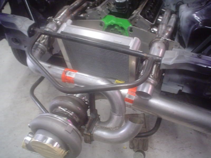
Next, we needed to mount the radiator so we can begin the turbo piping. The radiator needed to be mounted at a backwards angle to make room for the turbo downpipe. Custom brackets were made for this. The radiator actually has NO provisions for mounting, so we had to make our own.
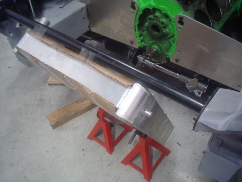
First we positioned the radiator where we wanted it with our ultra high tech holding fixture. The fixture consisted of packing tape and jackstands.
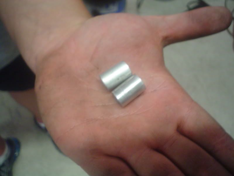
We started by cutting up some alluminum dowel into 4 slugs.
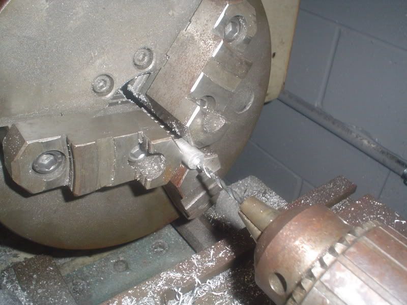
Then we put them in the lathe and drilled the center out and tapped them for bolt mounting.
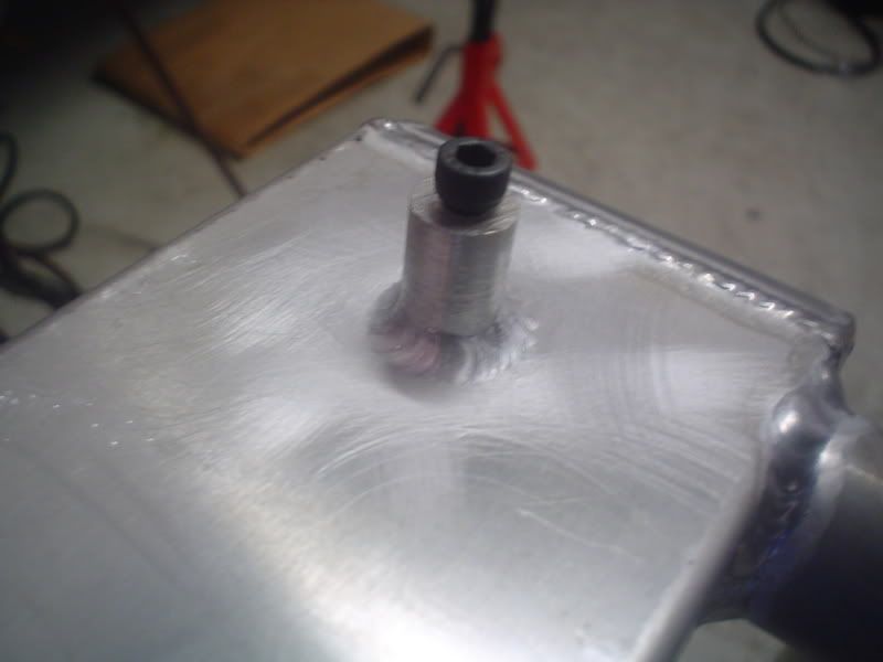
The slugs were then heli-arc'ed onto the side surface of the radiator.
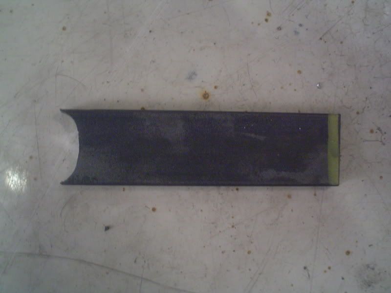
Next we took some flat bar stock and cut two pieces for brackets and drilled a 1 inch hole in the end. The hole was then cut in half to make it weldable to the already existing radiator support.
The two brackets were welded to the radiator support and look like this. These brakets support the top of the radiator.
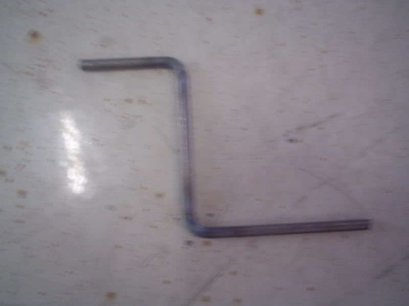
Then we needed some brackets to support the lower portion of the radiator. We wanted something lightweight so I took some steel dowel and bent it into a "Z" Shape.
Then I welded a couple of mounting tabs on the ends of the "Z" bar.
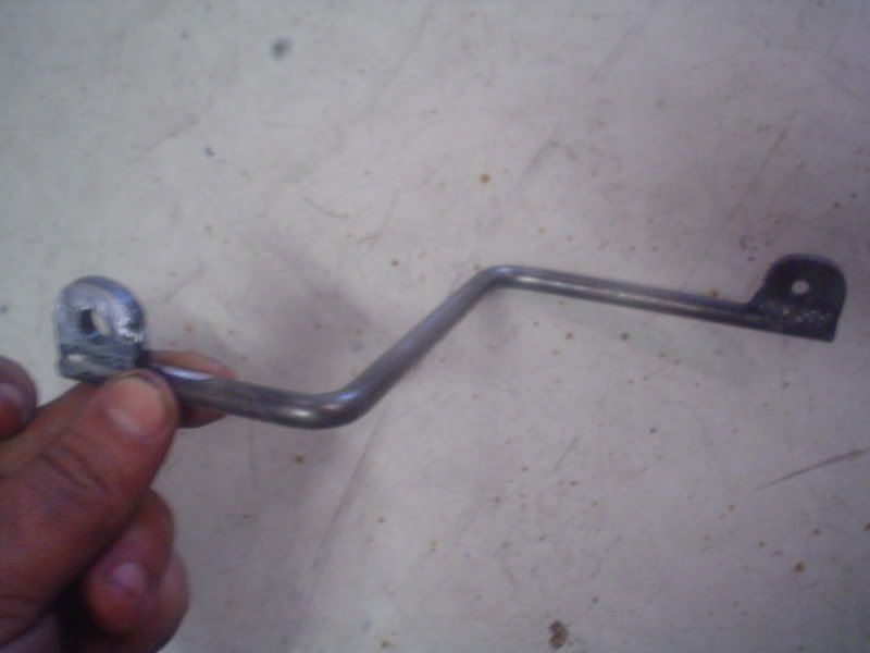
The Z bar attaches to the frame and then to one of our custom mounting posts.
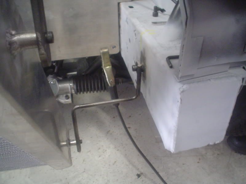
This is a picture of the final radiator mounting.
We also have started the piping for the turbo, but the pictures are not complete. As soon as those are complete I will post up pictures of that. Friday, the Cam showed up. I am not going to give out the specs, but it's not what you'd expect. It is solid roller and not exactly mild. Duration is over 250 on each side (@ .050" lift) and lift is around the 700 area. Sorry, that's all you get. It was custom ground for us by someone that knows what he's doing.
We wanted to at least get the driver's seat in so we built up a bracket for the Kirkey seat. Brackets were made of 4X4 Alluminum angle. The idea was taken from Eric Next's car, although our seats are slightly different. If Eric is reading this... Thanks for your pics.
Next, we needed to mount the radiator so we can begin the turbo piping. The radiator needed to be mounted at a backwards angle to make room for the turbo downpipe. Custom brackets were made for this. The radiator actually has NO provisions for mounting, so we had to make our own.
First we positioned the radiator where we wanted it with our ultra high tech holding fixture. The fixture consisted of packing tape and jackstands.
We started by cutting up some alluminum dowel into 4 slugs.
Then we put them in the lathe and drilled the center out and tapped them for bolt mounting.
The slugs were then heli-arc'ed onto the side surface of the radiator.
Next we took some flat bar stock and cut two pieces for brackets and drilled a 1 inch hole in the end. The hole was then cut in half to make it weldable to the already existing radiator support.
The two brackets were welded to the radiator support and look like this. These brakets support the top of the radiator.
Then we needed some brackets to support the lower portion of the radiator. We wanted something lightweight so I took some steel dowel and bent it into a "Z" Shape.
Then I welded a couple of mounting tabs on the ends of the "Z" bar.
The Z bar attaches to the frame and then to one of our custom mounting posts.
This is a picture of the final radiator mounting.
We also have started the piping for the turbo, but the pictures are not complete. As soon as those are complete I will post up pictures of that. Friday, the Cam showed up. I am not going to give out the specs, but it's not what you'd expect. It is solid roller and not exactly mild. Duration is over 250 on each side (@ .050" lift) and lift is around the 700 area. Sorry, that's all you get. It was custom ground for us by someone that knows what he's doing.
 05-18-2007, 10:46 PM
#64
10 Second Club
Thread Starter
iTrader: (1)
Join Date: Jul 2003
Location: St Petersburg, Fl
Posts: 568
Likes: 0
Received 0 Likes
on
0 Posts
Another small update...
We started working on the headers. Here's a picture of what the header starts out as. It's just a laser cut 3/8" flange and some 1 3/4 mild steel U-Bends.
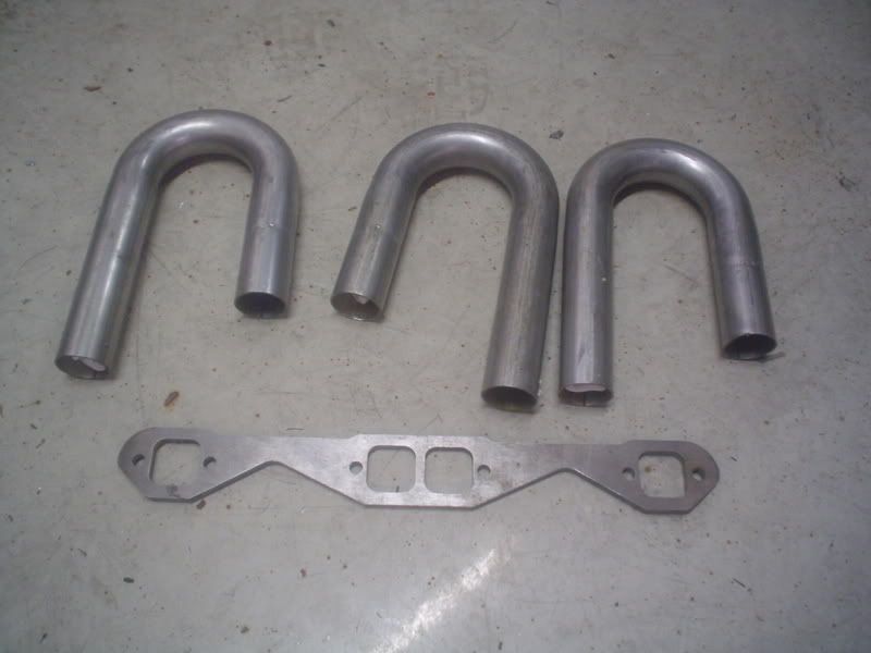
The pieces of bends are cut up to meet our needs and tacked in place to the flange and collector. Here we have 3 of the tubes in place.
As we add tubes we keep doing trial fitments on the mock up motor to make sure everything is going to fit. We also spent time making sure that all the header bolts would be easy to get to. None of the header tubes get in the way of the spark plugs becaue the entire exhaust system goes up. Should make spark plug replacement really easy.
After all our tubes are cut and fitted we set them up on our jig/fixture. It is a 2" block of steel that the header flange bolts to. This will not allow the flange to warp when we weld it up.
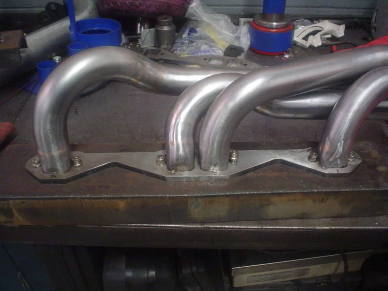
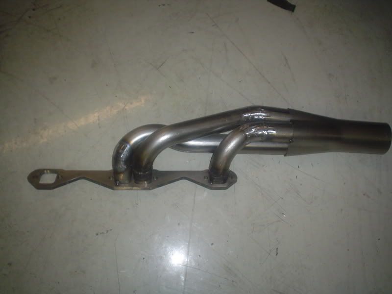
Here is a pictures of the completed header with all the welds ground off and ready to install.
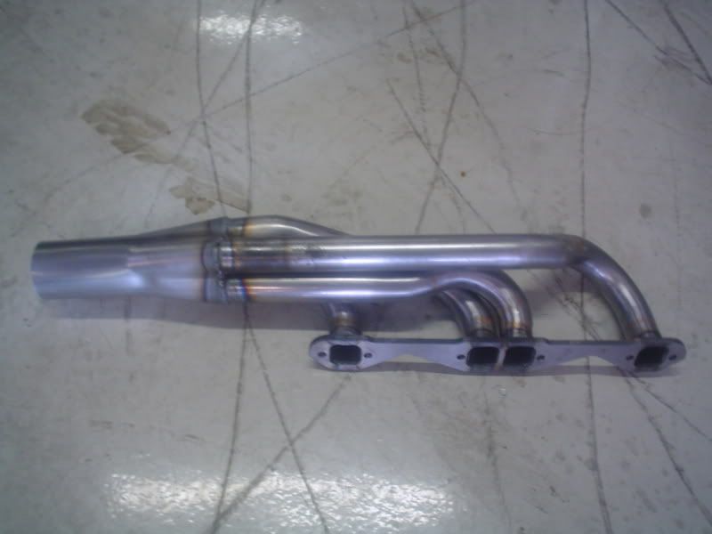
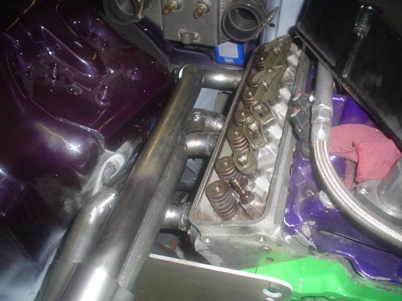
This is a picture of the header test fitted on the motor with the V-Band flange welded on. It all clears, but barely. We're going to cut out part of the shock tower to make sure we have plenty of room. This will also allow us room for the gasket. It will also mean that we don't have to worry about burning the paint.
One more header to go and then we'll pipe it all in to the turbo. After that, we'll pack it all up and send it to the coating shop. We'll be using Procoat here in Tampa. They have a black caoting that should handle the heat.
More updates coming soon.
We started working on the headers. Here's a picture of what the header starts out as. It's just a laser cut 3/8" flange and some 1 3/4 mild steel U-Bends.
The pieces of bends are cut up to meet our needs and tacked in place to the flange and collector. Here we have 3 of the tubes in place.
As we add tubes we keep doing trial fitments on the mock up motor to make sure everything is going to fit. We also spent time making sure that all the header bolts would be easy to get to. None of the header tubes get in the way of the spark plugs becaue the entire exhaust system goes up. Should make spark plug replacement really easy.
After all our tubes are cut and fitted we set them up on our jig/fixture. It is a 2" block of steel that the header flange bolts to. This will not allow the flange to warp when we weld it up.
Here is a pictures of the completed header with all the welds ground off and ready to install.
This is a picture of the header test fitted on the motor with the V-Band flange welded on. It all clears, but barely. We're going to cut out part of the shock tower to make sure we have plenty of room. This will also allow us room for the gasket. It will also mean that we don't have to worry about burning the paint.
One more header to go and then we'll pipe it all in to the turbo. After that, we'll pack it all up and send it to the coating shop. We'll be using Procoat here in Tampa. They have a black caoting that should handle the heat.
More updates coming soon.
07-16-2007, 08:56 PM
#67
10 Second Club
Thread Starter
iTrader: (1)
Join Date: Jul 2003
Location: St Petersburg, Fl
Posts: 568
Likes: 0
Received 0 Likes
on
0 Posts
New Barney update! Sorry its been so long. This project is being done with 100% cash so as money come in it gets spent on the project, plus there are other customer cars who the shop is working on.
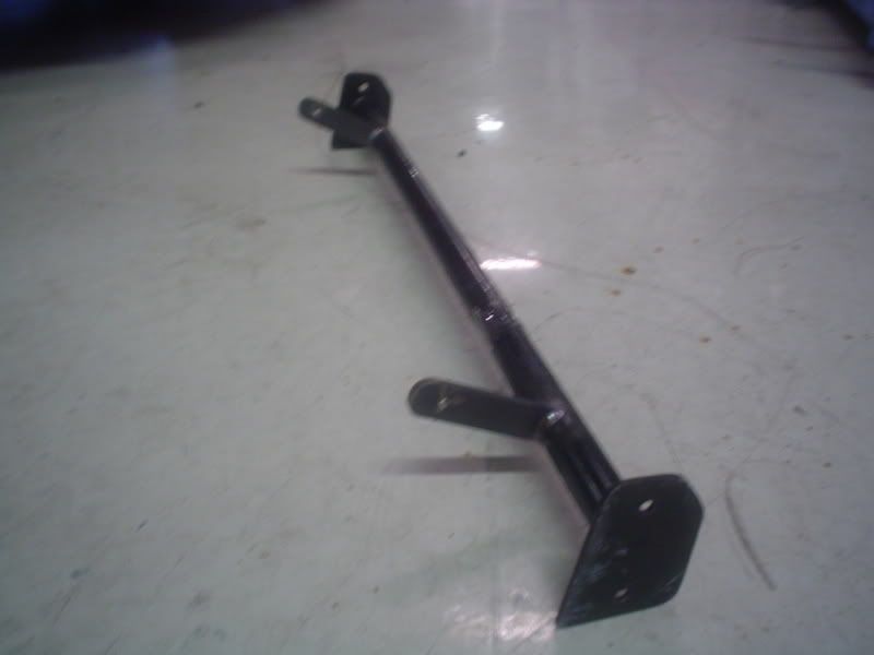
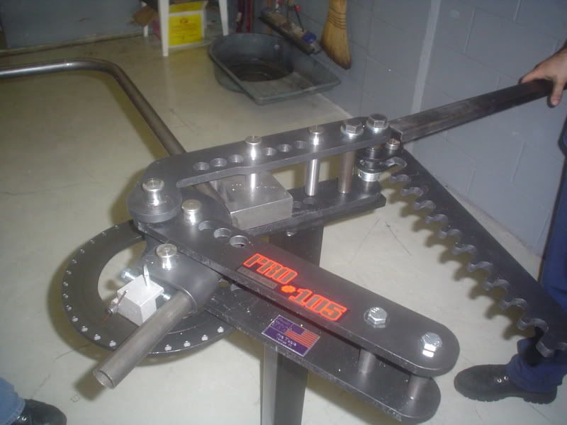
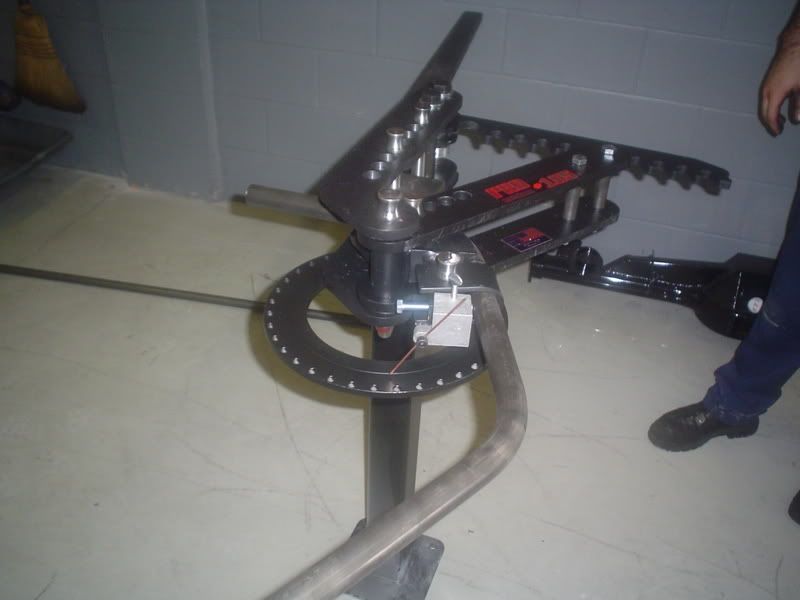
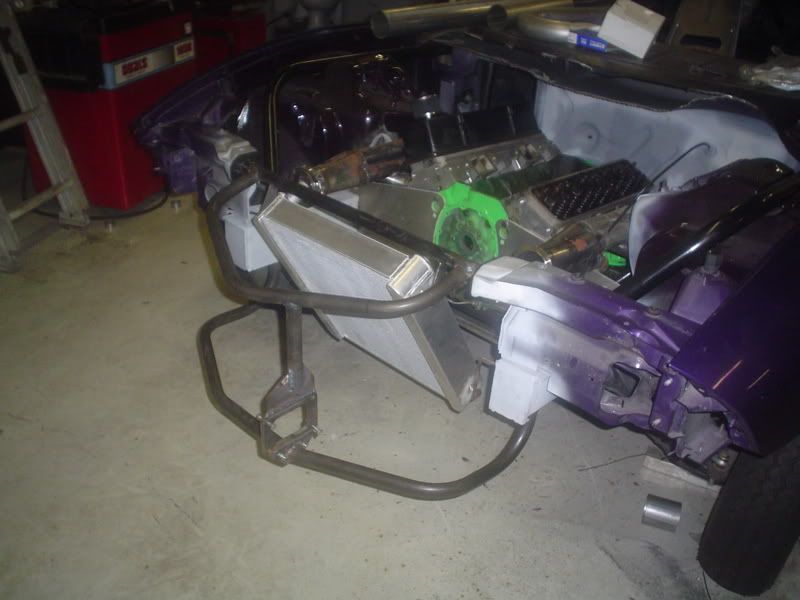
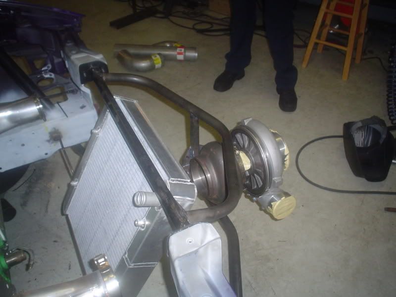
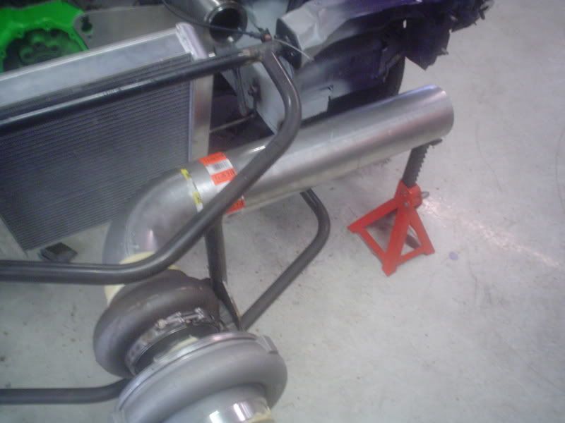
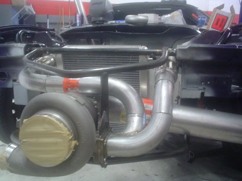
We had to get a little creative to mount this turbo. It needed to be supported because it's heavy and the exhaust system won't be strong enough to hold it up. We attempted to bend pipe with a Chinese made pipe bender. I then realized that China has never once made a worthwhile product in their life. So, I went down the road and bought a pipe bender made in the U.S.A. and it works awesome! Here's the bender bending our front support for the turbo, and the nose of the car...
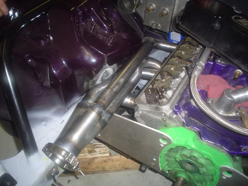
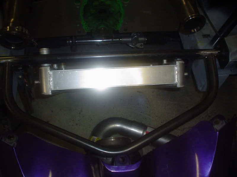
We then put a support in for the turbo and checked to see how it fit.
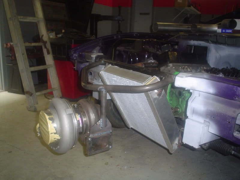
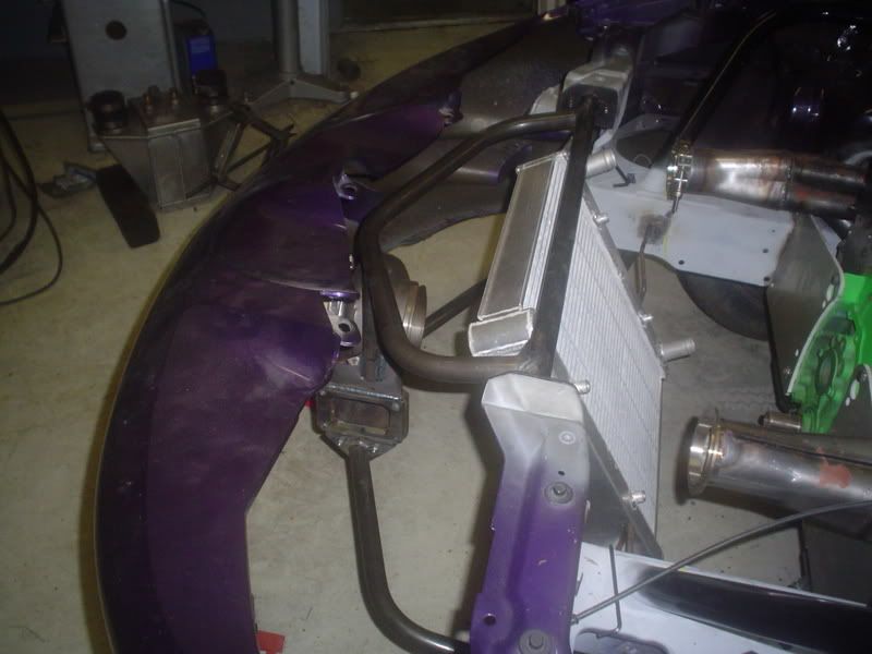
We then bent the lower supports and welded them in.
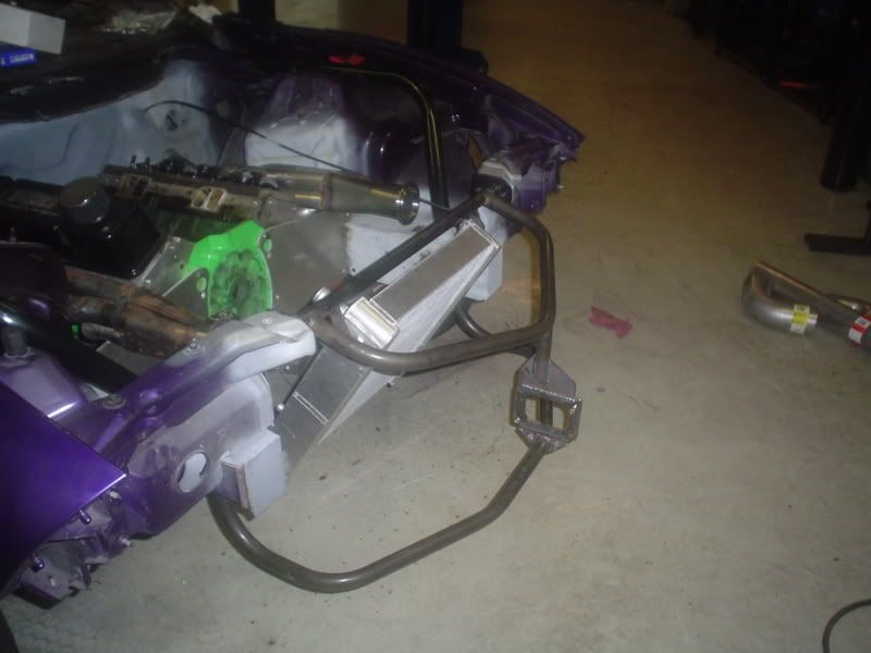
We then installed the turbo again to check for fit.
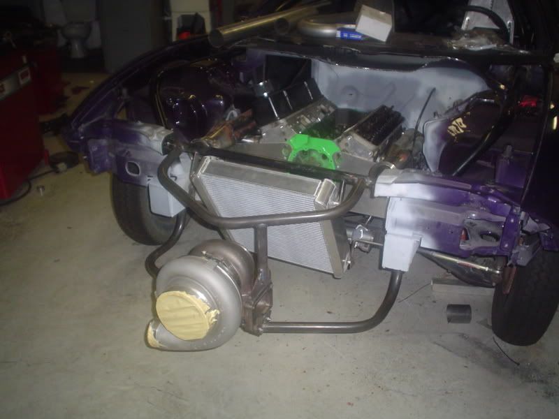
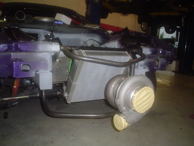
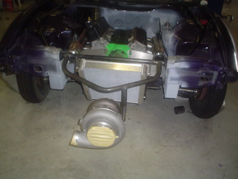
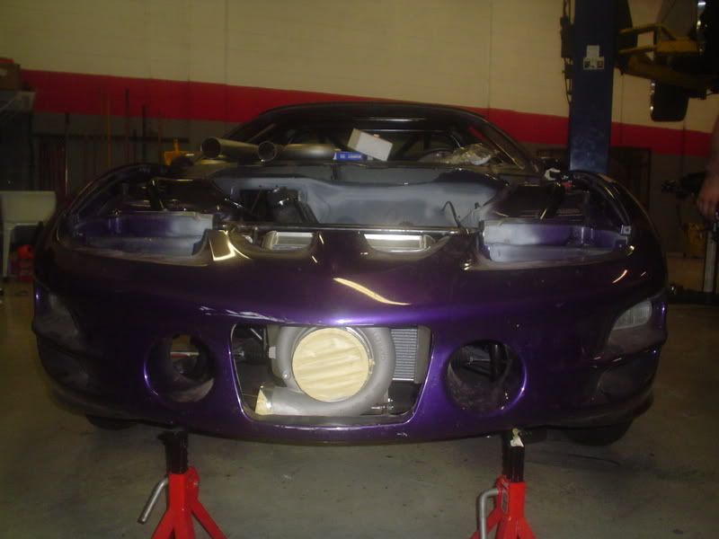
Then we put the nose back on to see how all that fit.

Next up, we'll be putting the downpipe in. It will be coming out the driver side in front of the front wheel. The machine shop called and the motor is almost ready for us. Can't wait!!
We had to get a little creative to mount this turbo. It needed to be supported because it's heavy and the exhaust system won't be strong enough to hold it up. We attempted to bend pipe with a Chinese made pipe bender. I then realized that China has never once made a worthwhile product in their life. So, I went down the road and bought a pipe bender made in the U.S.A. and it works awesome! Here's the bender bending our front support for the turbo, and the nose of the car...
We then put a support in for the turbo and checked to see how it fit.
We then bent the lower supports and welded them in.
We then installed the turbo again to check for fit.
Then we put the nose back on to see how all that fit.
Next up, we'll be putting the downpipe in. It will be coming out the driver side in front of the front wheel. The machine shop called and the motor is almost ready for us. Can't wait!!
07-16-2007, 09:52 PM
#69
TECH Resident
iTrader: (2)

Join Date: Oct 2006
Location: palmharbor/Clearwater,FL
Posts: 979
Likes: 0
Received 0 Likes
on
0 Posts
Nice bro....I gota come take a look soon. Oh and that vette fell threw it was beat to hell and it ended up being an auto. That toy store place blows.....
07-24-2007, 08:46 PM
#71
8 Second Club
Join Date: May 2002
Location: Toronto
Posts: 1,043
Likes: 0
Received 0 Likes
on
0 Posts

Are you serious about the 4l60e? I went 9.6@147 with my 700R4 last year and I thought I was pushing my luck... you want to go a second quicker! Can you get an SFI bell housing that will pass tech? I know I got lucky and managed to get my hands on one of the 20 JW Ultra Bell's that made for the 700R4's...
When do you think you will be ready to hit the track?
Good luck... I am very curious to hear how you make out!
When do you think you will be ready to hit the track?
Good luck... I am very curious to hear how you make out!
Originally Posted by DSG
Thanks guys. all the work is being done by Fernando at Tranmission Phycicians here in Tampa Florida. Fernando is doing 95% of the work while I help out here and there. Fernando is basically building every aspect of the car from the Chassis to the engine and even fabricating all the turbo piping. I mean everything.
His goal and mine also is to get the car to run 8.50's or better. The engine tranny combo is not LSX based. I am going to use a SBC and a 4l60e. We are trying to brake the 4l60e record and have the fastest A4 car in the world. Fernando is building me one heck of a car and its worth every penny. His work is top notch.
He can even paint. He is the one who panted the fenders and did the notching of the shock towers for the front bars of the roll cage.
I will make sure to update the thread with pics as we get work done.
07-25-2007, 01:48 PM
#72

Originally Posted by vmax1500
Are you serious about the 4l60e? I went 9.6@147 with my 700R4 last year and I thought I was pushing my luck... you want to go a second quicker! Can you get an SFI bell housing that will pass tech? I know I got lucky and managed to get my hands on one of the 20 JW Ultra Bell's that made for the 700R4's...
When do you think you will be ready to hit the track?
Good luck... I am very curious to hear how you make out!
When do you think you will be ready to hit the track?
Good luck... I am very curious to hear how you make out!
I think we're expecting to get her ready by the end of winter. Then we'll have to work out all the bugs. I don't expect the first runs to amount to much. We'll have a lot of tweaking to do.
07-27-2007, 10:28 AM
#73
10 Second Club
Thread Starter
iTrader: (1)
Join Date: Jul 2003
Location: St Petersburg, Fl
Posts: 568
Likes: 0
Received 0 Likes
on
0 Posts
UPDATE!
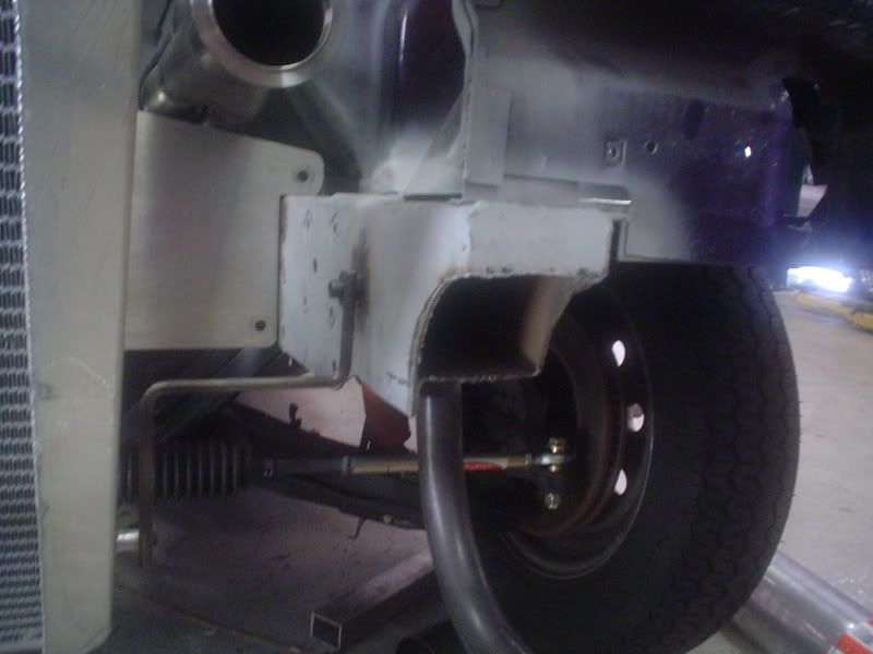
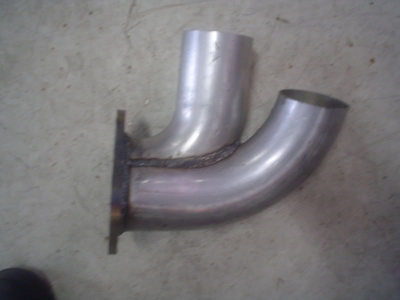
Looks like we've got all the hot piping done. We started out with the downpipe, which is really short and will exit through the bumper on the driver's side. It's a five inch downpipe and it didn't quite fit because the frame was in the way. Out came the plasma cutter and we cut it away. We'll do the finishing touches on that later.
Here's the downpipe "taped" in place.
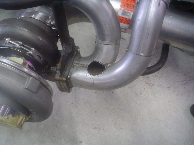
Then we made the section where the two pipes converge into the turbo flange.
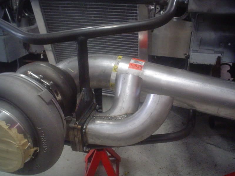
Then we piped up to the passenger header, followed by the driver header.
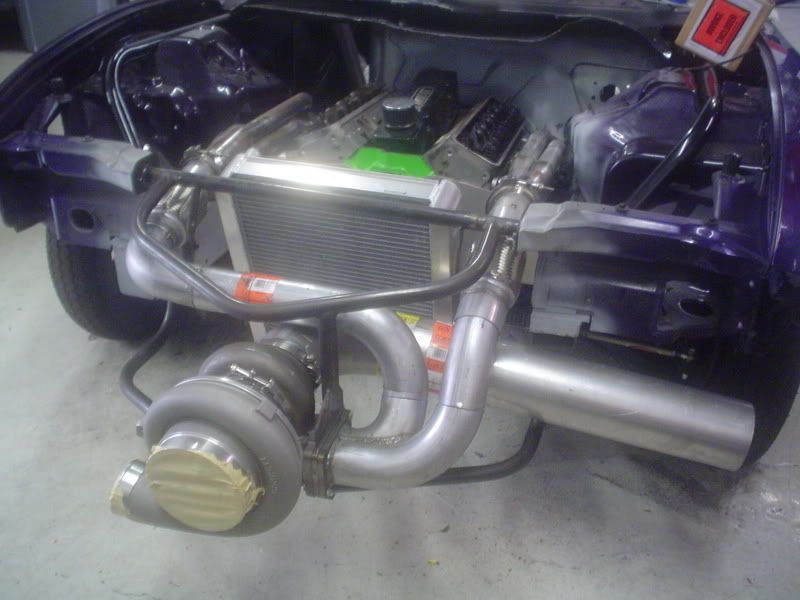
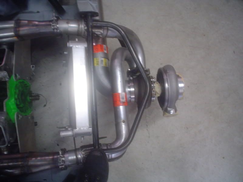
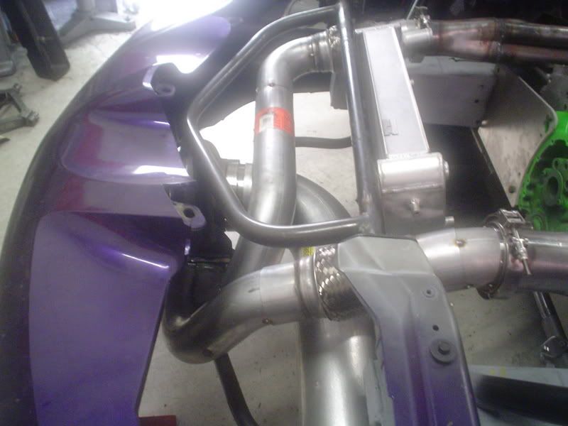
Next we're going to plumb in the wastegate. We might just get that done today. Moving right along...
Looks like we've got all the hot piping done. We started out with the downpipe, which is really short and will exit through the bumper on the driver's side. It's a five inch downpipe and it didn't quite fit because the frame was in the way. Out came the plasma cutter and we cut it away. We'll do the finishing touches on that later.
Here's the downpipe "taped" in place.
Then we made the section where the two pipes converge into the turbo flange.
Then we piped up to the passenger header, followed by the driver header.
Next we're going to plumb in the wastegate. We might just get that done today. Moving right along...

 07-27-2007, 02:17 PM
#78
10 Second Club
Thread Starter
iTrader: (1)
Join Date: Jul 2003
Location: St Petersburg, Fl
Posts: 568
Likes: 0
Received 0 Likes
on
0 Posts
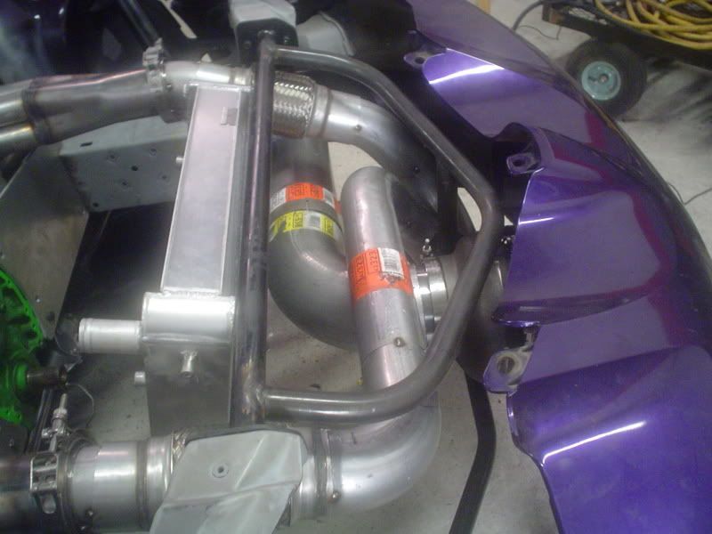
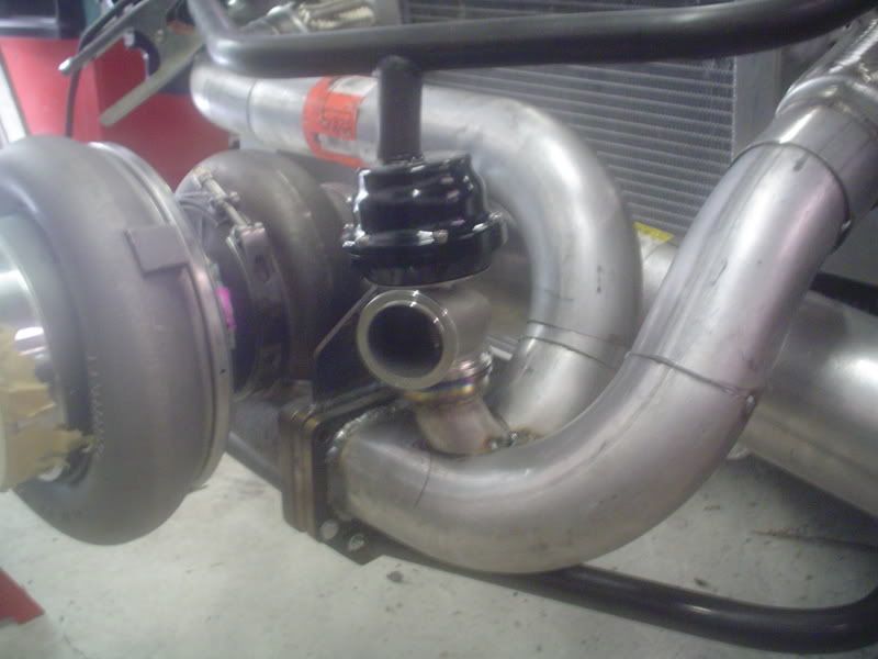
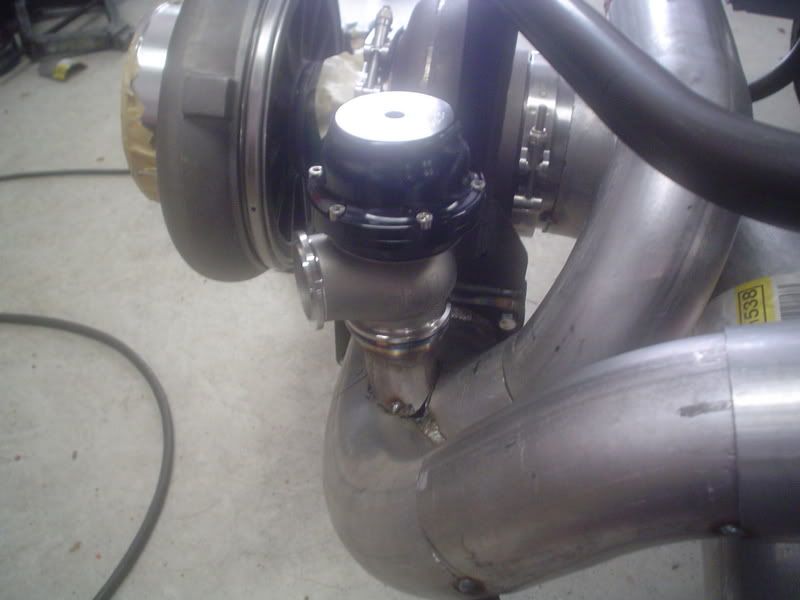
We cut a hole for the wastegate. It's a Tial 44mm which will be vented to atmosphere.
Here's a picture with the wastegate in place.
Everything has been removed for final welding. More to come.
Thanks for all the kind words guys. I promise to keep the pics comming as the project progresses.
Here's a picture with the wastegate in place.
Everything has been removed for final welding. More to come.
Thanks for all the kind words guys. I promise to keep the pics comming as the project progresses.
07-27-2007, 03:02 PM
#79

in the begining of this build, i thought you guys were ******* crazy. now, i have confirmed, you guys really ARE ******* crazy! lol. j/k. job looks professional and well thought out. thumbs up and i will head out there when i get some free time to check it out.
Fernando, at Transmission Physicans has done an incredible job!
Fernando, at Transmission Physicans has done an incredible job!