


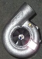

Just got in new 4" calibrated MAF ->

Thread Starter
TECH Addict
Joined: Nov 2001
Posts: 2,207
Likes: 0
From: College Station, Tx
 Just got in new 4" calibrated MAF ->
 Which should be able to meter all the air my s-trim can pump out - it's a PRO-M 4" Univer, and I have a calibration for it up to 800 g/sec at about 10.5 kHz. (Have exact values of course - it calibrated out very nicely).


Just need to do the divided by two trick and I should be able to meter all the air - negating the need for any PE vs RPM trickery. Plus I don't think the meter will be a restriction . The holes are actually sampling orifices which go to a vaned tunnel until they get to the sensor - so it doesn't make a large difference what is before the maf (90, straight pipe, filter, etc.) as it does a good job at internal smoothing.
Coupled with LJ's Acceleronics box I think this will allow the stock computer to cope with boost very well - plus MAF is 1000x easier to tune than SD (and much more accurate).
Chris
Just need to do the divided by two trick and I should be able to meter all the air - negating the need for any PE vs RPM trickery. Plus I don't think the meter will be a restriction
. The holes are actually sampling orifices which go to a vaned tunnel until they get to the sensor - so it doesn't make a large difference what is before the maf (90, straight pipe, filter, etc.) as it does a good job at internal smoothing. Coupled with LJ's Acceleronics box I think this will allow the stock computer to cope with boost very well - plus MAF is 1000x easier to tune than SD (and much more accurate).
Chris

TECH Fanatic
Joined: Mar 2002
Posts: 1,452
Likes: 0
From: toronto
Re: Just got in new 4 So when's the ChrisB maff-tastic special going to start ?
Have you had it on the car yet ?
reason i ask is I'm having all kinds of maff issues set a p101 code and the maff is jumping all over the place and can't figure out why
Have you had it on the car yet ?
reason i ask is I'm having all kinds of maff issues set a p101 code and the maff is jumping all over the place and can't figure out why
Thread Starter
TECH Addict
Joined: Nov 2001
Posts: 2,207
Likes: 0
From: College Station, Tx
Re: Just got in new 4 No, it outputs a 0-5V signal, I built a little converter to swap it over
http://www.slowcar.net/MAF%20Circuit.jpg
from that design I just added a few small caps on the outputs of the Voltage regulators basically. You can use the potentiometer to skew it for ls1 frequency output range easily. Then you just need a voltmeter, power supply, and frequency counter (my DVM did this, plus checked it on a oscilloscope) to determine the voltage vs. frequency function. From pro-m you can get a calibration of flow vs. voltage - then you just swap it over.
The meter retail is about 350 I think. Pro-m also makes a converter box, but it was a bit pricey (250ish I think) - but if you get theirs they will take care of the frequency output calibration and just give you airflow vs. frequency. But then even with a pcb made the circuit above was like 30 bucks in parts.
http://www.slowcar.net/MAF%20Circuit.jpg
from that design I just added a few small caps on the outputs of the Voltage regulators basically. You can use the potentiometer to skew it for ls1 frequency output range easily. Then you just need a voltmeter, power supply, and frequency counter (my DVM did this, plus checked it on a oscilloscope) to determine the voltage vs. frequency function. From pro-m you can get a calibration of flow vs. voltage - then you just swap it over.
The meter retail is about 350 I think. Pro-m also makes a converter box, but it was a bit pricey (250ish I think) - but if you get theirs they will take care of the frequency output calibration and just give you airflow vs. frequency. But then even with a pcb made the circuit above was like 30 bucks in parts.
Re: Just got in new 4 I had a similar MAF on mine before, 3.5" though.
Worked out nicely. My only warning is temperature shift on your V to F. Watch very carefully for it.
I had Pro-M box, it took a ****, i'm not using the Univer or box anymore
It does work though.
Worked out nicely. My only warning is temperature shift on your V to F. Watch very carefully for it.
I had Pro-M box, it took a ****, i'm not using the Univer or box anymore
It does work though.
Re: Just got in new 4
No, it outputs a 0-5V signal, I built a little converter to swap it over
http://www.slowcar.net/MAF%20Circuit.jpg
from that design I just added a few small caps on the outputs of the Voltage regulators basically. You can use the potentiometer to skew it for ls1 frequency output range easily. Then you just need a voltmeter, power supply, and frequency counter (my DVM did this, plus checked it on a oscilloscope) to determine the voltage vs. frequency function. From pro-m you can get a calibration of flow vs. voltage - then you just swap it over.
The meter retail is about 350 I think. Pro-m also makes a converter box, but it was a bit pricey (250ish I think) - but if you get theirs they will take care of the frequency output calibration and just give you airflow vs. frequency. But then even with a pcb made the circuit above was like 30 bucks in parts.
http://www.slowcar.net/MAF%20Circuit.jpg
from that design I just added a few small caps on the outputs of the Voltage regulators basically. You can use the potentiometer to skew it for ls1 frequency output range easily. Then you just need a voltmeter, power supply, and frequency counter (my DVM did this, plus checked it on a oscilloscope) to determine the voltage vs. frequency function. From pro-m you can get a calibration of flow vs. voltage - then you just swap it over.
The meter retail is about 350 I think. Pro-m also makes a converter box, but it was a bit pricey (250ish I think) - but if you get theirs they will take care of the frequency output calibration and just give you airflow vs. frequency. But then even with a pcb made the circuit above was like 30 bucks in parts.
then ls1edit to rescale?
is that right, so your looking at $380 or $600?

Moderator

Joined: Nov 2001
Posts: 3,048
Likes: 12
From: Raleigh, NC
Re: Just got in new 4 Chris, you are an f'ing GENIUS! 
I hope to see you as the billionaire engineering mogul one day on the cover of Times magazine.
Anyway... I could see an 800 g/sec MAF as being a definite help to me. Please keep us aprised.
I hope to see you as the billionaire engineering mogul one day on the cover of Times magazine.
Anyway... I could see an 800 g/sec MAF as being a definite help to me. Please keep us aprised.
Trending Topics
Thread Starter
TECH Addict
Joined: Nov 2001
Posts: 2,207
Likes: 0
From: College Station, Tx
Re: Just got in new 4 Harlan: Yep, your old setup is what originally gave me the idea for it Thanks for the heads up on the temp variance - I will check that out, and if it's too high I might just swap over to a pic to do the sampling and conversion with. The LM131 is used for the F-V is a military/aerospace part that is *supposto* be fine for the temps the box will see, but I will check it out!
smokinHawk: Yep, that's pretty much it. I think the 350 is retail on the maf - I paid a bit less than that, but I don't know what it generally goes for. 350 was msrp I think, so it should be that for sure, or less.
Black LS1: Thanks, but I have to give Harlan credit for the original idea of using the maf. I'll definitely let you all know how it works out!
The nice thing is on a LS1, if you do the 1/2x airflow trick, the timing tables will now actually scale up to 2x what the say - so 1.4 g/sec would actually be 2.8 g/sec, etc. - so you can effectively scale timing by "boost", or at least airflow/load (which is what you want to do anyway).
Thanks for the heads up on the temp variance - I will check that out, and if it's too high I might just swap over to a pic to do the sampling and conversion with. The LM131 is used for the F-V is a military/aerospace part that is *supposto* be fine for the temps the box will see, but I will check it out!smokinHawk: Yep, that's pretty much it. I think the 350 is retail on the maf - I paid a bit less than that, but I don't know what it generally goes for. 350 was msrp I think, so it should be that for sure, or less.
Black LS1: Thanks, but I have to give Harlan credit for the original idea of using the maf. I'll definitely let you all know how it works out!
The nice thing is on a LS1, if you do the 1/2x airflow trick, the timing tables will now actually scale up to 2x what the say - so 1.4 g/sec would actually be 2.8 g/sec, etc. - so you can effectively scale timing by "boost", or at least airflow/load (which is what you want to do anyway).
LS1 Tech Stories
The Best V8 Stories One Small Block at Time

Gas Monkey Built a 6-Wheel Ferrari Testarossa With a Corvette LT4 Engine
Verdad Gallardo
7 Most Reliable High-Performance Engines GM Has Ever Built
Verdad Gallardo
Amazing '71 Camaro Restomod Is Modern Muscle Car Under the Skin
Verdad Gallardo
6 Common C5 Corvette Failures and What's Involved In Repairing Them
Pouria Savadkouei
Retro Modern Bandit Pontiac Trans AM Comes With Burt Reynolds' Autograph
Verdad Gallardo
Top 10 Greatest Cadillac V Series Performance Models Ever, Ranked
Pouria Savadkouei
Top 10 Most Powerful Chevy Trucks Ever Made!

Hennessey's New Supercharged Silverado ZR2 Has 700 HP
Verdad Gallardo
Coachbuilt N2A Anteros Is an LS2-Powered C6 Corvette In Italian Clothes
Verdad Gallardo Re: Just got in new 4 definatly keep us up to date with this ill need a new MAF solution soon, and i dont want to pay 2-3grand for a FAST system.
id love to be running 20psi safely.
id love to be running 20psi safely.


