


Will I notice a difference between 3" and 4" intercooler piping?
All i was after was someone to give me some CFM numbers for the pipes using PV=NRT and asuming you have a maximum air speed of 250ft per second @ 20psi......(cant rember the veriables)
sorry if i didn't make that clear.
the reason i ask is i know STS guys have problems with the piping they run once they push past about 700rwhp. now if we know that a 3.0inch pipe can support say 125lbs of air per min then you know you can run a 3.0 inch pipe on a 1000bhp setup.
basically just trying to understand at what point, BHP wise, you need to run bigger piping.
Cheers
Chris.
Thats what i mean a there no standed for pipe flow in a engine to = hp. A 1 foot 3inch pipe might flow 300 lbs of air but the same 3 inch pipe that 15 feet long might only flow 150lbs. Now take the 15 foot long pipe and flow 200 degree air though it might only flow 100 lbs now
When you get into boost the cfm flow changes ever thing raw flow numbers mean alot less a 2.5 inch pipe car in FL might only make 600 hp but same car in canada on a cold day might flow enough for 800hp. The flow of the pipe stays the same but the density of the air changed
Can it be figure out YES but you need every last spec and detail. then you have to pay some one to sit there for a few hours to mock it out.
ME degree in a good college is about 65 grand
Last edited by BigRich954RR; Apr 1, 2009 at 07:33 PM.

TECH Addict
Joined: Aug 2004
Posts: 2,866
Likes: 4
Thats what i mean a there no standed for pipe flow in a engine to = hp. A 1 foot 3inch pipe might flow 300 lbs of air but the same 3 inch pipe that 15 feet long might only flow 150lbs. Now take the 15 foot long pipe and flow 200 degree air though it might only flow 100 lbs now
When you get into boost the cfm flow changes ever thing raw flow numbers mean alot less a 2.5 inch pipe car in FL might only make 600 hp but same car in canada on a cold day might flow enough for 800hp. The flow of the pipe stays the same but the density of the air changed
Can it be figure out YES but you need every last spec and detail. then you have to pay some one to sit there for a few hours to mock it out.
ME degree in a good college is about 65 grand
Just wondered if it was like exhaust though where they say oh for xxxbhp you need a 'something' inch exhaust. if thats not the case for the intake then no worries.
Chris.
TECH Addict
Joined: Aug 2004
Posts: 2,866
Likes: 4

i cant rember the guys but it was on one of longrange4u's threads. He was talking about how restrictive the stock STS pipe work was on the cole side. Someone said you want to keep air speed below 250 feet per second as thats when you start to encounter problems. I think Zombie for longrange did some calcs and figured they where nearly in the 400 feet per second range!!!
Chris.
Thread Starter
TECH Enthusiast
iTrader: (4)
Joined: Dec 2005
Posts: 612
Likes: 0
From: Nashville, TN
Feet per second mate!
i cant rember the guys but it was on one of longrange4u's threads. He was talking about how restrictive the stock STS pipe work was on the cole side. Someone said you want to keep air speed below 250 feet per second as thats when you start to encounter problems. I think Zombie for longrange did some calcs and figured they where nearly in the 400 feet per second range!!!
Chris.
At 400fps your looking at 1178cfm through a 3" and a 4" is at 2094cfm.
If your feeding lets say a 408 your looking at needing about 1500cfm at atmospheric pressure spinning to 6800rpms. So on a 3" setup your going to have to push past 400fps to about 534fps.... Thats moving some friggin air but thats only if you can overcome the headloss though the 3" pipe.. Your looking at about 660in.wc/100' head loss
Last edited by Tricked-Out-Toy; Apr 2, 2009 at 11:58 AM.
TECH Addict
Joined: Aug 2004
Posts: 2,866
Likes: 4
Reading comp owns me.... Thats a big difference lol. 250fps is 15000fpm. At 15K fpm your looking at 736.3cfm through a 3" pipe and through a 4" your looking at 1308.9cfm.
At 400fps your looking at 1178cfm through a 3" and a 4" is at 2094cfm.
If your feeding lets say a 408 your looking at needing about 1500cfm at atmospheric pressure spinning to 6800rpms. So on a 3" setup your going to have to push past 400fps to about 534fps.... Thats moving some friggin air but thats only if you can overcome the headloss though the 3" pipe.. Your looking at about 660in.wc/100' head loss
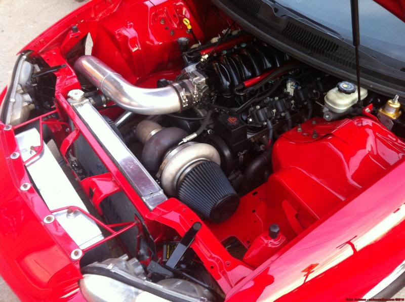
i have 3 " now... 402ci l92 heads and A F1A with 3.7 pulley..
i have 25 psi on the hot side of my CXRacing intercooler and only 15psi at the engine... thats a 10 psi drop... ive got to do something..
my d1sc with 3.4 pulley made 13psi and 676rwhp through a 4l80e
my F1A with 3.7 pulley made 15 psi and 700rwhp through a 4l80e
Both pulleyed to the max.... im thinking bout my options now
9 Second Club


Joined: Oct 2006
Posts: 1,194
Likes: 249
From: IL
We changed from 3.5" to 4", but haven't run the car yet. The piping setup on the car is 3" out of the turbo (76mm turbo), transition to 3.5", silicone adapter from 3.5" to 4", intercooler is 4" in and out to make it "future proof", 4" from the intercooler to the throttle body where there is a 4" to 4.5" silicone adapter.
Obviously we don't for see any downside to the layout, and the main reason for it is for a future larger turbo. If the turbo is 3.5" or 4" outlet, all of the piping (save for a small section) is already in place. It also looks better with the massive throttle body to have a pipe that is close to the same size. Working with 4" tube is a pain in the *** though, so much more welding!
Sean
LS1 Tech Stories
The Best V8 Stories One Small Block at Time

Topdon ONE vs. Artidiag 800 BT2: Which is the Diagnostic Tablet For You?
Pouria Savadkouei
Gas Monkey Built a 6-Wheel Ferrari Testarossa With a Corvette LT4 Engine
Verdad Gallardo
7 Most Reliable High-Performance Engines GM Has Ever Built
Verdad Gallardo
Amazing '71 Camaro Restomod Is Modern Muscle Car Under the Skin
Verdad Gallardo
6 Common C5 Corvette Failures and What's Involved In Repairing Them
Pouria Savadkouei
Retro Modern Bandit Pontiac Trans AM Comes With Burt Reynolds' Autograph
Verdad Gallardo
Top 10 Greatest Cadillac V Series Performance Models Ever, Ranked
Pouria Savadkouei
Top 10 Most Powerful Chevy Trucks Ever Made!

Hennessey's New Supercharged Silverado ZR2 Has 700 HP
Verdad Gallardo
On The Tree
Joined: Jun 2010
Posts: 120
Likes: 2
theoretically to reduce pressure drop that comes from the pipe restriction. even if your TB is smaller. but the question is how much ? is it worth it ? .
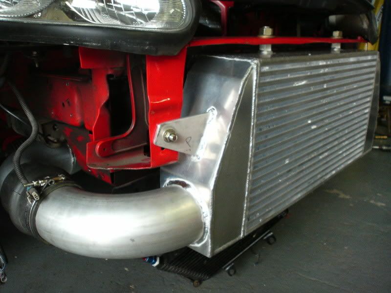
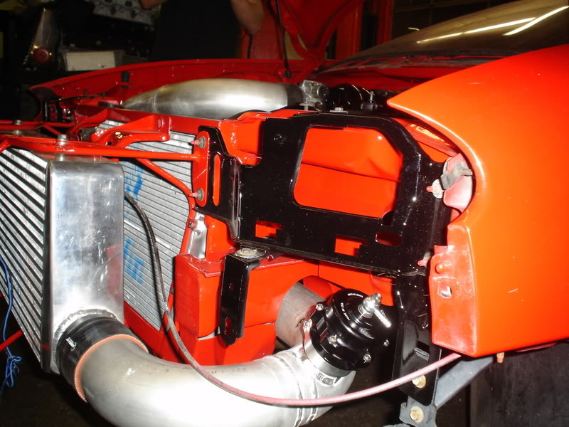
What intercooler is that one? Were you find it?
I've debated doing this on my car.
The air has to really bake through a 3" section at 700 HP. Probably between 400 and 600 fps.
We've got some fancy modeling software at work and I was showing at those flow rates, you can induce a between 1 and 2 psi pressure drop over just a few feet of piping. It really boils down to your bends and piping length. Its modeling software so take it or leave it.
I think going to 4" you may be able to get a little more out of a specific turbo, but I don't think it is going to make much of a difference - so you add a smidge more in back-pressure - no biggie.
I think this is a better mod for the S/C guys with a fixed impeller speed or folks expecting to move much higher in HP.
TECH Addict
Joined: Aug 2004
Posts: 2,866
Likes: 4
NoGo, some intresting maths here on dynamic flow rates and what size piping is needed to minimise restriction.... (half way down post by user Max_Torque).
http://www.pistonheads.com/gassing/t...tion&mid=36792
Chris.
http://www.pistonheads.com/gassing/t...tion&mid=36792
Chris.
Also, the way he does it isn't applicable if you have a turbo or supercharger on the car.
To figure out charge speed:
Engine Flow Naturally Aspirated = (((Cu In/1728) * RPM) / 2) * Volumetric Efficiency
so for my engine...
Engine Flow Naturally Aspirated = (((383 / 1728) * 6400) / 2) * 0.85
Engine Flow Naturally Aspirated = 602 CFM
Engine Flow Boosted = (Boost+14.67)/14.67 * Engine Flow Naturally Aspirated
so for my engine...
Engine Flow Boosted = (17 psi + 14.67 psi)/14.67 * 602 CFM
Engine Flow Boosted = 1299 CFM....about out of room with the D1
To figure pipe velocity:
Pipe Velocity = (Engine Flow Boosted / ((((Pipe Diameter^2)/4 * 3.14))/144))/60
so for my engine....
Pipe Velocity = (1299 CFM / ((((3in ^2)/4 * 3.14))/144)/60
Pipe Velocity = 441 fps
In an ideal world I would try and keep pipe velocities to no more than 100 fps. Above 100 fps you start to get out of the valley of the curve and head up the non-linear portion for pressure drop. However, I don't think this is very realistic in our world of 600+ HP.
I think going through the above math and adjusting your inlet piping accordingly makes sense for N/A application. I don't think it is realistic for most supercharger applications and I'm sure it is just splitting hairs with a turbo - so you spin your turbo a smidge faster....no biggie.
JMO.
This thread....
http://speedtalk.com/forum/viewtopic...r+pipe#p347197
http://speedtalk.com/forum/viewtopic...r+pipe#p347197

I have nothing to add to this as far as insight, but the 4" sure looks cool! 
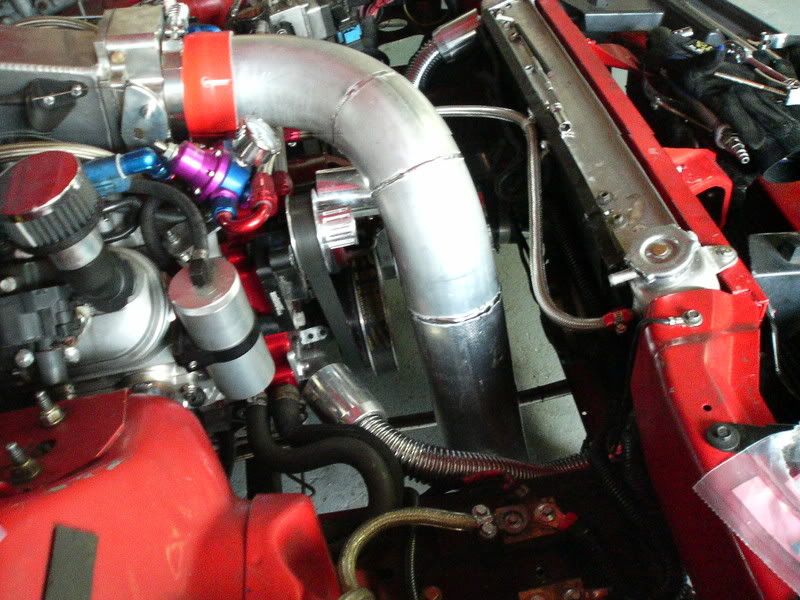
I have 3.5" from my turbo to the IC, and a 4" from the IC to the Throttle body.
edit, the 4" matches right up and I have a stock TB. I have a 4" coupler that fits perfect.
couple old pics from fabbing it and stuff

I have 3.5" from my turbo to the IC, and a 4" from the IC to the Throttle body.
edit, the 4" matches right up and I have a stock TB. I have a 4" coupler that fits perfect.
couple old pics from fabbing it and stuff
Last edited by SS4Matt; May 12, 2012 at 08:24 PM.
Above inter cooler bracket, best I've seen...
This is the answer to the much debated question, as to, whats the rite diameter for the charge pipe, The same diameter of the throttle body, is the correct answer.
This is the answer to the much debated question, as to, whats the rite diameter for the charge pipe, The same diameter of the throttle body, is the correct answer.
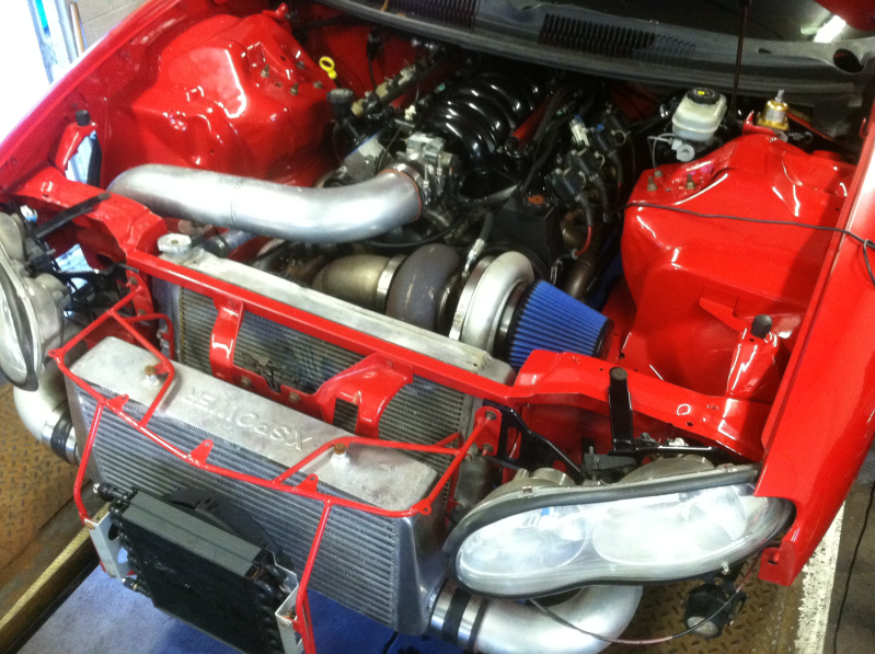
thanks! a few chassis tabs, about 20 feet of 1/4" chromoly round bar and a few evenings and a couple beers. The radiator is mounted and floating in the core support by that as well as the trans cooler.
i have two 2.5" piping coming from the turbos to my two intercoolers then two 3" pipes merged into one pipe into the throttle body. i would think the bigger the pipe the more leg you would have.