
How to Microsquirt fuel and spark your LSX swap (sloppy mechanics how to!) 8-10-13
 01-25-2013, 12:15 PM
#41
TECH Apprentice

Also @ alkyman, if you update to the Beta release of Tunerstudio it can do smoothing.
 01-25-2013, 01:18 PM
#42


Question - You currently aren't using any fast idle control during cold start, correct?
Do you add timing when the idle drops to a certain rpm to increase idle speed? Similar to what this talks about?
http://www.diyautotune.com/tech_arti...le_tuning.html
Doug
Do you add timing when the idle drops to a certain rpm to increase idle speed? Similar to what this talks about?
http://www.diyautotune.com/tech_arti...le_tuning.html
Doug
01-25-2013, 01:22 PM
#43

yes the lower part of the timing map below idle is higher than the regular idle amount of timing and i also add in a little timing when the motor is cold to hold the rpm up a little bit
the timing at the bottom of the map helps it from dying off if you chop the throttle like on a burnout or quick rev, when it comes down and wants to settle at 20deg at 900rpm and drops to 400-500 25-28 in there will help it from dropping off
the timing at the bottom of the map helps it from dying off if you chop the throttle like on a burnout or quick rev, when it comes down and wants to settle at 20deg at 900rpm and drops to 400-500 25-28 in there will help it from dropping off
01-25-2013, 01:35 PM
#44
Ok thanks for the tip.
I am not sure how I want to proceed when I get my motor going. I'm still kicking around using Megasquirt, microsquirt, or HPtuners. I don't plan to start up with AC, but I may want to add it at a later date. It seems if I want to do that I may have to use megasquirt. I am trying to determine if I can somehow trigger a fast idle solenoid off a switch or something and still use something small like the microsquirt. I'm sure it shouldn't take more than a switch and a relay.
Doug

 02-15-2013, 09:11 PM
#50
TECH Regular
iTrader: (2)
Join Date: Dec 2009
Location: Austin Texas
Posts: 414
Likes: 0
Received 0 Likes
on
0 Posts
Just want to add a couple tips should you go with a Microsquirt-
1. Be very careful when you solder the resistors on the back of the board- it is very easy to apply too much heat to the solder joint and do damage to the other side of the board
2. If you use the Autozone Fuse Panel Denmah recommends, be sure and check the power output sides occasionaly or inspect the back for bad connections.
I had these 2 problems and luckly the folks at EFI Source are great people to deal with and they fixed my Microsquirt very quickly. The first fuse panel that I got was a POS, had some defects in the assembly. I got another one and it seems to be fine but I think Im still going to get something else.
02-15-2013, 10:27 PM
#51
yes great tips, i have never had a problem with one of these fuse panels i feel bad you did haha cuz i recommend them!
and yeah whenver soldering any ms product be super careful, if you cant get it soldered the way you want in like 1-2 seconds quit and let it cool down and try again.
that goes with nearly any electronic component
thanks for keeping this thread going!
i know there are some people running it now and i would love for them to post up results!
02-16-2013, 12:03 PM
#53
TECH Apprentice
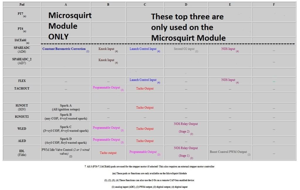
The label in the leftmost column can do anything in that row, but only one of those things can be assigned to that pin at a time. That is the short answer.
But,I made that for the guys on the MSextra board that are more familiar with the way the Input/Output charts have been done over there. It is just a modified version of what the is in the MegaManual.(That can be hard to read sometimes)
Here is a link to what they changed the manual to for use with the Microsquirt.(basically they polished up what I did quickly)
Click here and scroll down to the Microsquirt table.
http://www.msextra.com/doc/ms2extra/...htm#ms2options
The inputs and outputs, are few on the Microsquirt once we use it to fire a V8 Coil on Plug. We start with 4 outputs and three inputs, then we use up two outputs for the extra coils of the V8 engine. This leaves us with just two outputs, and three inputs.
This is how I see the Inputs and Outputs being used.(This is more what people are needing to see, I think.)
Pin 29(orange/green) --in-- Second o2 sensor, or Launch Control input (spare ADC input one pin)
Pin 5 (pink/purple) --in-- Fuel pressure input or any 0 to 5 volt input (spare ADC input two pin)
Pin 6 (purple/white) --in-- Lauch Control input or Flex fuel sensor input (Flex input pin)
Pin 7 (green ) -out- Boost Control output, or programmable out (Fast Idle Output pin)
Pin 35(green/yellow) -out- Tach output or programmable output (Tach output pin)
Pin 8(purple) -out- This can ONLY be programmed for the fuel pump out, but I also like to use it to turn on the electric fan,or Fan Low(Fuel pump output)
Hope that clears somethings up alittle.
02-16-2013, 12:25 PM
#54
On The Tree

The label in the leftmost column can do anything in that row, but only one of those things can be assigned to that pin at a time. That is the short answer.
But,I made that for the guys on the MSextra board that are more familiar with the way the Input/Output charts have been done over there. It is just a modified version of what the is in the MegaManual.(That can be hard to read sometimes)
Here is a link to what they changed the manual to for use with the Microsquirt.(basically they polished up what I did quickly)
Click here and scroll down to the Microsquirt table.
http://www.msextra.com/doc/ms2extra/...htm#ms2options
The inputs and outputs, are few on the Microsquirt once we use it to fire a V8 Coil on Plug. We start with 4 outputs and three inputs, then we use up two outputs for the extra coils of the V8 engine. This leaves us with just two outputs, and three inputs.
This is how I see the Inputs and Outputs being used.(This is more what people are needing to see, I think.)
Pin 29(orange/green) --in-- Second o2 sensor, or Launch Control input (spare ADC input one pin)
Pin 5 (pink/purple) --in-- Fuel pressure input or any 0 to 5 volt input (spare ADC input two pin)
Pin 6 (purple/white) --in-- Lauch Control input or Flex fuel sensor input (Flex input pin)
Pin 7 (green ) -out- Boost Control output, or programmable out (Fast Idle Output pin)
Pin 35(green/yellow) -out- Tach output or programmable output (Tach output pin)
Pin 8(purple) -out- This can ONLY be programmed for the fuel pump out, but I also like to use it to turn on the electric fan,or Fan Low(Fuel pump output)
Hope that clears somethings up alittle.
But,I made that for the guys on the MSextra board that are more familiar with the way the Input/Output charts have been done over there. It is just a modified version of what the is in the MegaManual.(That can be hard to read sometimes)
Here is a link to what they changed the manual to for use with the Microsquirt.(basically they polished up what I did quickly)
Click here and scroll down to the Microsquirt table.
http://www.msextra.com/doc/ms2extra/...htm#ms2options
The inputs and outputs, are few on the Microsquirt once we use it to fire a V8 Coil on Plug. We start with 4 outputs and three inputs, then we use up two outputs for the extra coils of the V8 engine. This leaves us with just two outputs, and three inputs.
This is how I see the Inputs and Outputs being used.(This is more what people are needing to see, I think.)
Pin 29(orange/green) --in-- Second o2 sensor, or Launch Control input (spare ADC input one pin)
Pin 5 (pink/purple) --in-- Fuel pressure input or any 0 to 5 volt input (spare ADC input two pin)
Pin 6 (purple/white) --in-- Lauch Control input or Flex fuel sensor input (Flex input pin)
Pin 7 (green ) -out- Boost Control output, or programmable out (Fast Idle Output pin)
Pin 35(green/yellow) -out- Tach output or programmable output (Tach output pin)
Pin 8(purple) -out- This can ONLY be programmed for the fuel pump out, but I also like to use it to turn on the electric fan,or Fan Low(Fuel pump output)
Hope that clears somethings up alittle.
03-01-2013, 05:46 AM
#57
Plz don't use a battery charger to power the micro. It is not regulated at all. The reason you had difficulties flashing it using The 2 amp setting is that the voltage varied below the lower threshold limit. This can lead to a corrupt flash process. I recommend using a battery with a constant output, I.e. lawn mower, atv battery or a wall wart power supply that has 1 amp capability. It does not need a ton of current but does require a stable power supply. The variations in supply voltages can be seen by data logging with tuner studio and viewing the ripple.
03-01-2013, 11:20 AM
#60
TECH Apprentice
Great video, matt.
A small battery to absorb the ripple off of that charger would be a good idea.
You can kind of see in the video what the ripple is doing to the TPS signal, at zero it keeps bouncing around.
This video will help alot those wanting to do this install, themselves, but are a little lost on the loading of firmware.
And I am glad you showed that once the Extra firmware is in the Microsquirt, the boot loader wire, is not used again, unless there is some kind of corruption in the firmware, and the Laptop,and ECU won't communicate.