
Out of curiousity why does everyone use 2.5" on the crossover pipe
 12-10-2013 | 03:21 PM
#221
12-10-2013 | 03:54 PM
#222

So in my case I already have a 2.5� system that�s done. Any real benefit to redoing the whole hotside VS just dropping the exhaust down at the flange? This is an auto drag car I launch off the Trans-brake. Sure would be a lot easier to run what I have!
12-10-2013 | 04:36 PM
#223
Just leave it alone it will work great. How is your spool up time on the brake?
12-10-2013 | 09:26 PM
#224
My spool up wasn't that great honestly. And boost did not build as quickly as I would have liked. I'd see full boost (24lbs) around 4800rpm rolling into it in high gear. Going with a new cam, more compression and a 2.125 hotside of some sort this time around. Old setup was a 5.3 @ 8.6:1 compression and zr1 cam. I'd like to try necking it down at the flange VS redoing all the piping and vbands. If there is a valid reason to redo the whole hotside I will do it.
12-10-2013 | 10:51 PM
#225

the hole reason why this works is that you never let the exhaust gases expand in front of the turbo keeping the velocity up going in to the wheel. if you let the hot gas expand then pack it in to a smaller space you slow it down.
12-11-2013 | 06:54 AM
#226
You would get a venturi effect. and sacrifice pressure for velocity?

I was thinking of it like a rocket engine. They use a cone at the end to increase velocity, they don't use a straight run of small diameter pipe for a long length. They use something like this...

http://en.wikipedia.org/wiki/De_Laval_nozzle
Last edited by Forcefed86; 12-11-2013 at 07:41 AM.
12-11-2013 | 07:21 AM
#227
My spool up wasn't that great honestly. And boost did not build as quickly as I would have liked. I'd see full boost (24lbs) around 4800rpm rolling into it in high gear. Going with a new cam, more compression and a 2.125 hotside of some sort this time around. Old setup was a 5.3 @ 8.6:1 compression and zr1 cam. I'd like to try necking it down at the flange VS redoing all the piping and vbands. If there is a valid reason to redo the whole hotside I will do it.
12-13-2013 | 04:46 PM
#228
necking it down doesn't help because that's what's already happening with the hot side you have now as exhaust is getting packed in to your turbo.
 01-24-2014 | 08:43 AM
#230
Under intercooling I see "piping sizes and shapes" and a similar equation to the one used by Phil to calculate the correct piping size.
Corky says about .4 mach is the point of diminishing returns and not to exceed this point. But mach speed changes drastically with temperature. (and altitude). So assuming our exhaust is around 1600*f at sea level mach speed is 2224fps, NOT 11xxFPS. So .4 mach would be 889.7 FPS wouldn't it?
Doesn't that skew the suggested hotside piping size arithmetic quite a bit?
Last edited by Forcefed86; 01-24-2014 at 12:56 PM.
 01-24-2014 | 12:24 PM
#232
Yes it does... But I'm just rambling and probably did something incorrectly.
Assuming a 400 crank hp NA engine flows roughly 600CFM (1.5*400)
We use corkys velocity formula to figure air velocity in FPS through piping. (Assuming sea level and 68*F) AKA Cold size piping.
(This is the formula for 2.5")
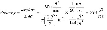
3.0” piping will have velocity at 203FPS. (.18 mach)
2.5” will be 293FPS. (.26 mach)
2.25” will be 361FPS (.32 mach)
2.0” will be 457FPS. (.40 mach)
Now assume EGT is around 1500* at WOT in boost. Mach is now 2169 FPS. So .4 mach is 867 FPS.
3.0” piping will have velocity at 390FPS. (.18 mach)
2.5” will be 585FPS. (.26 mach)
2.25” will be 694FPS (.32 mach)
2.0” will be 867FPS. (.40 mach)
So according to my rough *** math, which may be VERY wrong!
2” is right at the do not cross point for a motor that flows 600CFM aka 400 NA crank hp. So temperature seems to make no difference if your calculating velocity in piping for cold or hot side...
And if thats true does the amount of boost you plan on running really matter either when selecting piping size? A motor that flows 600cfm NA will flow 600CFM boosted as well. The air charge will just be more dense.
Assuming a 400 crank hp NA engine flows roughly 600CFM (1.5*400)
We use corkys velocity formula to figure air velocity in FPS through piping. (Assuming sea level and 68*F) AKA Cold size piping.
(This is the formula for 2.5")
3.0” piping will have velocity at 203FPS. (.18 mach)
2.5” will be 293FPS. (.26 mach)
2.25” will be 361FPS (.32 mach)
2.0” will be 457FPS. (.40 mach)
Now assume EGT is around 1500* at WOT in boost. Mach is now 2169 FPS. So .4 mach is 867 FPS.
3.0” piping will have velocity at 390FPS. (.18 mach)
2.5” will be 585FPS. (.26 mach)
2.25” will be 694FPS (.32 mach)
2.0” will be 867FPS. (.40 mach)
So according to my rough *** math, which may be VERY wrong!
2” is right at the do not cross point for a motor that flows 600CFM aka 400 NA crank hp. So temperature seems to make no difference if your calculating velocity in piping for cold or hot side...
And if thats true does the amount of boost you plan on running really matter either when selecting piping size? A motor that flows 600cfm NA will flow 600CFM boosted as well. The air charge will just be more dense.
Last edited by Forcefed86; 01-24-2014 at 12:50 PM.
01-24-2014 | 12:48 PM
#233
Thread Starter
7 Second Club
iTrader: (11)
Joined: Jul 2002
Posts: 8,758
Likes: 9
From: Port Tobacco, MD
I really don't have the desire to debate theories. Build your hot side with 2 different crossovers and report back with the data. Take it to the track and record boost response over the first 1.5 seconds. Let me know what you find out. For the record I am 455 cubic inch on methanol, I would build a set of 1 7/8" headers if time permitted to replace my 2" ones and stay on a 2.5" crossover.
01-24-2014 | 12:54 PM
#234
I really don't have the desire to debate theories. Build your hot side with 2 different crossovers and report back with the data. Take it to the track and record boost response over the first 1.5 seconds. Let me know what you find out. For the record I am 455 cubic inch on methanol, I would build a set of 1 7/8" headers if time permitted to replace my 2" ones and stay on a 2.5" crossover.
Your first post does say "Discuss..." So I Was just throwing it out there to try and understand myself. I was debating with some other folks on a different thread and they suggested I post in here so all could see.
Thanks for doing all the work by the way!

Last edited by Forcefed86; 01-24-2014 at 12:59 PM.
01-24-2014 | 01:23 PM
#235

Launching!

Joined: Feb 2011
Posts: 234
Likes: 1
Anytime you increase the pressure in a given pipe size you increase the velocity through it.
The greater velocity through a given pipe size the closer you come to your "magical" .40 mach limit.
01-24-2014 | 01:38 PM
#236
Thread Starter
7 Second Club
iTrader: (11)
Joined: Jul 2002
Posts: 8,758
Likes: 9
From: Port Tobacco, MD
I'm not calling anything you did incorrect or trying to debate with you specifically. If anything I'm sure I screwed up math at some point.
Your first post does say "Discuss..." So I Was just throwing it out there to try and understand myself. I was debating with some other folks on a different thread and they suggested I post in here so all could see.
Thanks for doing all the work by the way!
Your first post does say "Discuss..." So I Was just throwing it out there to try and understand myself. I was debating with some other folks on a different thread and they suggested I post in here so all could see.
Thanks for doing all the work by the way!
01-24-2014 | 01:51 PM
#237
" An increase in the speed of the fluid occurs simultaneously with a decrease in pressure or a decrease in the fluid's potential energy".
Just like a cylinder head flows 300cfm NA, it will flow 300cfm at 30lbs of boost as well. Wouldn't this also apply to an engine as a whole? A 3 liter engine will displace 3 liters. NA or at 30lbs of boost?
Last edited by Forcefed86; 01-24-2014 at 01:57 PM.
01-24-2014 | 01:58 PM
#238

CFM is always constant no matter what the density is with relation to temperature, but your mass flow rate will vary.
So factor your mass flow rate at WOT temps and desired altitude then work back to desired cross section to achieve desired CFM.
So factor your mass flow rate at WOT temps and desired altitude then work back to desired cross section to achieve desired CFM.
01-24-2014 | 02:32 PM
#239
Launching!
Joined: Feb 2011
Posts: 234
Likes: 1
Yep...What he said. ^^^^
Mass flow rate=velocity.
Think of it like this...
If you have a 150 grain 30 caliber bullet with x amount of powder (pressure) and increase the amount of powder (pressure) the bullet will be traveling at a higher velocity due to a higher mass flow rate of the gas.
Mass flow rate=velocity.
Think of it like this...
If you have a 150 grain 30 caliber bullet with x amount of powder (pressure) and increase the amount of powder (pressure) the bullet will be traveling at a higher velocity due to a higher mass flow rate of the gas.
01-24-2014 | 03:24 PM
#240
I like all this discussion, actually learning alot from this thread. I am in the middle of changing my setup because of this tread and will report back with data. Setup is a 8.5cr 370, 317 heads, TU1 cam, pro-flo intake, PT88, A2A intercooler, through a 3600stall and a 4L80E. 91octane pump and meth.
Changing from 1.75" 16g tube headers, 2.5" 16g crossover with a 3" 16g merge to F-body LS3 manifolds, 2" sch10(2.13" id) crossover with a 2.5" sch10(2.63" id) merge. Both with a 60mm JGS gate. The old cross over was about 5ft of tubing and the new one is about 3ft.
Hopefully be done in the next week or so. I have full data logs from the old setup to compare when done. The next time the motor is out, I will be bolting on a set of 243 heads to bump up the compression.