When you click on links to various merchants on this site and make a purchase, this can result in this site earning a commission. Affiliate programs and affiliations include, but are not limited to, the eBay Partner Network.
This BMR radiator cover would make a 'bling' addition to your car if you don't already have plans to install one. It looks as if BMR revised it so it has cut out slot to expel air as it passes up from the air dam to the radiator. My BMR version doesn't have the cutout slot .
I thought the slot was a dumb idea and blocked the slot in the ATI cover and saw a drop in coolant temps.
Interesting - I have both, so might swap next summer and see if there is a difference. I no longer have the condenser in front of the radiator, now, so might get different results.
But not sure how ATI tested or why they designed the cover with slots. But they were in denial for the longest time that 3 1/2 inch dual intercoolers and a single fan would keep IAT's and coolant temps down too, so who knows how they test.
You guys talking about the slot on top that would be between the ac condenser and radiator?
I was thinking of getting the BMR plate but not sure if the polished version would be too much bling. I did pick up a LT1 radiator cover for cheap, not sure if it will work though.
yes, slot on the top between the AC cond and radiator. I sealed it off with garage door gasket and it worked well. The whole point is to not leak air out and force it through the rad/cond. I contacted Bob @ Brutespeed about it and he was going to contact ATI, but never heard anything about why they chose to slot it.
I did the BMR on my 1st turbo build and it was nice, but when I went the blower route on my current car I didn't want all the bling so went with the ATI shroud as I couldn't find an LT1 shroud local. The LT1 shroud is good for a clean stock look.
The LT1 piece seems to fit on pretty good, might have to seal it up more with weather stripping or equivalent. Kinda goes with my theme I'm looking to do with the car.
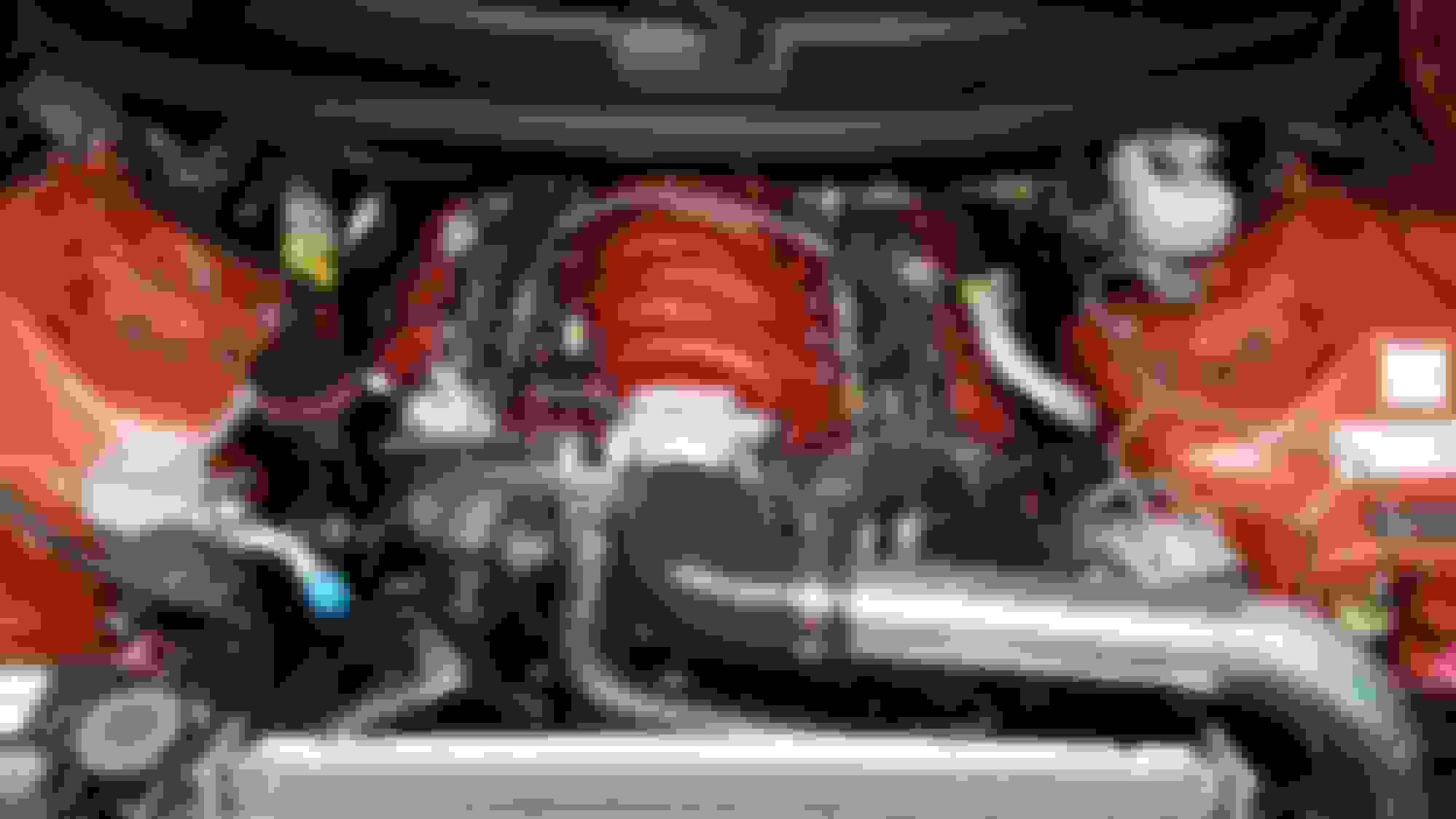
Now that the cold side is done, I'm able to see where I'll have clearance for the Alky meth pump and Vacuum manifold.
In the instructions that came with the meth kit, it's stated that the pump needs to be at the lowest point of the system, then the meth tank and last, the nozzles need to be the highest part.
I decided to mount the pump on the drivers side main frame rail, behind/below the headlight. Drilled 4 holes and done. From the top looking down, you don't really see it at all, kinda blends in well.
I bought this Vacuum Manifold from Ebay for about $17.00. It comes with everything you need to add your vacuum / boost accessories.
With my quest to hide as much as possible and have a clean OEM look, I mounted the manifold on the cruise control module bracket on the drivers side. It's away from the heat and out of sight. I swapped out the barbs to brass units that have a slightly larger ID.
The manifold tucks up nice, and I should be able to get the factory plastic shield back on with ease.
Throw some small zip ties around all of those boost referenreferel ask me how i know 😑🤦dum♂️
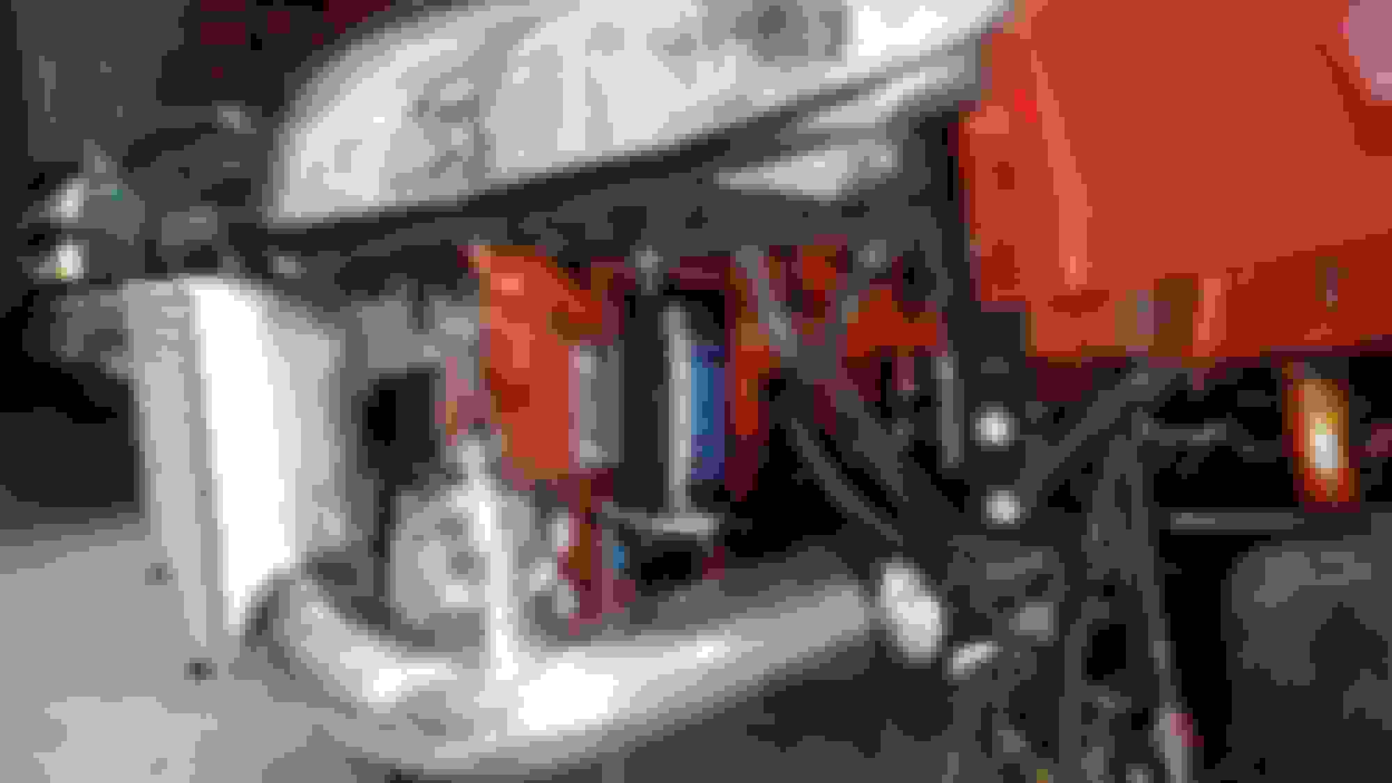
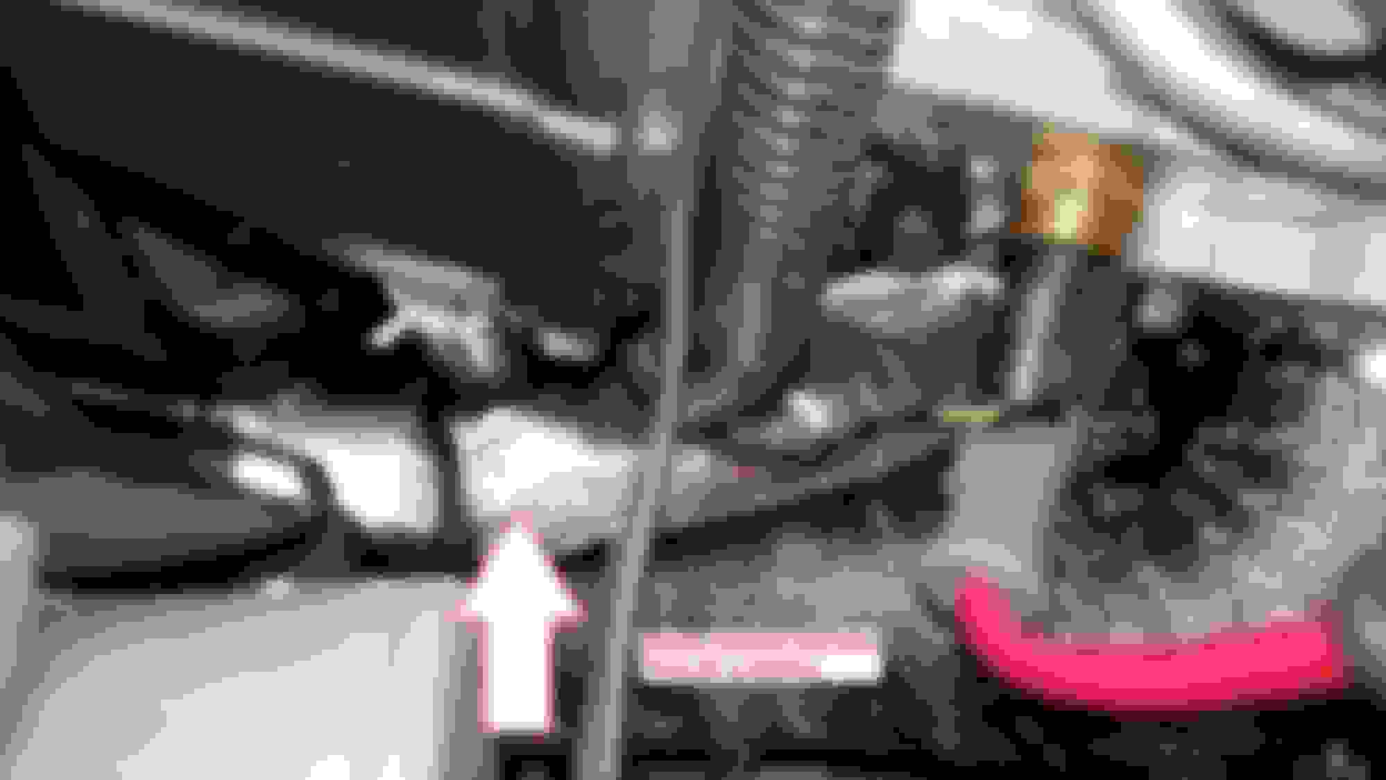
One of the areas that needs some extra attention is the wire that goes to the Alternator. In a NA car, as you know the headers go back toward the rear of the car and the alt wire clears everything. With the Huron Speed AC Turbo kits, you have almost no room to properly route the positive red wire that goes from the battery to the Alt since all the piping goes towards the front of the car and the turbo DP exits on the drivers side. Again, I tried to do some research on how to properly route the Alt wire from the battery to the alt around all the turbo piping. Very little good info is out there.
I asked Jon from Huron Speed on how to route the Alt wire and never got a clear response, he just said it will clear the piping and to make sure it doesn't touch... hmmm.... So after a few hours of trial and error, I found a way to route it so nothing will melt. I used heat sleeves and zip ties so I have at least 1/2" clearance from the turbo piping. It's kinda hard to see in the pics but I can get my fingers in between all the close spots.
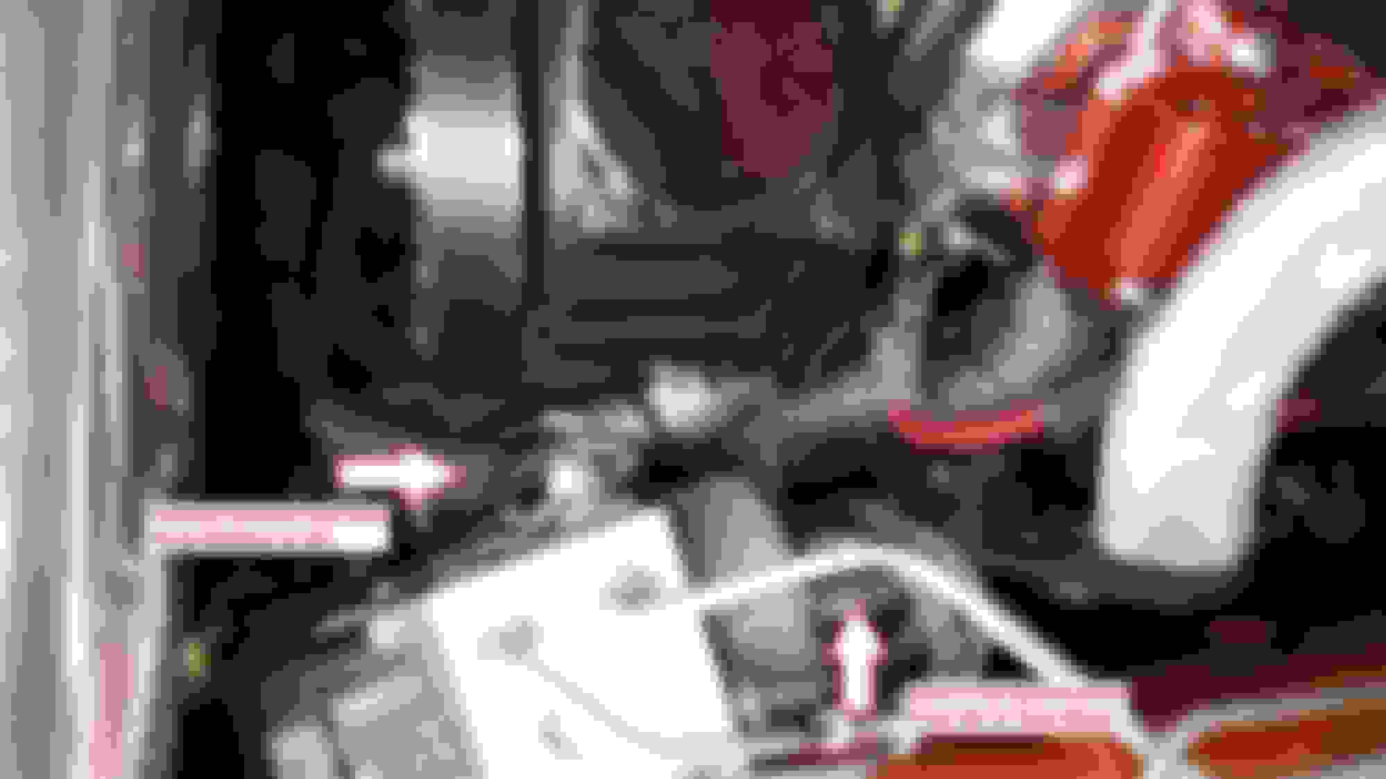
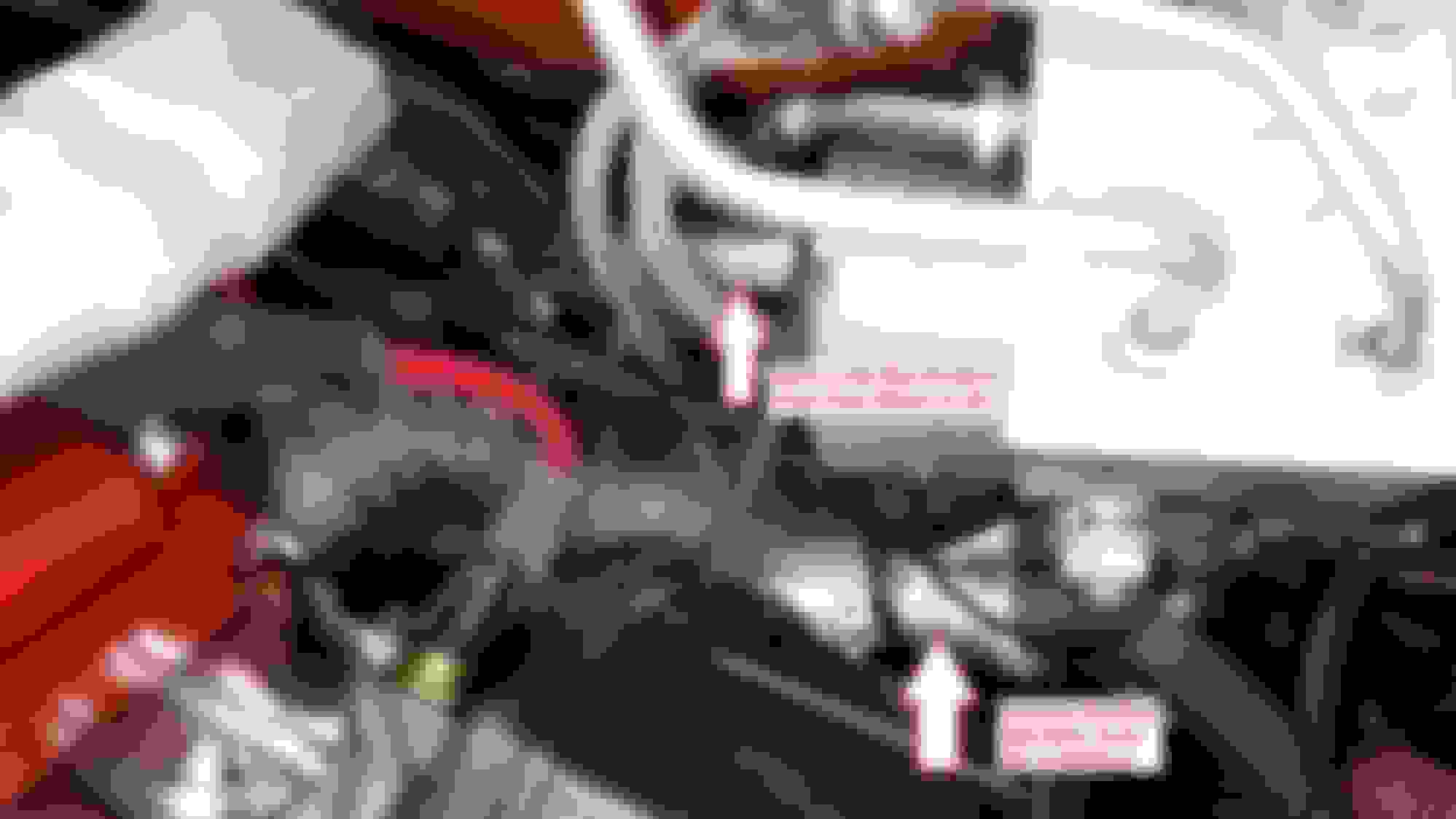
With the additional load that I will be placing on the cars electrical system, I added an extra 8 ga Red Positive wire from the Alt to the Fuse Block next to the ABS module. Since I upgraded my Alternator to a 185 AMP unit, the factory wire that goes to the battery is not big enough to handle the current. From the looks of it, it seems to only be 4 ga wire. If a wire is hot to the touch, the wire is way to small. Routing that wire was a challenge as well. In the pics below, hopefully you can see how it was done.
With everything so tight, it was hard to get good pics of both wire routing. I routed the 8 ga wire under the ABS module for 2 reasons, 1st, because it was a perfect path for the wire and kinda held it in place away from the manifold, 2nd, it also hid the wire some for a cleaner look.
With the 12 volt positive side upgraded you can't forget about the negative side of the system. On the passenger side of the engine block, I added a 4 ga wire from the block to chassis ground. (Main Frame Rail)
Both wires I added are 100% pure copper with a high strand count to make them super flexible. I crimped and soldered the ring terminals as well for the best electrical conductivity.
If the factory wire was about 6 inches longer, I would have went a different route for a cleaner look. I used zip ties to hold the wires in place but not too tight since the engine moves around some and didn't want tension on the wires.
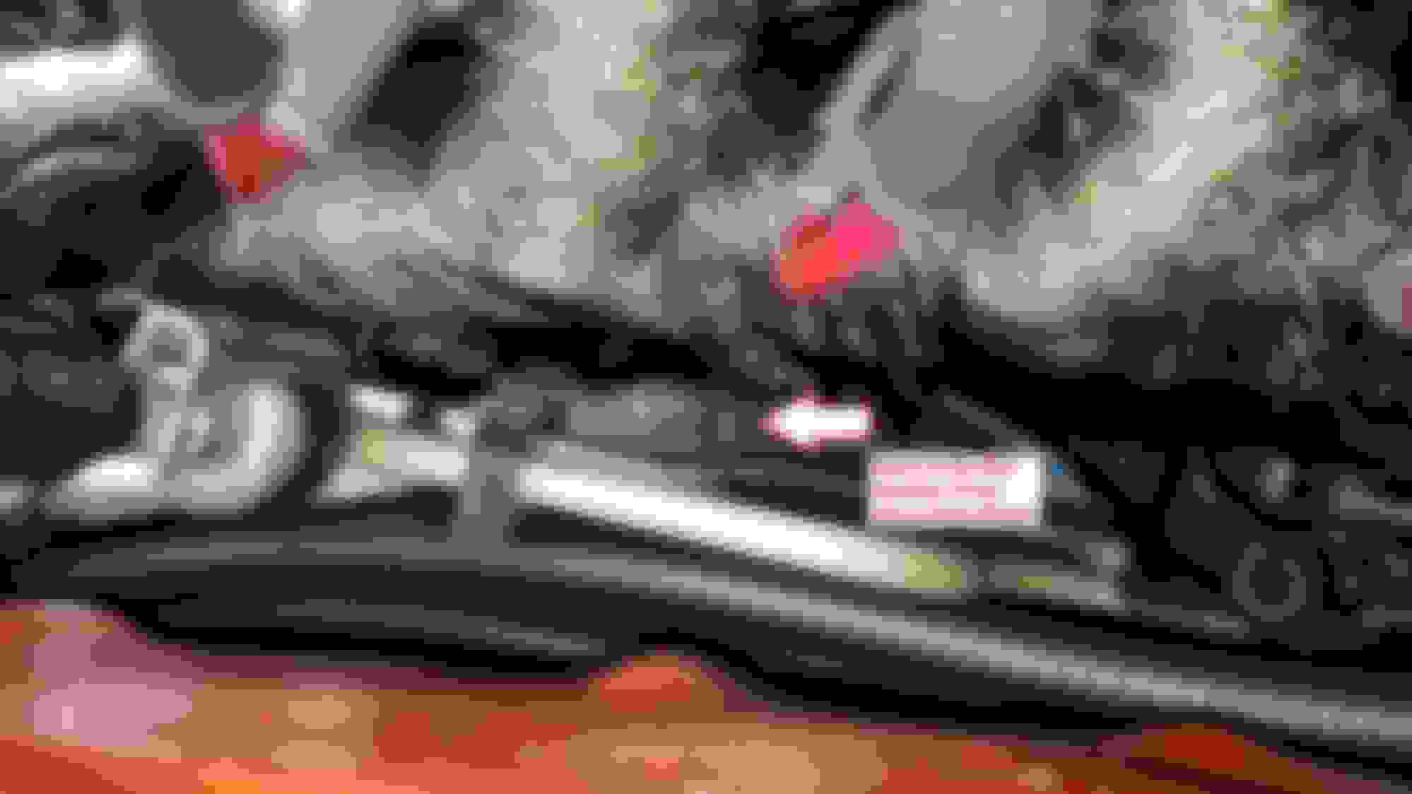
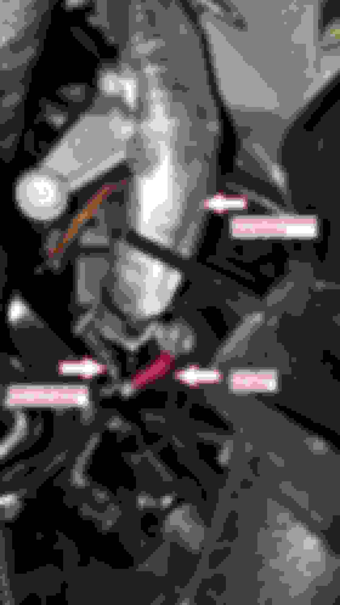
The extra 8 ga red positive wire has wire loom with a heat sleeve over top of that for protection. I loosely put a zip tie to the fuel line to help hold it so it doesn't drop down at all.
You can't really tell but there is about 1/2" clearance from the wire to manifold.
I loosely put a zip tie around the factory wire to the K - Member engine mount support to help keep it in place.
I added a star washer under the bolt head. The tines dig in so you have a better electrical connection.
The 4 ga ground wire is about 14-16" long and has a slight loop for flex to absorb the engine movements.
I attached the other end to the sway bar bracket bolt going to the main frame rail. This view is looking up at the bottom of the main frame rail. I also used a star washer under this bolt as well for a better electrical connection to ground.
With the LS3 top end on a LS2 short block, you have to come up with a solution for your LS1 throttle body cable to work on a LS3 Intake since the LS3 only came with DBW. I found a great throttle cable bracket that works great from Metaltek. It has a OEM look and fits great.
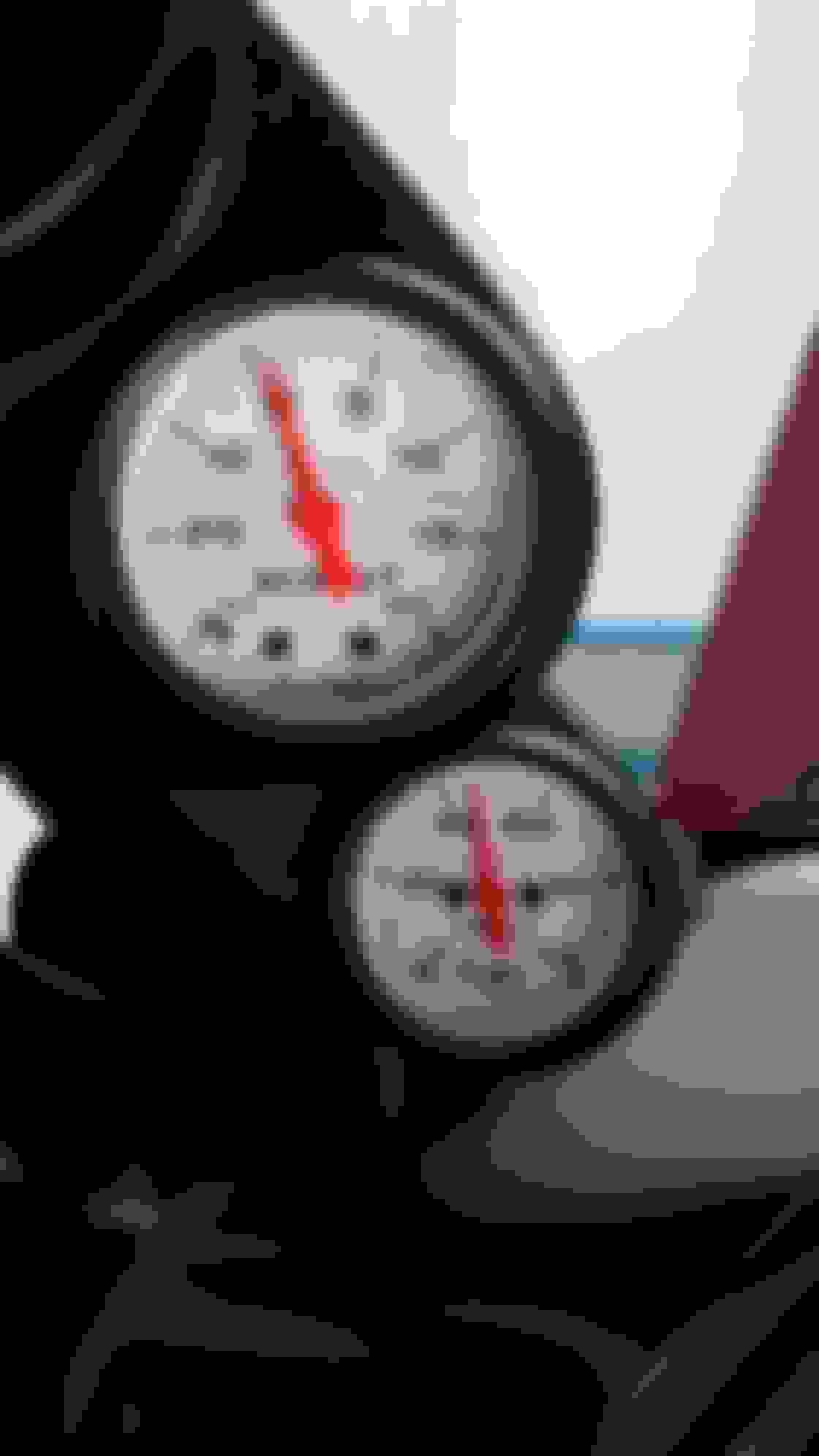
It's time to install the boost controller solenoid and gauges.
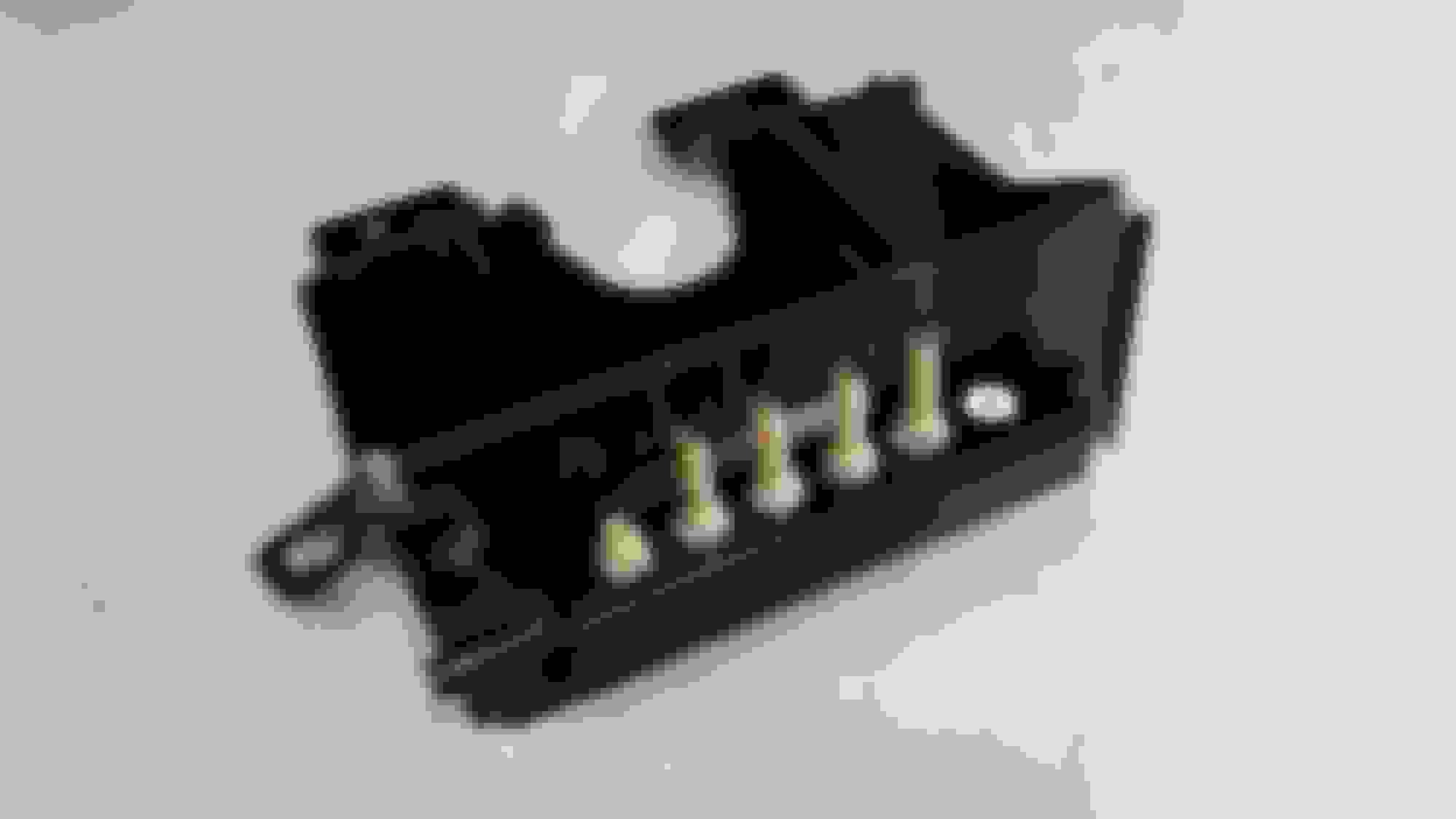
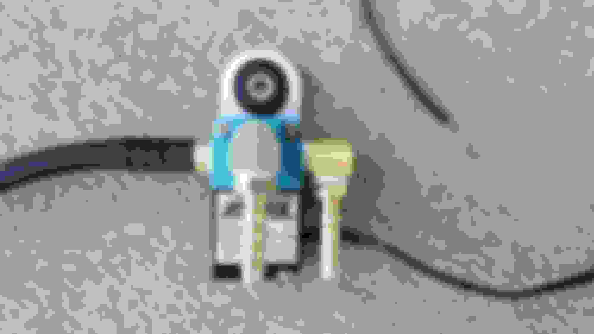
When it came to finding a place to mount the boost controller solenoid, I knew I wanted to mount it away from any heat sources. There is a factory hole behind the drivers headlight which ended up being the perfect spot for it.
The boost solenoid is tucked away nicely.
Here's my makeshift vacuum manifold I built for inside the car.
Since the car never came with traction control, there is no adjustment for the throttle cable. Ever since I installed the LS3 into my car years ago, I had a little slack in the cable. The gas pedal has a little cup for the end of the cable to sit in, but with the slack, it was never in it so I came up with this. These are brake parts from my sons old bike. Not sure whats it's really called but it made out of aluminum, it has a slot in it to go over the cable and the nut and zip tie holds it in place. Now it fits in the cup and the slack is gone.
Wires that need attention...
The goal is to max out the boost gauge. I'll have to upgrade my fuel pump and lines before that's possible.
To be able to drive the car, one last thing I had to do was to extend the last pipe of the hot side so it sorta exits the engine bay. I bought a 3 foot, 3" flexible exhaust pipe from Summit Racing for about $16.00. I just used a basic 3" clamp up by the engine and used stainless wire to hold the other end up. After looking at it, I decided to add plumbers metal strap for extra support. It looks kinda cheesy, but it will get the job done so I can at least drive the car around some and get it to a custom exhaust shop later on.
When I get it up on a lift, I'll be getting better pics of the underside.
The car is finally ready to take a test drive!!! Coolant is in and I temporarily hooked up the fans. It's pretty much done except for the fan harness, catch can, bumper cover and a few other odds and ends. I loaded a 3 bar OS into the PCM and did some basic idle tuning while sitting in the garage so it can run.
It's officially out of the garage under it's own power!
I went up and down my road a few times with no issues. With it being an open header off the turbo, it was no louder than what I had before. It will be a sleeper for sure once it's going through the catback. Everything looked good on the scan so I went around the block in my neighborhood once and all is good. I got a few odd looks from my neighbors since it didn't have the bumper cover on, a few others gave me a thumbs up and said it sounds great.
Surprisingly, the car goes straight but the steering wheel is off a bit. A few times I leaned into it just enough to see the boost gauge go slightly into boost, hear the turbo spool and heard the blow off valve work. I was all smiles...
Now that the car can move under it's own power, I need to finish the install of the catch can. About a year ago, I contacted Mighty Mouse to see what catch cans he had available for my application. He suggested I go with his 'Wild" set up. This should be able to handle 1000 HP. Install is pretty straight forward as you can see in the pics. The one thing you can't see is the little breather filter on the rear of the drivers side valve cover.
 11-19-2018, 10:27 AM