When you click on links to various merchants on this site and make a purchase, this can result in this site earning a commission. Affiliate programs and affiliations include, but are not limited to, the eBay Partner Network.
Trap door/Racetronix pump/Hotwire kit INSTALL **lots of pics**
This was done on my 2002 Z28. My car began having trouble starting sometimes. It would require two tries to finally start unless I turned the key to let the pump work for a minute before trying. I decided to swap the pump with a Racetronix pump and also run the Hotwire kit at the same time. I broke my project down over a few days due to work and not wanting to rush and make a mistake. I even had to add a day because Racetronix doesn’t include instructions for their wiring harness and had to re-do a portion, which was frustrating. Did I say frustrating? I meant infuriating. Without further ado:
DAY 1: TRAP DOOR
Special tools: Dremel w/ cut off wheels and grinding stone
Pop rivet gun w/ 1/8” aluminum rivets
First you should DISCONNECT THE BATTERY, then remove the rear sail panels in the hatch to allow you to peel the portion of carpet covering the deck toward the front of the vehicle. It’s not attached to the body or anything so it’s pretty easy.
Now go under the car and drop the tank a little to help avoid cutting wires when creating the door. It’s a very easy process that involves jacking the car up on the passenger side and loosening five bolts. The first being the three 15mm bolts holding your upper panhard bar, and then the two 13mm bolts holding the gas tank straps. This should drop the tank about an inch, which is all you need. The bolts are shown below, respectively.
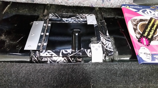
I decided to cut my door a little bigger to aid with the fishing of the wiring harness and to give me a little more room to work with during the pump removal/install. I’m glad I did. I just traced out a square as shown with my measurements EVENTUALLY being 9.5”x 9”. I originally cut bigger but discovered there was a support brace that got in the way and so it was repaired with some aluminum sheet metal and 1/8” aluminum rivets. BTW, I had never used a pop rivet gun before and couldn’t believe how easy and cheap it was. Just go slow with the cutting wheel, making several passes over the line you traced until you go through the metal. Use caution in the highlighted sections as they represent the areas where it’s possible to go too deep and cause damage. Total time to cut the hatch was about 20 minutes. Make sure you clean the area up at this point to minimize the risk of getting dirt into your tank.
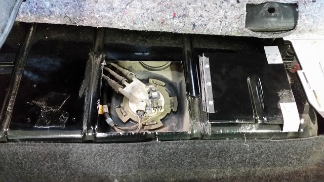
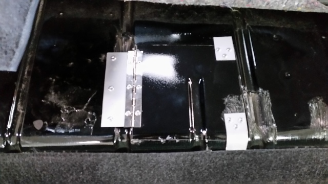
The cuts on the hatch and door (I used the original cut piece) were cleaned up with the grinding stone on the Dremel and the hinge was installed on the door. Mark, drill hole, rivet, repeat. I cut two squares from some steel sheet metal to install as stops. I chose these corners as I will screw them down when finished with the project and there aren’t any wires/hoses in the area to accidentally damage. The door was then installed on the hatch with additional rivets.
I then used some spare sound deadener to clean it up and also give it some support. This was a great addition, especially on the door.
DAY 2: PUMP SWAP
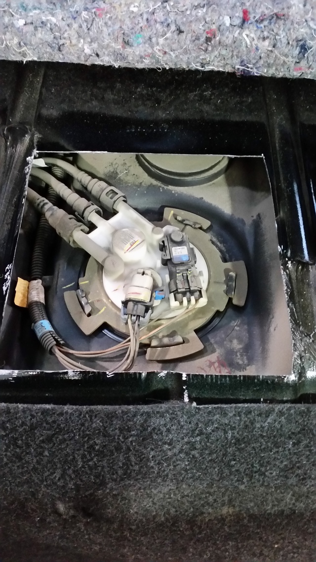
First you need to disconnect the wires and hoses. I used different colors of my wife’s nail polish to mark the proper hose to its connection, which is overkill, but that’s just how I am. Next comes the infamous locking ring. The best method by far is to use a big flathead screwdriver and big hammer. Then just work your way around the ring, giving each notch a couple whacks. Eventually, it will unlock and you can carefully slip it out and around the top of the fuel pump assembly. Next, you’ll want to grab a bucket and a bunch of paper towels for removing the assembly from the tank. Just be careful, the assembly bucket is full of fuel and the gas level float sticks out some. Once you’ve dumped the gas into the bucket, you’re ready to start disassembling the assembly to install your Racetronix fuel pump.
Now follow the instructions Racetronix gives you for swapping the pump out with a caveat: instead of the safety pin they provide to remove the wire clip ends, I used a sewing needle which works WAY better. The needle goes in the notch portion as shown in the photos.
**IF YOU ARE GOING TO INSTALL THE HOTWIRE KIT, FOLLOW THESE ADDITIONAL INSTRUCTIONS: ***
Find the special wire harness that will attach the pump to the top of the assembly in the hotwire kit. It is different than the one that comes on the Racetronix fuel pump so remove that one and install the harness from the hotwire kit onto the pump before doing anything. Next you’ll want to insert the two purple fuel level sensor wires into the new plug, it doesn’t matter which slot you put them in so it’s idiot proof. Next you’ll want to replace the top plug with the one provided in the Racetronix hotwire kit. Then you can put the whole assembly together using the instructions included with the fuel pump.
***END OF ADDITIONAL INSTRUCTIONS***
Now, I have been having problems with my fuel gauge, especially after getting fuel. It would read full, and then drop to “empty”, and go back and forth several times before reading correctly. After doing some research, I purchased a SUR&R GM64 fuel level sensor and followed the instructions on their Youtube video (except I used rubbing alcohol on a Q-tip instead of spraying it with carb cleaner). It was really easy and the dial used by the sensor was very dirty. I also had a few sensor contacts on my stock piece missing, which explains a lot. Below is a pic of it installed and it has subsequently solved all of my fuel level problems. Highly recommend.
Alright, now time to re-install the assembly. I used some of the grease supplied in the kit and smeared it on the rubber seal that sits under the lip of the pump assembly. I also used a turkey baster to put some fuel back in the assembly bucket around the pump in order to “prime” it. Re-install the locking ring using the same technique as earlier. Now on to the hotwire harness…
Now just re-install the locking ring using the same method and re-connect the fuel hoses.
Last edited by NineZeroFive; 08-07-2015 at 03:01 PM.
First you�ll need a hangar, bend it straight with a small curl at the end. Insert it from the trap door to your ten o�clock, following the stock wiring. Then look underneath and make sure you can see it peeking out from above the gas tank. Now, take your harness with the two plug end and wrap it in masking tape as shown below. Take one of the small zip-ties included in the kit and run it through the connector as shown to give you something to hook the hanger onto. This reduces the profile of the plugs and prevents it from snagging as you pull it through. Easy.
Now attach the Racetronix wiring assembly to the top of the fuel pump assembly and old stock wiring harness as shown in the pictures. Time to go back under the car.
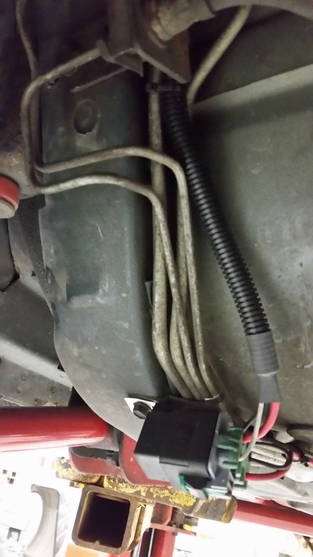
You�ll need to drill a hole and use the self-tapping screw provided to secure the black relay box, then run the wiring harness towards the front of the vehicle. I used the same route as my fuel lines along the driver�s side to get it to the engine bay. I used the black zip ties provided every 12� or so. This was not difficult at all.
Once you get it to the engine bay, you�ll have the option of mounting the fuse somewhere. I really wish there was more wire to mount it near the rest of the fuses but there isn�t. I tucked it away near the location of the A.I.R. pump for now but plan on soldering an additional length of wire at a later date to mount it properly near the other fuses and hood.
Now connect the ring terminal at the end of the wiring harness to the alternator post. You will need to loosen/remove the bracket bolts to reach the alternator post which is hiding under a protective rubber boot. Tighten all the bolts and reconnect the battery. Turn the ignition to ON and listen to hear the pump kick on. Start the car and let it idle for a bit before you go on a test drive.
Didn't take pics of this last part because it was pretty self-explanatory and I was running low on daylight. I hope this helps someone else!
Last edited by NineZeroFive; 07-29-2015 at 05:55 PM.
1. The safety pin is fine for releasing the terminals. It is only meant to depress the small tang on the terminal down so it can release from the connector cavity. If the pin is bending then too much force is being used. The pin is not meant to push the terminal out. Gently pulling the terminal from the back side of the connector while the tang is depressed should be enough.
2. We do not condone the use of the trap door method. Tanks of this age must be removed and properly cleaned. Racetronix will not honor warranty on pumps which have been damaged due to contamination.
. There have been some cases of fire / damage to the wiring and lines due to the cutting process. Insurance companies may deny coverage if the vehicle is modified in this fashion.
3. The relay should be mounted on the same bracket as the ground ring terminal as shown in the attached picture. There is no need to drill holes to mount the relay. The metal surfaces should be cleaned to bare metal in the contact area with sandpaper or a wire (wheel) brush. All surfaces should be coated with a thin layer of silicone grease supplied in the kit. This includes the ground terminal and the relay bracket. This will prevent corrosion and ensure a good ground. The relay should be pointed with the wires facing down so water does not pool in the seals. There should be at least 1-2� of slack in the wires coming out of the relay so that the seals are relaxed / not stressed. This will prevent water from entering the connections.
4. The plastic factory venturi tubes are dry and brittle. They should not be reused. If this tube leaks or comes off it will cause fuel starvation, low pressure and pump damage. Racetronix now includes a superior conductive Teflon tube with all FPA-001B assemblies.
Racetronix,
Thanks for the reply. I'll make those changes in a few weeks.
If you guys could add a few feet of wire between the fuse and end ring terminal to the alternator to allow better mounting of the fuse, that would be awesome.
That, and instructions in the Hotwire kit, haha.
I cut my trap door yesterday, just got it in the shop to finish it tonight. I really like this mod!
Got my racetronix pump & hotwire kit installed also. Their instructions on the venturi hose was very poor. My pump already had the venturi line attached. I had to remove it from the pump so I could install it on the fitting in the bucket 1st. You'll need a long knife to cut the old one. It was impossible to fit the relay in the brake line bracket bolt, them 2 lines are right in the way. I wanted to mount it with the wires straight down but didn't feel like making more holes in the body so this is where I mounted it.
Looks pretty good! The position of the relay makes me nervous about it possibly getting hit by road debris though. I figured I already cut a hatch in the body, so what's one more hole for the relay mount? Haha.
Last edited by NineZeroFive; 08-06-2015 at 02:47 AM.
Looks pretty good! The position of the relay makes me nervous about it possibly getting hit by road debris though. I figured I already cut a hatch in the body, so what's one more hole for the relay mount? Haha.
You know that's right! Had the car on the trailer & looking at how the relay hangs down makes me a lil nervous. Gonna mount it higher
Looks pretty good! The position of the relay makes me nervous about it possibly getting hit by road debris though. I figured I already cut a hatch in the body, so what's one more hole for the relay mount? Haha.
The bracket is the best place to ensure a solid mount, grounding location and water drainage. There would be much more to worry about such as break lines in this area if it was a susceptible to damage which it is not.
The bracket is the best place to ensure a solid mount, grounding location and water drainage. There would be much more to worry about such as break lines in this area if it was a susceptible to damage which it is not.
As you can see from our 2 pics of where the relay is supposed to mount, mine has an extra brake line back there so the relay will not fit behind them. 00 SS 4 channel system, maybe that's the difference. I did drill & self tap the relay just below the lines. It was in a bad spot where I had it mounted.
Just wanted to thank you for this write up. The Racetronix instructions were awesome, if you were only doing the fuel pump. With the Hotwire kit, they don't add instructions, so your write up saved me some headache! Thanks!
Just wanted to thank you for this write up. The Racetronix instructions were awesome, if you were only doing the fuel pump. With the Hotwire kit, they don't add instructions, so your write up saved me some headache! Thanks!
I received my hotwire kit and pump today and im pretty ticked off about the so called support i got. The fact that racetronix wants to correct every install but then doesnt include instructions is infuriating. I called texas speed and the tech line ahole told me to google it. I will never order anything from either of those companies again unless they rectify this bs.
The fix is simple...... include instructions for your product in the package. I simply dont understand why its so hard. I have found numerous others complaining about this. I already regret buying this product.
My local speed shop ordered the hotwire kit and pump from Racetronix for my 95 LT1. Both came with very detailed and color instructions.
It's complete with OEM connectors/safety clips, grease, and even a OEM style female ground clip for the pump.
I was impressed with the packaging and level of detail in this kit. Just got the install done last night and all went well. I plan to get a test drive in this weekend.
BamaWS6...maybe the vendor you used cobbled together the parts to send to you? My pump kit had very blatant tape/sticker saying that if it the seal was broken, NOT to use the kit. Basically if it shows up "opened" then to contact Racetronix.
 07-29-2015, 05:46 PM