When you click on links to various merchants on this site and make a purchase, this can result in this site earning a commission. Affiliate programs and affiliations include, but are not limited to, the eBay Partner Network.
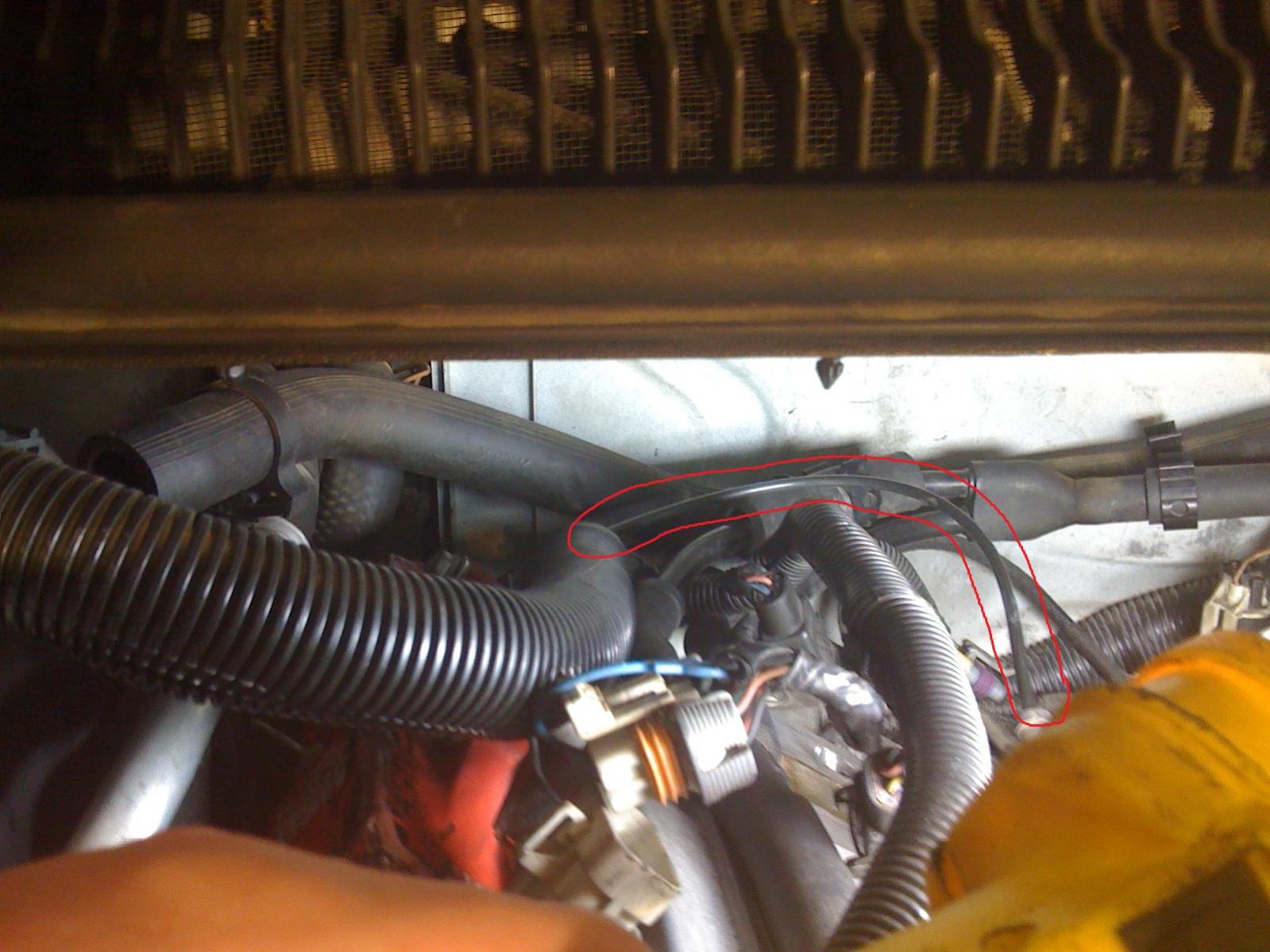
I have a vacuum line that comes out of the wiring harness on the passenger side... I've looked everywhere but can't find a diagram to figure out what it's for or where it really goes.
Right now it splits into a T one side is just open and the other side was connected to the back of the IM (under the sensor) but I'm thinking that is wrong. Perhaps the open side connect to the back of the IM and the other side connects to the sensor that connects to the AIR tubes?
pictures may be a little big / crappy but that's a camera phone for ya.
anyway... first picture is the vacuum hose i'm talking about.
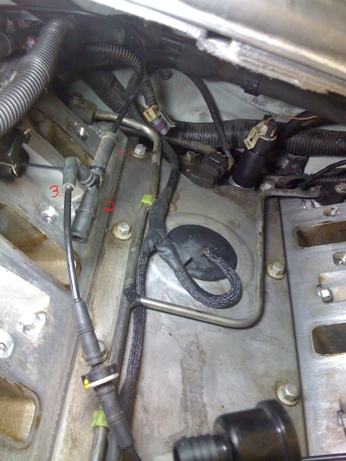
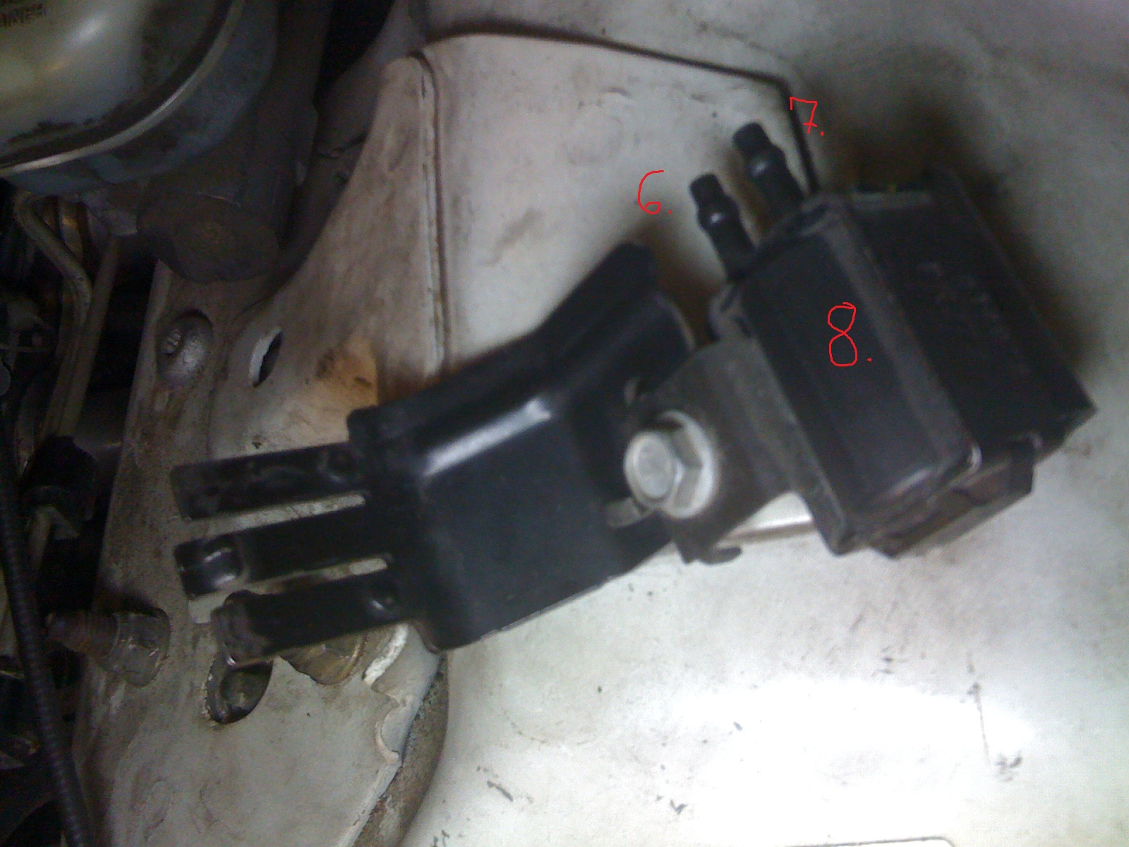
1 is the same hose but where it connects to the T
2 is the open end i was talking about (possibly should connect to back of intake #4? )
3 is what WAS connected to the back of intake #4
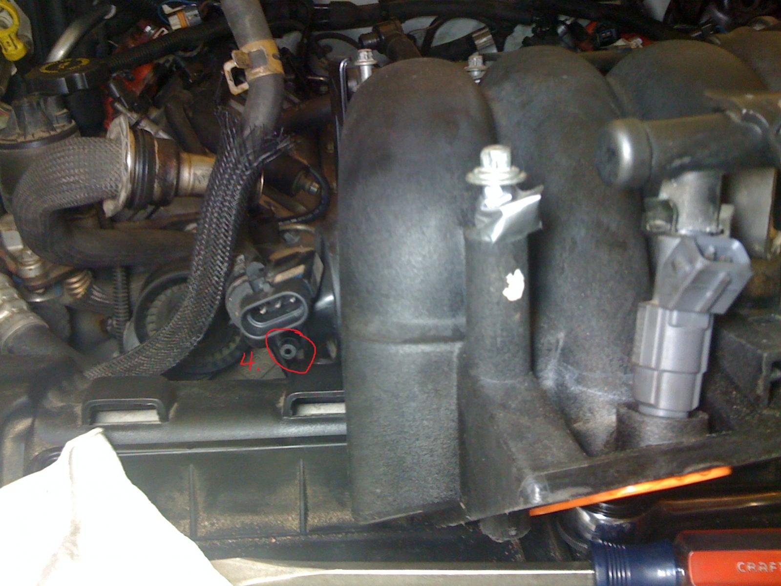
4 is obviously back of intake
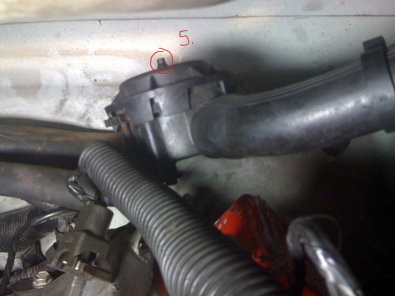
5 is top of air tube that was connect to #7 on the sensor #8
6 was left open
7 connected to air tubes
8 sensor
I'm in the process of pulling AIR on my '02, but I have a question with these lines. It seems every thread I read about removing AIR simply states to put a cap on "4" (referencing post 3 above) because 5-8 are removed. However, "1" goes somewhere (haven't traced where), so wouldn't we want to be capping "3"? If this is the case, why does everyone just leave "1" hanging out?
I hope this makes sense because it's driving me crazy.
Edit: "1" goes to the HVAC mixing door. Not sure why most AIR removal directions don't mention the need to keep those lines intact, but if you want to use your HVAC system, you simply remove "3" and put a cap on it (and all the other ancillary vacuum lines for AIR) while retaining "1" & "2". I hope this helps others that might run into this down the road!
Last edited by demonspeed; Oct 1, 2013 at 08:31 AM.
Would anybody happen to know the size of the hose in the first picture? I've been searching my butt off. I want to replace the whole line running from the vacuum cannister up the passenger side wiring harness to where it connects
I'm in the process of pulling AIR on my '02, but I have a question with these lines. It seems every thread I read about removing AIR simply states to put a cap on "4" (referencing post 3 above) because 5-8 are removed. However, "1" goes somewhere (haven't traced where), so wouldn't we want to be capping "3"? If this is the case, why does everyone just leave "1" hanging out?
I hope this makes sense because it's driving me crazy.
Edit: "1" goes to the HVAC mixing door. Not sure why most AIR removal directions don't mention the need to keep those lines intact, but if you want to use your HVAC system, you simply remove "3" and put a cap on it (and all the other ancillary vacuum lines for AIR) while retaining "1" & "2". I hope this helps others that might run into this down the road!
4 is your main vacuum source on the back of the intake manifold. You cannot cap this or you will lose your HVAC system entirely.
Since this ancient thread is already resurrected, I guess I'll fill in the blanks. My pictures aren't ideal, but they're pretty good.
The back of the intake manifold has two vacuum ports. One big one (3/8") for the brake booster, and one little one (1/8") for everything else. (This is an LS3 intake manifold; LS1 is similar.)
"Everything else" is the AIR system and the HVAC blend doors. IIRC, one of the two connections visible here goes to the manifold, and the other goes to the AIR canister. All you need to do is cap the AIR one. Personally, I removed the tee entirely, replacing it with a straight-through connector. Weight reduction!
The line that runs off the right side of the photo above tucks into the engine harness near the back of the passenger side head:
That line comes out of the harness again near the PCM.
There's a check valve (light-yellowish thing circled in the photo) going into another tee. One tee branch goes to the blend doors, and the other goes back into the harness along the left side of the photo above and heads forward, to the vacuum accumulator canister located under the frame rail to the right of the radiator:
6 Common C5 Corvette Failures and What's Involved In Repairing Them
Slideshow: From wobbling harmonic balancers to failed EBCMs, these are the issues that define long-term C5 ownership and what repairs typically involve.
Retro Modern Bandit Pontiac Trans AM Comes With Burt Reynolds' Autograph
Slideshow: A modern Camaro transformed into a retro icon, this limited-run "Bandit" build blends nostalgia with brute force in a way few revivals manage.
Top 10 Greatest Cadillac V Series Performance Models Ever, Ranked
Slideshow: Cadillac didn't just crash the high-performance luxury vehicle party, it showed up loud, supercharged, and occasionally a little unhinged...
Coachbuilt N2A Anteros Is an LS2-Powered C6 Corvette In Italian Clothes
Slideshow: A one-off sports car that looks like a vintage Italian exotic-but hides a C6 Corvette underneath-just sold for the price of a new mid-engine Corvette.


 My pictures aren't ideal, but they're pretty good.