
View Poll Results: YES OR NO?
INTERESTED


16
40.00%
NOT INTERESTED


24
60.00%
Voters: 40. You may not vote on this poll
NEW LID CAD Printout, Finally! *pics*
 02-19-2007, 04:24 PM
#1
TECH Apprentice
Thread Starter
iTrader: (2)

Join Date: Aug 2006
Posts: 384
Likes: 0
Received 0 Likes
on
0 Posts

This is just a thrown together copy! there will obviously have to be some adjustments and different versions! This threead is to see if you guys would be interested. I assume i would have to become a sponser to sell this product also.
Okay so im ganna have to explain this, most of you guys will get the idea but just incase.....Rite now our lids are just a square, so the air going in that isnt lighned up with the exit whole(MAF)/Neck of the lid is either getting stopped or bouncing back or some how making its way to the MAF. This lid has two sections that dropp down all the way to the bottum of the box that the lids sit on. and then would seal with the two corners, so that way, all the air coming is can onnly go one directoin, and thats towards the MAF/exit. Now in real actuality this part that is dropped down will have to come down a little lower and if this item gets prototyped well obviously have the correct measurments and what not. Then since that theres two sections that are lowered,we wouldnt be able to use the K&N or any sort of that style filter, so waht we would produce is a circular filter that would slide into the neck of the air lid. Sort of how in your MAF the screen is there, but only it would be in the neck of the lid.Or we could make one how they are now but just a fitted one. We wouldnt mind making a 90m either if this product seems worth your time. Heres some CAD prinouts, see if you can kinda get the idea.
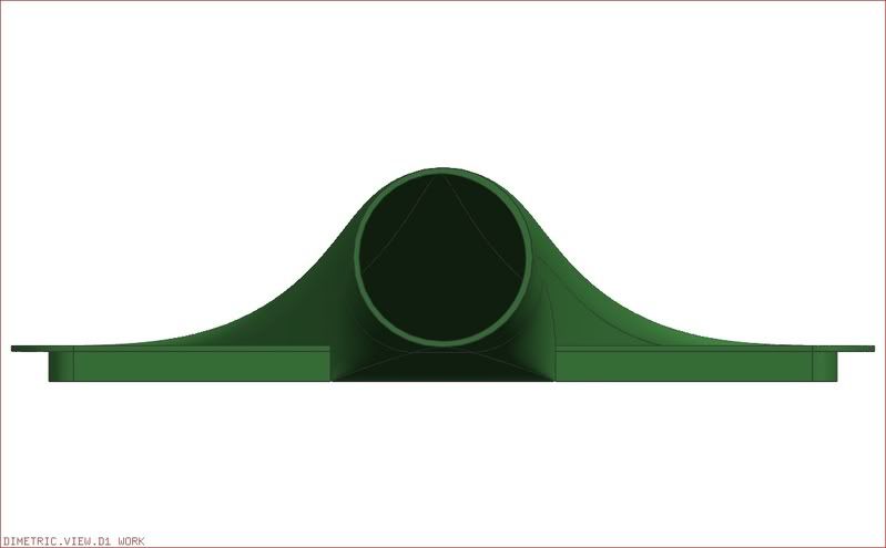

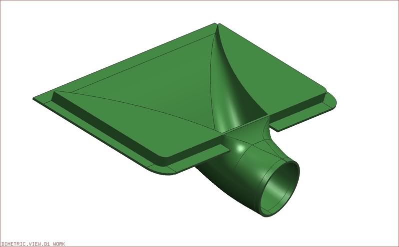
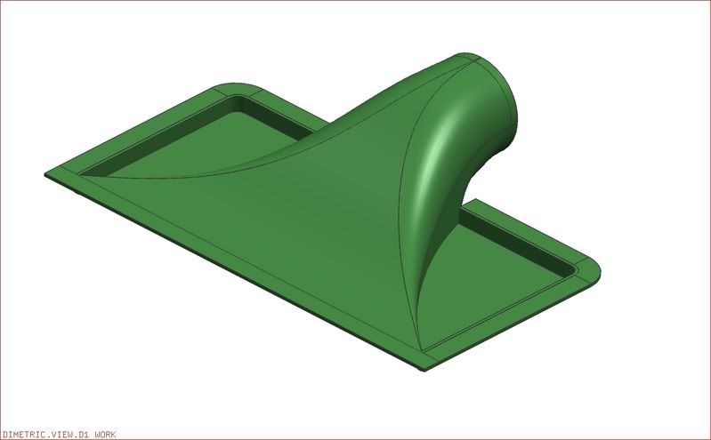
Okay so im ganna have to explain this, most of you guys will get the idea but just incase.....Rite now our lids are just a square, so the air going in that isnt lighned up with the exit whole(MAF)/Neck of the lid is either getting stopped or bouncing back or some how making its way to the MAF. This lid has two sections that dropp down all the way to the bottum of the box that the lids sit on. and then would seal with the two corners, so that way, all the air coming is can onnly go one directoin, and thats towards the MAF/exit. Now in real actuality this part that is dropped down will have to come down a little lower and if this item gets prototyped well obviously have the correct measurments and what not. Then since that theres two sections that are lowered,we wouldnt be able to use the K&N or any sort of that style filter, so waht we would produce is a circular filter that would slide into the neck of the air lid. Sort of how in your MAF the screen is there, but only it would be in the neck of the lid.Or we could make one how they are now but just a fitted one. We wouldnt mind making a 90m either if this product seems worth your time. Heres some CAD prinouts, see if you can kinda get the idea.
Last edited by sickws698; 02-19-2007 at 05:34 PM.

 02-19-2007, 04:37 PM
#7
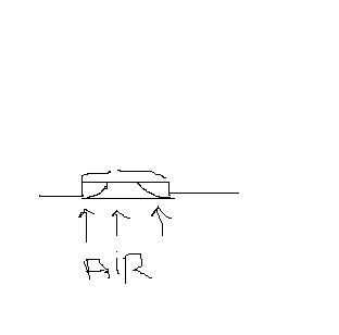
Where's the air filter going to go?
The stock lid keeps a volume of air in between the air and the filter from which the engine pulls. The air flowing into the filter isn't going at such a rate that it's affected by the air "bouncing off the back", it's simply flowing in to fill whatever may be sucked in through the throttle body.
The graphics work and stuff looks nice, but it's just hard to improve upon the lids functionality. Selling an "85mm lid" like TSP used to could make you a KILLING in these parts, much more than anything like this would. All you'd need is a rip-off of another design with a bigger hole.
Last edited by TheBlurLS1; 02-19-2007 at 04:43 PM.
Trending Topics
02-19-2007, 04:42 PM
#9
TECH Regular
iTrader: (14)

Join Date: Apr 2005
Location: Denver, NC
Posts: 434
Likes: 0
Received 0 Likes
on
0 Posts
just make a 90mm lid....the demand for it is already there. You would not have to convince people that the idea is gonna work like you are doing with this....just my 2cents
02-19-2007, 04:46 PM
#10
TECH Regular
iTrader: (1)

Join Date: May 2005
Location: St. Peters, MO
Posts: 489
Likes: 0
Received 0 Likes
on
0 Posts
Originally Posted by TheBlurLS1
Where's the air filter going to go?
The stock lid keeps a volume of air in between the air and the filter from which the engine pulls. The air flowing into the filter isn't going at such a rate that it's affected by the air "bouncing off the back", it's simply flowing in to fill whatever may be sucked in through the throttle body.
The graphics work and stuff looks nice, but it's just hard to improve upon the lids functionality. Selling an "85mm lid" like TSP used to could make you a KILLING in these parts, much more than anything like this would. All you'd need is a rip-off of another design with a bigger hole.
The stock lid keeps a volume of air in between the air and the filter from which the engine pulls. The air flowing into the filter isn't going at such a rate that it's affected by the air "bouncing off the back", it's simply flowing in to fill whatever may be sucked in through the throttle body.
The graphics work and stuff looks nice, but it's just hard to improve upon the lids functionality. Selling an "85mm lid" like TSP used to could make you a KILLING in these parts, much more than anything like this would. All you'd need is a rip-off of another design with a bigger hole.
02-19-2007, 04:52 PM
#11
TECH Junkie
iTrader: (7)
Join Date: Aug 2004
Location: Prairie de Femme, LA
Posts: 3,809
Likes: 0
Received 0 Likes
on
0 Posts
way too small of filter surface area. thats the reason that ppl use cone filters over just a flat filter on the tube. and  what the others said, 90mm would sell like crazy. good market with no offerings right now
what the others said, 90mm would sell like crazy. good market with no offerings right now
02-19-2007, 04:55 PM
#12
Well I already got my lid so I wouldnt be a potential buyer however I do wanna say this to you.
its a great idea, it seems logical and simple but I don't think it will be muchb etter than a normal lid. I think you did a good job and thinknig outside the box and i give you props for that.
its a great idea, it seems logical and simple but I don't think it will be muchb etter than a normal lid. I think you did a good job and thinknig outside the box and i give you props for that.
 02-19-2007, 05:16 PM
#14
I got an idea....
what if you kept the bottom part like a normal lid, and used the same kind of air filter we do now...
now cut the top off a normal lid and add your top part.
then youd have a big air filter surface with plenty of space for air to come through, and had that to get all the air to flow in 1 smooth direction...
02-19-2007, 05:20 PM
#16
TECH Apprentice
Thread Starter
iTrader: (2)
Join Date: Aug 2006
Posts: 384
Likes: 0
Received 0 Likes
on
0 Posts
Originally Posted by Tainted
I got an idea....
what if you kept the bottom part like a normal lid, and used the same kind of air filter we do now...
now cut the top off a normal lid and add your top part.
then youd have a big air filter surface with plenty of space for air to come through, and had that to get all the air to flow in 1 smooth direction...
what if you kept the bottom part like a normal lid, and used the same kind of air filter we do now...
now cut the top off a normal lid and add your top part.
then youd have a big air filter surface with plenty of space for air to come through, and had that to get all the air to flow in 1 smooth direction...
Thats not a bad idea, see i didnt know that the air that sat above the filter was there for the engine to suck in , i figured it was just flowing air and what not. Knowing that woulda changed this product a little bit. Also i could make that opening a 90 mill and only produce those
02-19-2007, 05:20 PM
#17
TECH Addict
Originally Posted by sickws698
So air coming in the box can only go one way, and thats towards the MAF apposed to before where it wuold go sstraight in and hit the back walls of the lid
An engine only takes in the air it wants/needs restrictions in the intake system can hamper this which is where the aftermarket comes in.
But the crucial thing to rememeber is an engine will be sucking air in. Not having it blown in from the front.
The only methods I've seen of succesful air intakes involve several aspects:
-free flow filter (but not k&n, remember a filters primary job is to filter and cotton weave filters are particulary poor at this, paper is about the most efficent at filtering and the stock OEM filter has been flow tested to 500bhp n/a after that you want to look at sythentic weave filters like the Donaldson Blackwing for the C5 Corvette. Some foam filters are quite good but the poor ones are very poor).
-cool air ducts, this is simply ducting to an outside air source so the the IAT's should remain closer to ambient as opposed to taking air from under the hood. This is what 99% of all "Ram Air" systems are.
-air box resonance, tuning the airbox to the harmonic frequency of the engine.
-Ram intake track tuning, same principle as air box resonance but with the intake tracts in the manifold.
These are all proven techniques used extensivly in competition the world over.
Remember to see a "Ram Air" affect you would need to be traverling around 200mph.
Personally I think your CAD images look pretty but I think the physics behind the design is not upto par.
Seriously just make a simple lid based off of a proven design and offer it in 85 and 90mm openings and sell for like $80 shipped (US mainland) and you'll make a killing.
02-19-2007, 05:24 PM
#20
Originally Posted by sickws698
Thats not a bad idea, see i didnt know that the air that sat above the filter was there for the engine to suck in , i figured it was just flowing air and what not. Knowing that woulda changed this product a little bit. Also i could make that opening a 90 mill and only produce those
I say test it out and see how it performs.