


Piston Flycutting in engine / car
KEYWORDS added: piston flycutting flycut notch notching PTV clearance MS4 PRC stg. 2.5 5.3l Texas Speed Lindy Tool DIY instructions tutorial
The idea here it to cut reliefs into the piston to obtain adaquate piston to valve (PTV) clearance.
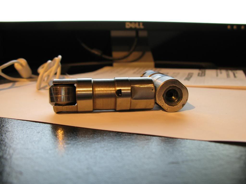
The tools used were purchased from Lindy Tool Company. The tool installs into the valve guide just as a valve would. Instead of a valve head, there is a cutting head. You set the cut depth, attach a drill and cut till it hits the depth stop collar. I will have in depth explanation on all of this with pictures as I progress.
To be on the safe side, I obtained a scrap head (thanks BES_Stroked_Nova). This prevents me from damaging the valve guides in my good set of heads. The heads I'm installing are PRC Stg. 2.5 5.3l heads, GM casting number XXX. The sprap head casting number is a GM 706, which is alos a 5.3l head. To be sure the heads would serve as an appropiate guide I measured valve angle, and a few other things.
Now, my good PRC heads have been milled down to a 59cc combustion chamber, and the junk heads are of unknown milling status. To maintain proper geometry, I need the centerline axis of the valve to be co-linear between the heads. Here is how I have done so.
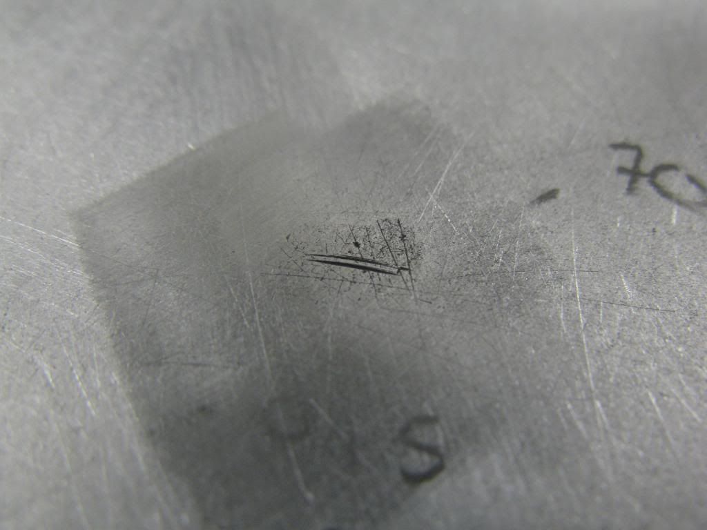
I made a fixture to hold both heads (the good one and the junk one) in the same location in respect to the alignment dowels. I installed the junk head with the new valves onto the fixture. When doing this procedure you must use the same set of valves on both heads. Then I pushed on the valve until it hit the aluminum plate. I spun the valve by hand, sort of grinding the edge of the valve into the aluminum. This made score in the aluminum. I did that for alll 8 valves. Then I put on the good head on did the same thing. If the centerline of the valve guides were co-linear then the marks would be in the same exact spot. As suspected, they were not in the same location.
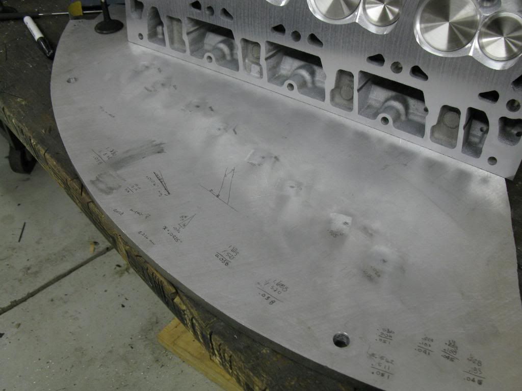
To have accurately located flycuts in the piston I need the valves in the both heads to contact in the same spot. Now I must determine how much needs to be milled off of the junk head. To do this I employed two techniques, and used them as a reality check to make sure they both agree.
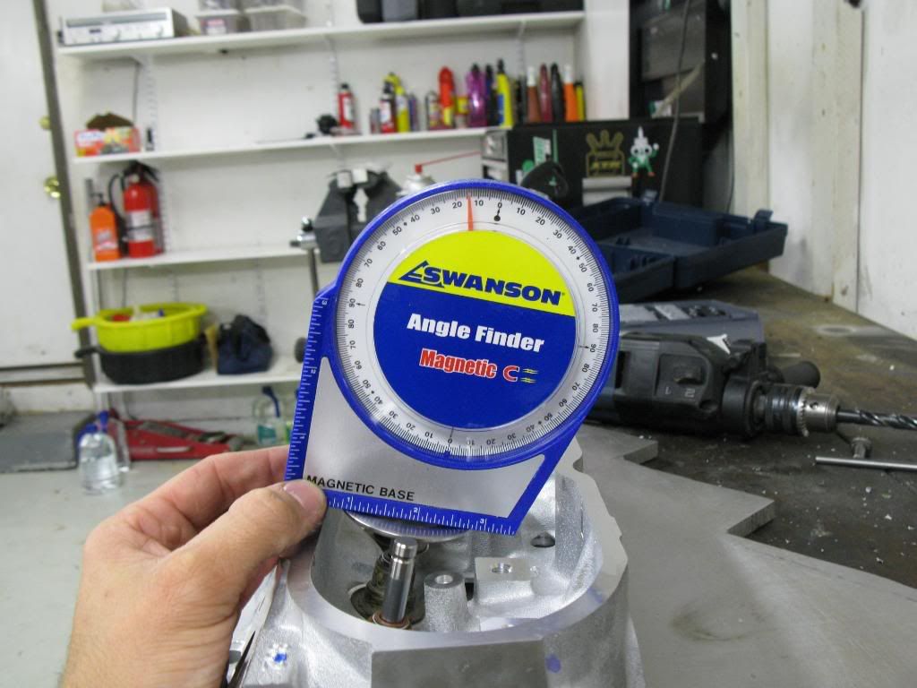
1. First I measured the distance between the two marks for each valve. Then I averaged them. I came up with an average of 0.0102" for all 8 valves. Then I measured the vavle angle to be 14 degrees. Knowing the distance between the two marks, and the valve angle I can determine the amount to be milled off of the junk head using some trig. I came up with 0.0409" to be milled off the junk head.
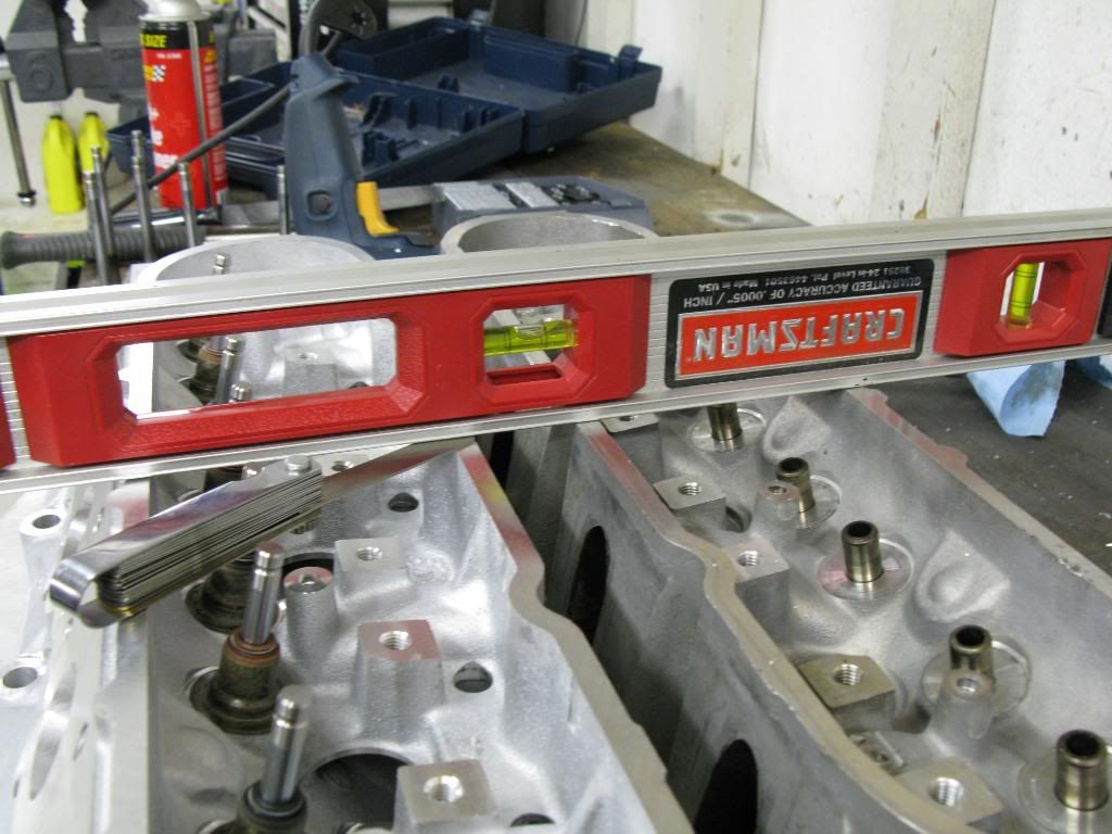
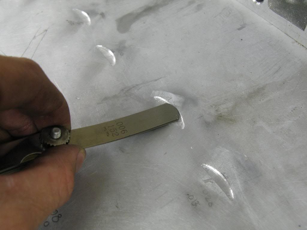
2. Second measurement was to put both heads on a flat surface, and put a straight edge across the top both heads. Using feeler gauges I measured the difference to be 0.037".
The two types of measurement differ by only ~0.003" so I'm satisfied that its correct. The more I think about it, the more I wonder how much different the answer would be if my measurement was off by 0.001" or 0.002", or my valve angle measurement was off by +/- 1 degree. If my measurement was off by 0.002 I could have an answer of 0.034". If I was off by angle, it could be 0.0388". Those very closely agree with my measured 0.037 height difference. Because of that I think I will mill off 0.035"
I will mill 0.035" becasue more milling would provide more clearance because only that side of the valve would contact the piston. In addition, the cutters have a 0.040" radial clearance for the valve. After i mill the head, I will reattach it to the fixture and make a new set of marks. The marks should be in the exact same spot as the PRC heads. If this is the case, I will proceed to the next step. I'll keep this thread updated as I go.
The idea here it to cut reliefs into the piston to obtain adaquate piston to valve (PTV) clearance.
The tools used were purchased from Lindy Tool Company. The tool installs into the valve guide just as a valve would. Instead of a valve head, there is a cutting head. You set the cut depth, attach a drill and cut till it hits the depth stop collar. I will have in depth explanation on all of this with pictures as I progress.
To be on the safe side, I obtained a scrap head (thanks BES_Stroked_Nova). This prevents me from damaging the valve guides in my good set of heads. The heads I'm installing are PRC Stg. 2.5 5.3l heads, GM casting number XXX. The sprap head casting number is a GM 706, which is alos a 5.3l head. To be sure the heads would serve as an appropiate guide I measured valve angle, and a few other things.
Now, my good PRC heads have been milled down to a 59cc combustion chamber, and the junk heads are of unknown milling status. To maintain proper geometry, I need the centerline axis of the valve to be co-linear between the heads. Here is how I have done so.
I made a fixture to hold both heads (the good one and the junk one) in the same location in respect to the alignment dowels. I installed the junk head with the new valves onto the fixture. When doing this procedure you must use the same set of valves on both heads. Then I pushed on the valve until it hit the aluminum plate. I spun the valve by hand, sort of grinding the edge of the valve into the aluminum. This made score in the aluminum. I did that for alll 8 valves. Then I put on the good head on did the same thing. If the centerline of the valve guides were co-linear then the marks would be in the same exact spot. As suspected, they were not in the same location.
To have accurately located flycuts in the piston I need the valves in the both heads to contact in the same spot. Now I must determine how much needs to be milled off of the junk head. To do this I employed two techniques, and used them as a reality check to make sure they both agree.
1. First I measured the distance between the two marks for each valve. Then I averaged them. I came up with an average of 0.0102" for all 8 valves. Then I measured the vavle angle to be 14 degrees. Knowing the distance between the two marks, and the valve angle I can determine the amount to be milled off of the junk head using some trig. I came up with 0.0409" to be milled off the junk head.
2. Second measurement was to put both heads on a flat surface, and put a straight edge across the top both heads. Using feeler gauges I measured the difference to be 0.037".
The two types of measurement differ by only ~0.003" so I'm satisfied that its correct. The more I think about it, the more I wonder how much different the answer would be if my measurement was off by 0.001" or 0.002", or my valve angle measurement was off by +/- 1 degree. If my measurement was off by 0.002 I could have an answer of 0.034". If I was off by angle, it could be 0.0388". Those very closely agree with my measured 0.037 height difference. Because of that I think I will mill off 0.035"
I will mill 0.035" becasue more milling would provide more clearance because only that side of the valve would contact the piston. In addition, the cutters have a 0.040" radial clearance for the valve. After i mill the head, I will reattach it to the fixture and make a new set of marks. The marks should be in the exact same spot as the PRC heads. If this is the case, I will proceed to the next step. I'll keep this thread updated as I go.
Last edited by Kevin Doe; Oct 21, 2008 at 08:36 AM.
Ok, scratch milling the junk head. I just got off the phone with Jason at Texas Speed. He said they mill 0.040 off the heads to get a 59cc chamber. So my measuring technique was pretty much right on. But, he did say that he does things a bit different. He uses an unmilled head, and no head gasket. On LS1s the piston comes out of the bore slightly. He suggested bolting the unmilled head on the block, and then rotating the piston around till it pushes up against the head. This will keep the piston in a positive position, and you don't need to worry about getting TDC, since ti will automatically be pretty much there. This will also keep the piston preloaded, and prevent it from rocking and chattering when cutting the reliefs. I think I'll use that method instead.
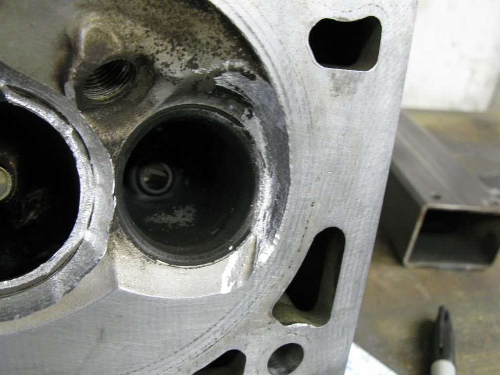
I started fooling wiht the flycutting a bit today. I test fit the cutters into the head and realized they dind't fit, so I had to do a bit of "deshrouding" with my carbide grinder to make them fit. Then I also realized that the intake cutter protruded past the surface of the head, so that wasn't gonna work. I cut out the valve seat and gringed the **** out of that area to make it fit. So much for using the Lindy tool on a good head. There may have been a better, or different way to amke it work but I didn't care since the head is junk anyhow.
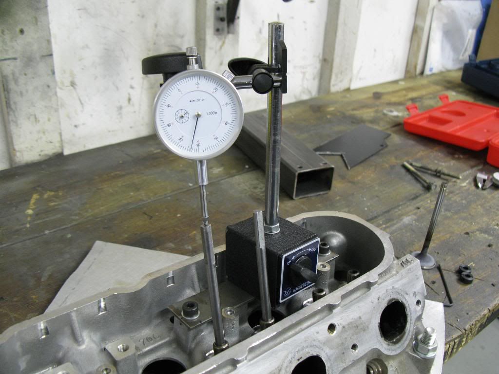
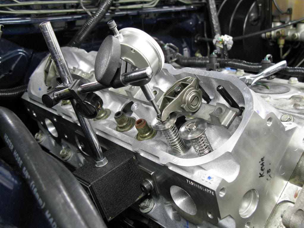
I had to make a ferrous plate to bolt in the head so my magnetic base dial gauge could stick to something.
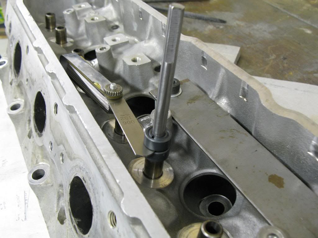
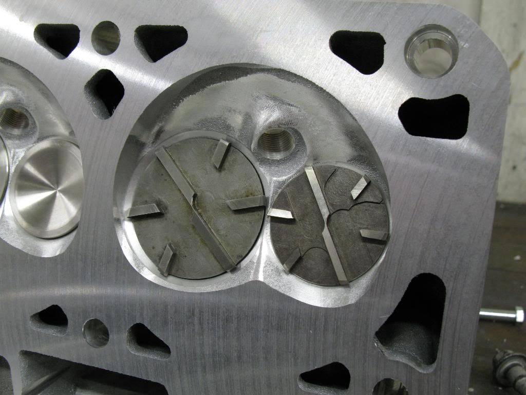
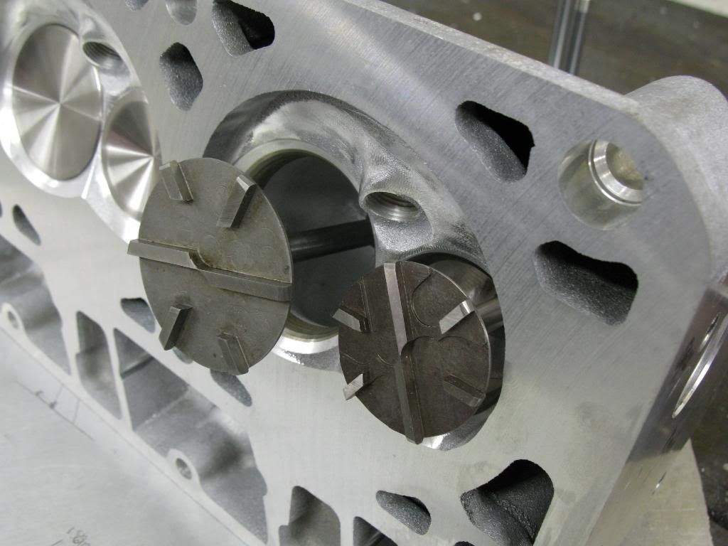
Then I installed the cutter, and used the dial gauge to determine the highest point on the cutter. Once I have the cutter at its highest point I can set the cutter depth. I used a tip form another forum member. Once the cutter was at its highest point I slid a collar down and snugged it. Then I slid another collar on. I put a stack of feeler gauges, 0.040" worth, between the collars. Then I tightened the **** out of the top collar. Then I removed the feeler gauges. Then I loosened the bottom collar so it would be snug, but still allow me to plunge the cutter down. This effectively limited my feed rate, and controlled the cutter better.
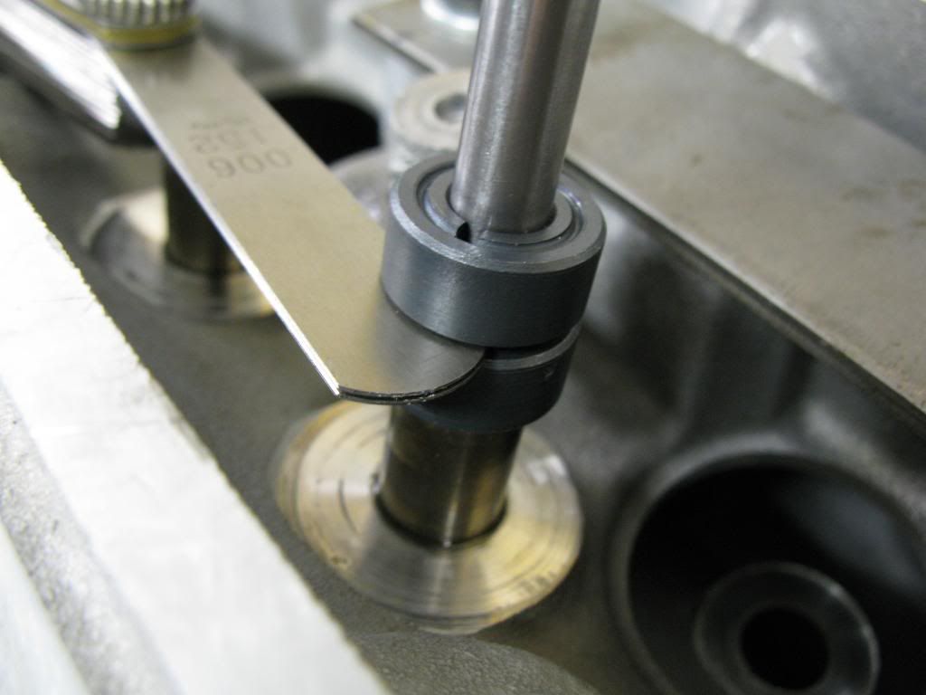
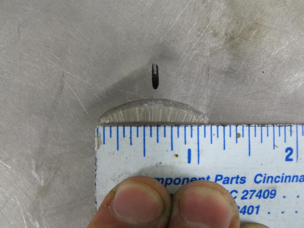
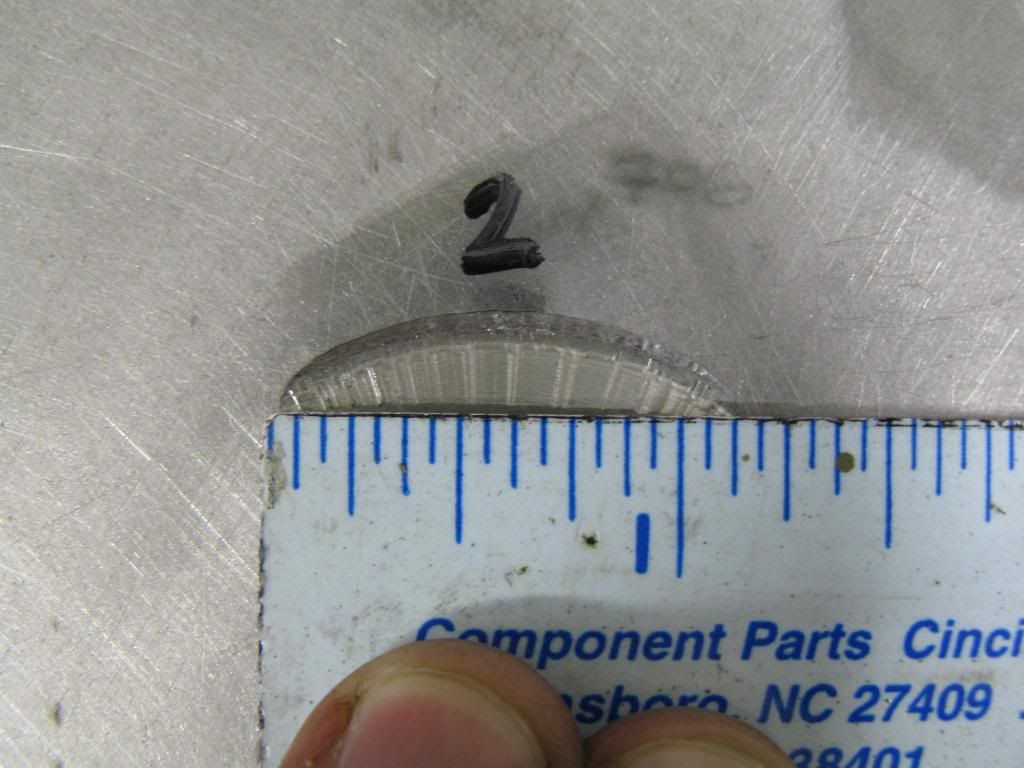
Then I made 4 practice cuts. I wanted to make sure I could consistantly cut the reliefs to a depth, and the depth that it cut was the depth I set. After I made the cuts I would check the depth with the feeler gauges. Another way to check is to measure the length of the cut. A small difference in depth would show up as a difference in cut width. I used both methods to make sure the cuts were consistant.
I had to make a ferrous plate to bolt in the head so my magnetic base dial gauge could stick to something.
Then I installed the cutter, and used the dial gauge to determine the highest point on the cutter. Once I have the cutter at its highest point I can set the cutter depth. I used a tip form another forum member. Once the cutter was at its highest point I slid a collar down and snugged it. Then I slid another collar on. I put a stack of feeler gauges, 0.040" worth, between the collars. Then I tightened the **** out of the top collar. Then I removed the feeler gauges. Then I loosened the bottom collar so it would be snug, but still allow me to plunge the cutter down. This effectively limited my feed rate, and controlled the cutter better.
Then I made 4 practice cuts. I wanted to make sure I could consistantly cut the reliefs to a depth, and the depth that it cut was the depth I set. After I made the cuts I would check the depth with the feeler gauges. Another way to check is to measure the length of the cut. A small difference in depth would show up as a difference in cut width. I used both methods to make sure the cuts were consistant.
I made some more practice cuts on the aluminum plate. I used an air drill and the results were much better. Significanly less chatter, and no chatter on a few cuts.
I checked the piston to valve clearance on the intake valve w/o any reliefs. 0.025". I have yet to check the exhasut PTVC, I'll do that one tomorrow.
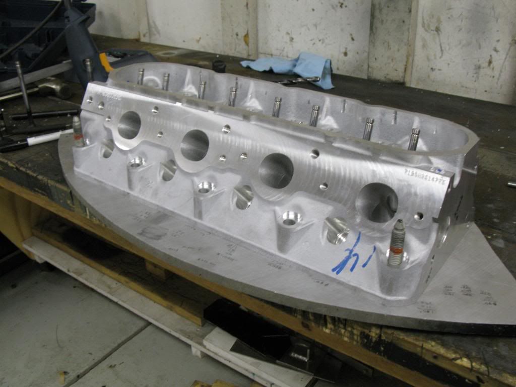
Here was the setup I used.
I have the MS4 cam on a stock bottom end LS1. LS7 lifters, GM MLS headgasket, PRC 2.5 5.3l heads with 59cc chambers (milled 0.040"). I'm shooting for 0.080" PTVC, so I suppose I'll make my intake cuts 0.060" deep. That should give me an 0.085" PTVC on the intake. I suppose that gives me an allotment of 0.005" for measurement error.
I checked the piston to valve clearance on the intake valve w/o any reliefs. 0.025". I have yet to check the exhasut PTVC, I'll do that one tomorrow.
Here was the setup I used.
I have the MS4 cam on a stock bottom end LS1. LS7 lifters, GM MLS headgasket, PRC 2.5 5.3l heads with 59cc chambers (milled 0.040"). I'm shooting for 0.080" PTVC, so I suppose I'll make my intake cuts 0.060" deep. That should give me an 0.085" PTVC on the intake. I suppose that gives me an allotment of 0.005" for measurement error.
So since I'm a novice I messed up the measurement on the PTVC. I was rotating the motor CCW when I was checking, and not CW. I also did not have all the lash adjusted out of the pushrods with the length checker. All those things fixed I measured:
0.004" clearance on the intake valve.
0.000" clearance on the exhaust valve. Aka, contact.
0.004" clearance on the intake valve.
0.000" clearance on the exhaust valve. Aka, contact.
0.000" clearance on the exhaust valve. Aka, contact.
You have a killer write up, but you're making things a little too hard on yourself. When I cut pistons, I use a junk 98 head, determine how deep of a relief I need based on my heads/cam specs, set the depth I want on my stop collar, and cut away till it hits my desired depth. Throw a light coat of grease on the piston to catch the shavings, makes cleanup easier and prevents shavings from getting down inside the motor.
Let us know how it works out.
Trending Topics
Be careful with that. It doesn't take much to bend a valve, even slightly.
You have a killer write up, but you're making things a little too hard on yourself. When I cut pistons, I use a junk 98 head, determine how deep of a relief I need based on my heads/cam specs, set the depth I want on my stop collar, and cut away till it hits my desired depth. Throw a light coat of grease on the piston to catch the shavings, makes cleanup easier and prevents shavings from getting down inside the motor.
Let us know how it works out.
I was unsatisified that my method of checking PTV clearance was adaquate using the hydraulic lifters (even with the light check spring), so I just modified two stock lifters. I welded the lifters up solid. New PTVC numbers tomorrow....
LS1 Tech Stories
The Best V8 Stories One Small Block at Time

6 Common C5 Corvette Failures and What's Involved In Repairing Them
Pouria Savadkouei
Retro Modern Bandit Pontiac Trans AM Comes With Burt Reynolds' Autograph
Verdad Gallardo
Top 10 Greatest Cadillac V Series Performance Models Ever, Ranked
Pouria Savadkouei
Top 10 Most Powerful Chevy Trucks Ever Made!

Hennessey's New Supercharged Silverado ZR2 Has 700 HP
Verdad Gallardo
Coachbuilt N2A Anteros Is an LS2-Powered C6 Corvette In Italian Clothes
Verdad Gallardo
Awesome K5 Blazer Restomod Comes With C7 Corvette Power
Verdad Gallardo
10 Camaros You Should Never Buy

10 LS Engine Myths That Refuse to Die
Verdad Gallardo
So you're saying you don't actually check PTV clearance on the actual motor? You just go by the nominal specs?
In your case, I retract my previous statement and I would agree you're doing the right thing. With that size cam and .040 cut off the heads, it's probably best to check current PTV first (which is probably zero right now
I put the modified solid lifters in today and remeasured the clearances. I came up with 0.003" intake, and 0.001" exhaust. Then I realized I made a mistake when I was removing the exhaust rocker. I used the same length pushrod (on the adjustable checker) for both intake and exhaust measurements. I then double checked the PR lengths required. The exhaust pushrod needed to be 3/4 of a turn shorter than the intake pushrod, which equates to ~0.0375" difference. That meant that when I measured the clearance on the exhaust valve the valve was 0.037 more closed than it should have been.
So I rechecked, each clearance, making sure to have zero lash and the appropiate pushrod length for each.
I remeasured and got these numbers. The new exhaust number reflects exactly the difference in pushrod length.
Intake: 0.003"
Exhaust: 0.038"
I know if you read through this thread you'll see that I measured about 58 times, and came up with a different result each time. I feel pretty confident that I measured correctly this time. I checked with the dial indicator, and then also with feeler gauges between the valve tip and rocker. Another thing worth noting when measuring is that the tightest intake clearance it occurs as the cam is ramping up in its profile, while the tightest exhaust clearance occurs when the cam is ramping down. Because of that, you have to ensure the lifter is seated up against the cam, and not sticking in the lifter trays. With only a test spring on the valve, it could stick and you would not know. Each time I'd measure I'd push down on the rocker to amke sure the lifter was up against the cam.
Given my results to maintain 0.080" clearance on the intake side, and 0.100" clearance on the exhaust side I would have to cut:
Intake cut: 0.077"
Exhaust cut: 0.062"
Given that I may end up cutting 0.080" on the intake, and 0.065" on the exhaust side.
Last edited by Kevin Doe; Oct 29, 2008 at 04:28 PM.

So I finally made my first cuts. I cut 0.080" on the intake, and 0.065" on the exhaust. That should have given me 0.083" PTVC and 0.103" PTVC respectively. After I made the cuts I measured and came up wiht 0.080" PTVC, and 0.097" PTVC. Looks like there is some spring in the material as it cuts or something. Close enough for government work.
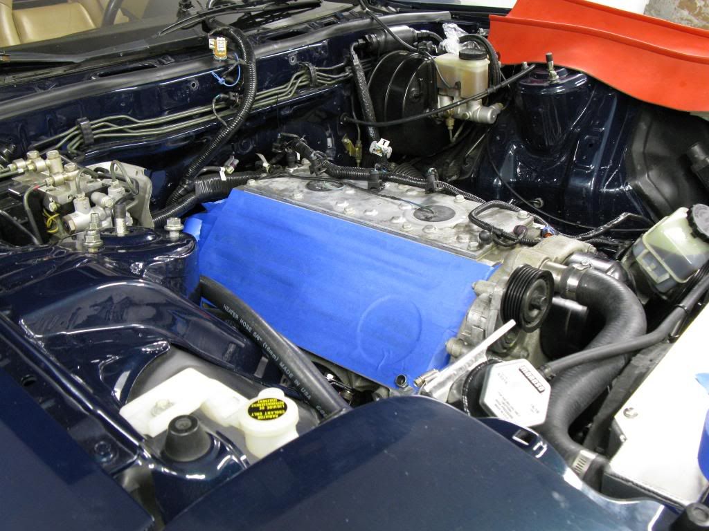
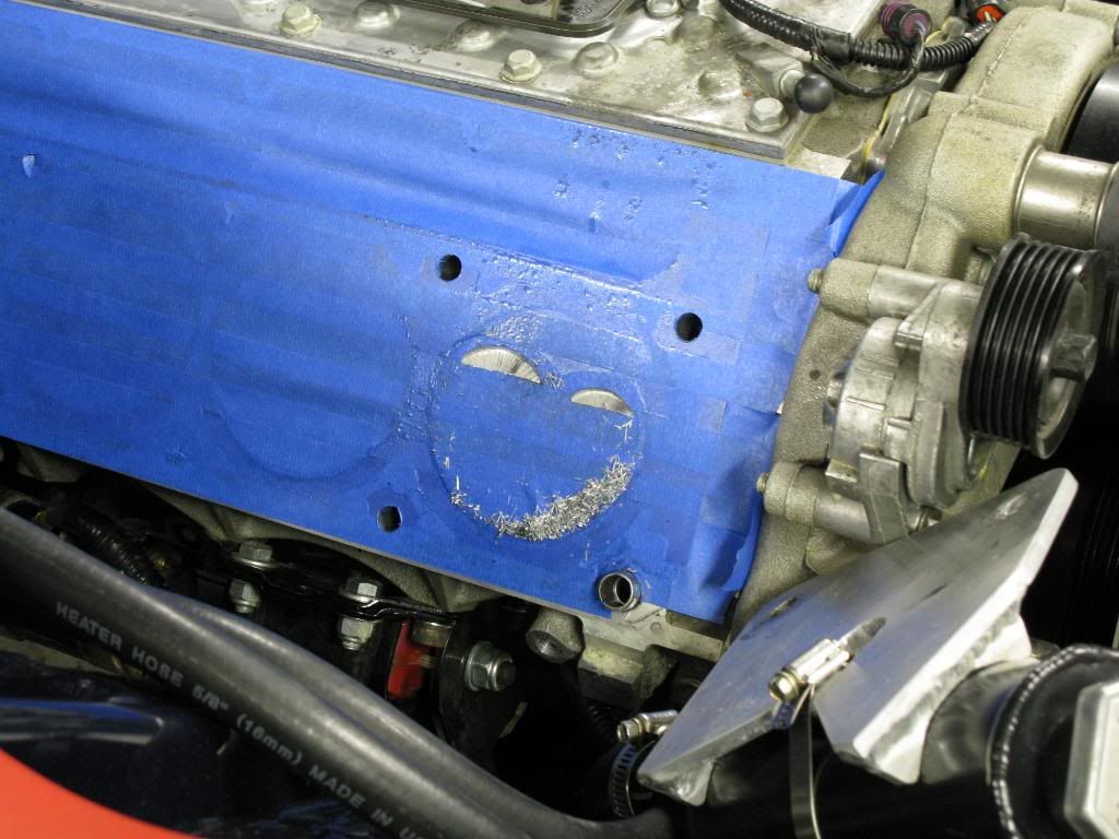
Here is the area all prepped for cutting. All taped off to ensure no metal chips get anywhere unwanted.
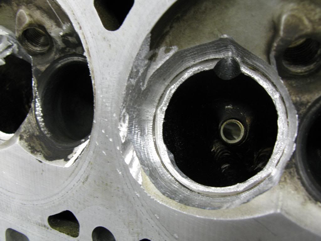
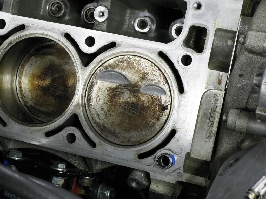
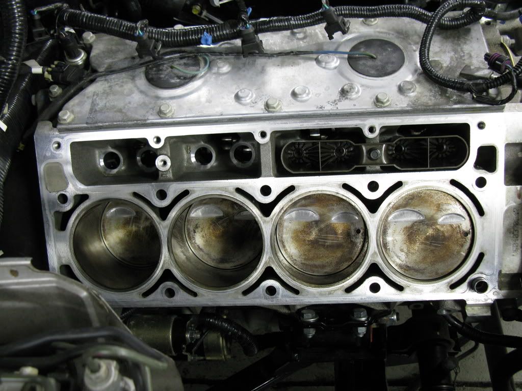
Made the intake and exhaust cuts on one cylinder. This pic is what it looks like when you pull the head off. You can see some chatter in the cuts, but its not too bad.
After I brushed away the shavings I sanded the edges down with some 200 grit sand paper. Finished product.
All its well, clearances are what they should be. Looks like its time to repeat 7 more times!
Here is the area all prepped for cutting. All taped off to ensure no metal chips get anywhere unwanted.
Made the intake and exhaust cuts on one cylinder. This pic is what it looks like when you pull the head off. You can see some chatter in the cuts, but its not too bad.
After I brushed away the shavings I sanded the edges down with some 200 grit sand paper. Finished product.
All its well, clearances are what they should be. Looks like its time to repeat 7 more times!


Staging Lane
Joined: Nov 2001
Posts: 69
Likes: 0
From: Ft. Lauderdale, FL
Great thread, thanks.
From picture above, it appears that you did the cuts with the piston a little down in the bore...is that true or is that just the way the picture appears? I understand the PTV contact happens a little down in the bore, but I'm wondering how you measured how far down to go when you made your cuts...if indeed you did that.
From picture above, it appears that you did the cuts with the piston a little down in the bore...is that true or is that just the way the picture appears? I understand the PTV contact happens a little down in the bore, but I'm wondering how you measured how far down to go when you made your cuts...if indeed you did that.