


cam bearing install cluster****

Thread Starter
TECH Apprentice
iTrader: (25)
Joined: Feb 2007
Posts: 370
Likes: 6
From: Morristown, Tn
So I'm rebuilding my 04 LS6.
First I bought a set of cam bearings from my parts supplier, durabond CHP10. I ASSume that these are correct and go to install them. Turns out that 04 blocks are apparently different from all the other 97-03 gen III blocks and actually use a different set of cam bearings that are a few thousandths different. Since I had already installed one of them I can't return/exchange them.
So I call up and order more of the correct cam bearings, supposed to be durabond CHP23. So finally they show up, and they sent me Mahle/Clevite Sh-2125S. This time (I think) I'm smart enough to measure their OD versus my original GM cam bearings. The new bearings are all about 4-5 thou bigger than the old ones on the OD, but I figure that's the crush factor. So once again I ASSume that these are correct and go to install them. Now I find that they are TIGHT as heck when pressed into place, so tight in fact that they lock onto my press tool once pressed into the bore. So I have to press them back out. I tried two of them.
Now I do more research and find that Clevite SH-2125S is actually for 08-09 GenIV blocks. WTF!
So I get fed up with this BS and call my friend at the dealer parts department. So he tells me that his computer shows 3 different possibilities for cam bearings for an 04 engine. Since my engine was obtained secondhand and I have no VIN to give him, he can't nail it down exactly. I offer to give him the block number and he says he can't look it up by that. We eliminated the 55mm bore size. He thinks he has the right set pulled up, and GM has discontinued one of the part numbers (I think for bearings 1 and 5) and the new part number is not showing up for him (or something). So he messes around and says he thinks he can put a call out to other dealers for that old part number and collect ones they may have on their shelves, and this will take a week or two. I tell him to get me two sets if he can, just so I don't have to deal with this in the future.
Should it really be this f*&^%%( hard to get a simple set of cam bearings for one of these damn motors? Can anyone tell me for sure what cam bearing part numbers I need to buy?
Coming from the import crowd, I'd like to bitchslap the next guy who tells me how cheap and easy LS motors are to work on compared to imports. I'm going to have over a grand plus 4-6 weeks in a basic refresh because I can't get the right parts for my block and there are apparently no machine shops with LS-specific experience. All of the ones I've asked have been like "uh, yeah, I think we've done a couple of those..." and then when I ask them specific questions about clearances or parts availability they're just like "well, I'll just have to look in the book and see what I can find...". I caught one of them looking up crank journal specs in the clevite book under 5.7 350 SBC, and so I pulled up the LS1 spec list from this forum on my phone and showed him that they were different.
I'm so frustrated. This **** sucks.
Durabond CH-23. Buy them from a sponsor, someone who knows LS engines inside and out. Aaron at TSP, for example, would be able to get you squared away.
What are you using to install the cam bearings, a press? Usually, we use something like this...

What are you using to install the cam bearings, a press? Usually, we use something like this...
Thread Starter
TECH Apprentice
iTrader: (25)
Joined: Feb 2007
Posts: 370
Likes: 6
From: Morristown, Tn
I bought this tool. It's meant to be used with a hammer.


This is fine for removal, but I wasn't real comfortable hammering IN the new cam bearings, because the mandrel that holds/pushes the bearings is all metal, and it seemed to slightly damage the bearing. The metal shaft is far too long to allow use in a press.
So I got another 1" metal shaft and cut it into two segments that fit the centering cone and mandrel from the other tool, and they allow me to press the bearings in.
The end that you have the cam bearing on doesn't look like it would work very well. The other tools out there have several sizes of expandable collets and a much more pronounce ridge for the back of the bearing to seat against when being driven in.
It really is easy with better tooling. This usually takes me less than 30 minutes to do. Also, are you lining up the holes with the oil galleys?
It really is easy with better tooling. This usually takes me less than 30 minutes to do. Also, are you lining up the holes with the oil galleys?
Thread Starter
TECH Apprentice
iTrader: (25)
Joined: Feb 2007
Posts: 370
Likes: 6
From: Morristown, Tn
It really is easy with better tooling. This usually takes me less than 30 minutes to do. Also, are you lining up the holes with the oil galleys?
Yes, I am lining up the holes. There is no problem with the procedure, except that the damn bearings I'm being sold are not physically the correct size.
Trending Topics
On the one I made the head actually just bolts onto the handle - I faced both mating surfaces flat and center drilled. The head is counterbored and the bolt threads into the handle. It would be easy enough to bore out a feature for a light press fit onto the 1" handle if that's what you want.
Haven't had occasion to sell one yet but if you get me your block's cam bore sizes and your (installed) bearing sizes I could make you one if you'd like. Might take me a few days to get material and access to a machine though - not sure what kind of turnaround you're after on this.
Carry it to PM's if you're interested.
LS1 Tech Stories
The Best V8 Stories One Small Block at Time

6 Common C5 Corvette Failures and What's Involved In Repairing Them
Pouria Savadkouei
Retro Modern Bandit Pontiac Trans AM Comes With Burt Reynolds' Autograph
Verdad Gallardo
Top 10 Greatest Cadillac V Series Performance Models Ever, Ranked
Pouria Savadkouei
Top 10 Most Powerful Chevy Trucks Ever Made!

Hennessey's New Supercharged Silverado ZR2 Has 700 HP
Verdad Gallardo
Coachbuilt N2A Anteros Is an LS2-Powered C6 Corvette In Italian Clothes
Verdad Gallardo
Awesome K5 Blazer Restomod Comes With C7 Corvette Power
Verdad Gallardo
10 Camaros You Should Never Buy

10 LS Engine Myths That Refuse to Die
Verdad Gallardo Thread Starter
TECH Apprentice
iTrader: (25)
Joined: Feb 2007
Posts: 370
Likes: 6
From: Morristown, Tn
On the one I made the head actually just bolts onto the handle - I faced both mating surfaces flat and center drilled. The head is counterbored and the bolt threads into the handle. It would be easy enough to bore out a feature for a light press fit onto the 1" handle if that's what you want.
Haven't had occasion to sell one yet but if you get me your block's cam bore sizes and your (installed) bearing sizes I could make you one if you'd like. Might take me a few days to get material and access to a machine though - not sure what kind of turnaround you're after on this.
Carry it to PM's if you're interested.
Haven't had occasion to sell one yet but if you get me your block's cam bore sizes and your (installed) bearing sizes I could make you one if you'd like. Might take me a few days to get material and access to a machine though - not sure what kind of turnaround you're after on this.
Carry it to PM's if you're interested.
But, PM me a price range of what you'd want to make one for me, just for future use on the next motor.
Thread Starter
TECH Apprentice
iTrader: (25)
Joined: Feb 2007
Posts: 370
Likes: 6
From: Morristown, Tn
My part supplier swears that the clevite bearings they sent me are correct for my year, even though summit racing's application list only shows it for GenIV engines. However I finally found Clevite's catalog and sure enough, it lists this bearing set for 2003-2010 LS engines including the LS6. So I figure these must be right for my engine, and the issues I'm having are maybe normal things that you have to do during an engine build?
So...to the experienced engine builders of the forum...
Is it common/normal to have to hand clearance your cam bearings? I was more under the impression that you simply pressed them in and were good to go.
All the cam journals spec out perfectly. The press tool diameter is identical to the cam journal spec.
When I press in a new cam bearing, it gets tight on the press tool. I basically have to tap it out from below/behind to get it to move out of the bearing. Once it comes out, there is no real damage to the bearing, but you can see a shiny spot where the bearing high spots are.
I have done bearings 3, 2, and 1 so far, and each of them has had high/tight spots at the oiling holes and at the top. I have been using very fine #0000 steel mesh wool to clearance the bearings. Then I slide the cam in and out until it doesn't leave much of a shiny spot on the bearing anymore.
So far the cam slides in and out well, and spins like butter.
My main goal here is to find out if it's normal and okay to be hand clearancing the bearings like this.
In my experience, the bearings always go in tight. I use a Sunnen cam bearing tool with an expandable collet in a rubber sleeve. The bearing slides over the collet and the drivers threads into it. The more you thread the driver into the collet, the more the collet expands in the bearing. It has a good step behind it to drive the bearing in, so it's not using the force of the collet on the ID of the bearing to drive it in. Once it's in, I loosen the collet and it comes right out. I check the oil hole alignment with a mirror and move on to the next one if its good.
As far as clearance, I have seen it get tight. My engine had .0005" clearance on a couple of the journals, so I took it to a local crank grinder and had him turn it .002". I'm not okay with taking scotchbrite or steel wool to the surface of a bearing, so that's why I turned the cam. Some people are okay with that, so they'll spend hours clearancing the bearings and ignore the risks associated with imbedding all that crap into the bearing surface.
As far as clearance, I have seen it get tight. My engine had .0005" clearance on a couple of the journals, so I took it to a local crank grinder and had him turn it .002". I'm not okay with taking scotchbrite or steel wool to the surface of a bearing, so that's why I turned the cam. Some people are okay with that, so they'll spend hours clearancing the bearings and ignore the risks associated with imbedding all that crap into the bearing surface.
Thread Starter
TECH Apprentice
iTrader: (25)
Joined: Feb 2007
Posts: 370
Likes: 6
From: Morristown, Tn
UPDATE:
I had previously installed the clevite cam bearings 1, 2, and 3. Each time I would install a bearing, it would lock down on the tool and I'd have to force the tool out of the bearing, scratching up the bearing surface. I found that there were extreme high/tight spots at all of the drilled oil holes, and at 12 oclock on each of those bearings. I used fine steel wool to hand clearance those areas and try to take off the high spots. The actual cam would go in and spin pretty freely by hand after doing the hand clearancing.
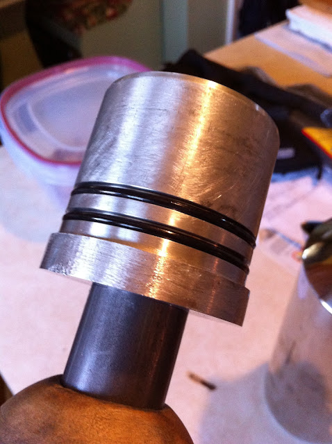
ckpitt55 was nice enough to modify my carshop cam install tool mandrel by turning it down and installing two o-rings to try and prevent metal to metal contact with the bearings and keep the cam bearings from crushing down and locking onto the tool once pressed into the block bores.

I got it today and couldn't wait to try it out.
I installed bearing 4, the modified tool came out of the installed bearing like BUTTER, and then test fit the cam. The cam would not even slide into bearing 4 at all. Pressed 4 back out. Extreme high spots by both oil holes. I had a second set of identical cam bearings so I pressed in a second one. The cam would at least slide into that one, but was still really tight. More hand clearancing around the oil holes to get the cam to slide in and spin freely.
Number 5 went right in and the cam spun very well. Still had to do some clearancing of the high spots at the oil holes but not half as much as 4.
So at this point the cam goes in and spins pretty freely by hand. I go in and out a few more times and continue to touch up the remaining high spots.
Eventually I get it about as good as I think I can, cam slides right in and spins like butter by hand, and I check the actual clearances with feeler gauges by sliding them in at the top of the cam journal. 1 and 5 give me 1.5-2 thou. 2, 3, and 4 I can't get my 1.5 thou feeler in without forcing.
I go to check the clearance spec on my printout from the forum and to my surprise there is not even a clearance spec listed for the cam. I've read that some guys "guess" or "think" "about .003" is what you're supposed to have.
So, how are you supposed to GET that much clearance if you don't have it? Is a machine shop supposed to line bore the installed cam bearings to gain perfect clearance and round?
I'm here trying to find the guy who has done this more than once and knows exactly how it is "supposed to be", what is normal and what is not, and not so much the guy who is like "well, when I did my 1 build, I did it this way and it seems okay so far...". I want to know the correct answer, both for this build and my future knowledge for other potential builds. Someone throw me a bone here.
I had previously installed the clevite cam bearings 1, 2, and 3. Each time I would install a bearing, it would lock down on the tool and I'd have to force the tool out of the bearing, scratching up the bearing surface. I found that there were extreme high/tight spots at all of the drilled oil holes, and at 12 oclock on each of those bearings. I used fine steel wool to hand clearance those areas and try to take off the high spots. The actual cam would go in and spin pretty freely by hand after doing the hand clearancing.
ckpitt55 was nice enough to modify my carshop cam install tool mandrel by turning it down and installing two o-rings to try and prevent metal to metal contact with the bearings and keep the cam bearings from crushing down and locking onto the tool once pressed into the block bores.
I got it today and couldn't wait to try it out.
I installed bearing 4, the modified tool came out of the installed bearing like BUTTER, and then test fit the cam. The cam would not even slide into bearing 4 at all. Pressed 4 back out. Extreme high spots by both oil holes. I had a second set of identical cam bearings so I pressed in a second one. The cam would at least slide into that one, but was still really tight. More hand clearancing around the oil holes to get the cam to slide in and spin freely.
Number 5 went right in and the cam spun very well. Still had to do some clearancing of the high spots at the oil holes but not half as much as 4.
So at this point the cam goes in and spins pretty freely by hand. I go in and out a few more times and continue to touch up the remaining high spots.
Eventually I get it about as good as I think I can, cam slides right in and spins like butter by hand, and I check the actual clearances with feeler gauges by sliding them in at the top of the cam journal. 1 and 5 give me 1.5-2 thou. 2, 3, and 4 I can't get my 1.5 thou feeler in without forcing.
I go to check the clearance spec on my printout from the forum and to my surprise there is not even a clearance spec listed for the cam. I've read that some guys "guess" or "think" "about .003" is what you're supposed to have.
So, how are you supposed to GET that much clearance if you don't have it? Is a machine shop supposed to line bore the installed cam bearings to gain perfect clearance and round?
I'm here trying to find the guy who has done this more than once and knows exactly how it is "supposed to be", what is normal and what is not, and not so much the guy who is like "well, when I did my 1 build, I did it this way and it seems okay so far...". I want to know the correct answer, both for this build and my future knowledge for other potential builds. Someone throw me a bone here.
TECH Fanatic

Joined: Jun 2011
Posts: 1,343
Likes: 8
From: Katy, TX
see post #11, this is coming from a very well known LS engine builder.
https://ls1tech.com/forums/generatio...d-replace.html
I had the same issues as you - clearancing the bearings by hand to remove the high spots. I ended up with 0.006" clearance in some areas.
https://ls1tech.com/forums/generatio...d-replace.html
I had the same issues as you - clearancing the bearings by hand to remove the high spots. I ended up with 0.006" clearance in some areas.

So, how are you supposed to GET that much clearance if you don't have it? Is a machine shop supposed to line bore the installed cam bearings to gain perfect clearance and round?
I'm here trying to find the guy who has done this more than once and knows exactly how it is "supposed to be", what is normal and what is not, and not so much the guy who is like "well, when I did my 1 build, I did it this way and it seems okay so far...". I want to know the correct answer, both for this build and my future knowledge for other potential builds. Someone throw me a bone here.
I'm here trying to find the guy who has done this more than once and knows exactly how it is "supposed to be", what is normal and what is not, and not so much the guy who is like "well, when I did my 1 build, I did it this way and it seems okay so far...". I want to know the correct answer, both for this build and my future knowledge for other potential builds. Someone throw me a bone here.
Option B: decrease journal OD
Myself, as well as several other local shops prefer to grind the cam journals rather than take scotchbrite to a bearing. Others don't really care and will spend all day scratching on a bearing to get the cam to slide in, and when it's in, they usually call it good without concern as to what clearance it ended up with. I've had to do both and have seen both methods "work", however when I sleep at night I feel better that I didn't scotchbrite my bearings and that I knew what the clearances were.
glad to see the tool worked out for you
as Rezin suggested, how it "feels" i think is more important than adhering to hard clearances which is why there's such a wide tolerance window.
if you can, maybe check out your clearances with a mic and bore gauge. I'd have trouble trusting feeler gauges as my foundation for decision making.
as Rezin suggested, how it "feels" i think is more important than adhering to hard clearances which is why there's such a wide tolerance window.
if you can, maybe check out your clearances with a mic and bore gauge. I'd have trouble trusting feeler gauges as my foundation for decision making.
Thread Starter
TECH Apprentice
iTrader: (25)
Joined: Feb 2007
Posts: 370
Likes: 6
From: Morristown, Tn
I take a lot of pictures as part of my work, and I wear out digicams within a couple of years. They get to where the battery won't hold charge and they won't focus anymore , so I have to buy new ones.
Of course as time goes on, the specs of the digicams go up constantly.
The latest one is something like 15 megapixel (fujifilm). Stupid huge picture size, file size (data), and quality. Way too much for posting pics online. So rather than having spend time to try and edit EVERY pic I post online (thousands yearly) I go into the camera settings and try to turn the quality and size settings down. That usually works okay, but on this camera it doesn't.
I have selected the 3rd-to-lowest quality/size setting available on this camera for the pics. As you can see they come out kind of blurry and are still quite large.
However, if I step down to the next two settings of even lower quality to try and reduce the size further, the pics become so blurry that you can't even see any details and it looks like you took the picture through a ziploc baggie.
So the bottom line is, this setting is the best compromise between quality and picture size on this particular camera. As digicams aren't really cheap, I can't just run out and buy another new one (likely with even larger file sizes and picture sizes programmed) to suit the few remaining dudes on the internet still using a 15" CRT with a native resolution of 800x600.
I've even thought of trying to find one of the older style digicams (a couple of generations old, like a 5 megapixel) but the problem is they are not designed for long-term life and are all worn out or damaged by now.
Thread Starter
TECH Apprentice
iTrader: (25)
Joined: Feb 2007
Posts: 370
Likes: 6
From: Morristown, Tn
glad to see the tool worked out for you
as Rezin suggested, how it "feels" i think is more important than adhering to hard clearances which is why there's such a wide tolerance window.
if you can, maybe check out your clearances with a mic and bore gauge. I'd have trouble trusting feeler gauges as my foundation for decision making.
as Rezin suggested, how it "feels" i think is more important than adhering to hard clearances which is why there's such a wide tolerance window.
if you can, maybe check out your clearances with a mic and bore gauge. I'd have trouble trusting feeler gauges as my foundation for decision making.