


LM7 Build for my CJ7 Project

Thread Starter
Teching In
Joined: May 2014
Posts: 39
Likes: 1
I am currently working on a project to upgrade my 1979 Jeep CJ7, which I have owned for 28 years. It is definitely time to do some well deserved upgrades. My plans are to swap out the AMC 304 V8 and surgically install a rebuilt GM 5.3L LM7.
I rebuilt the current 304 back in 1994 and the experience was a lot of fun. I am using this opportunity to share this experience with my 2 sons (17 and 20).
Your not going to find massive upgrades and high tech features here. My plans are to rebuild this LM7 as a stock configuration except for a mild Cam upgrade to possibly help it sound like the upgrades that I made to the 304. This build will include a Comp Cam 408-11 upgrade along with the required heavier springs. But wait!!! It wouldn't make sense to tear this thing down and not refresh many of the wearable parts. So there are a ton of things that will be replaced.
The intention of this post is not to teach you how to do this, but rather show you the steps that I have taken so that you could decide if UCanDoIt2!
With the cheap cost of digital photography (free), I have taken tons of photos and have published detailed videos of the steps that I am taking.
Hope you enjoy the walk through!
Mike
Thread Starter
Teching In
Joined: May 2014
Posts: 39
Likes: 1
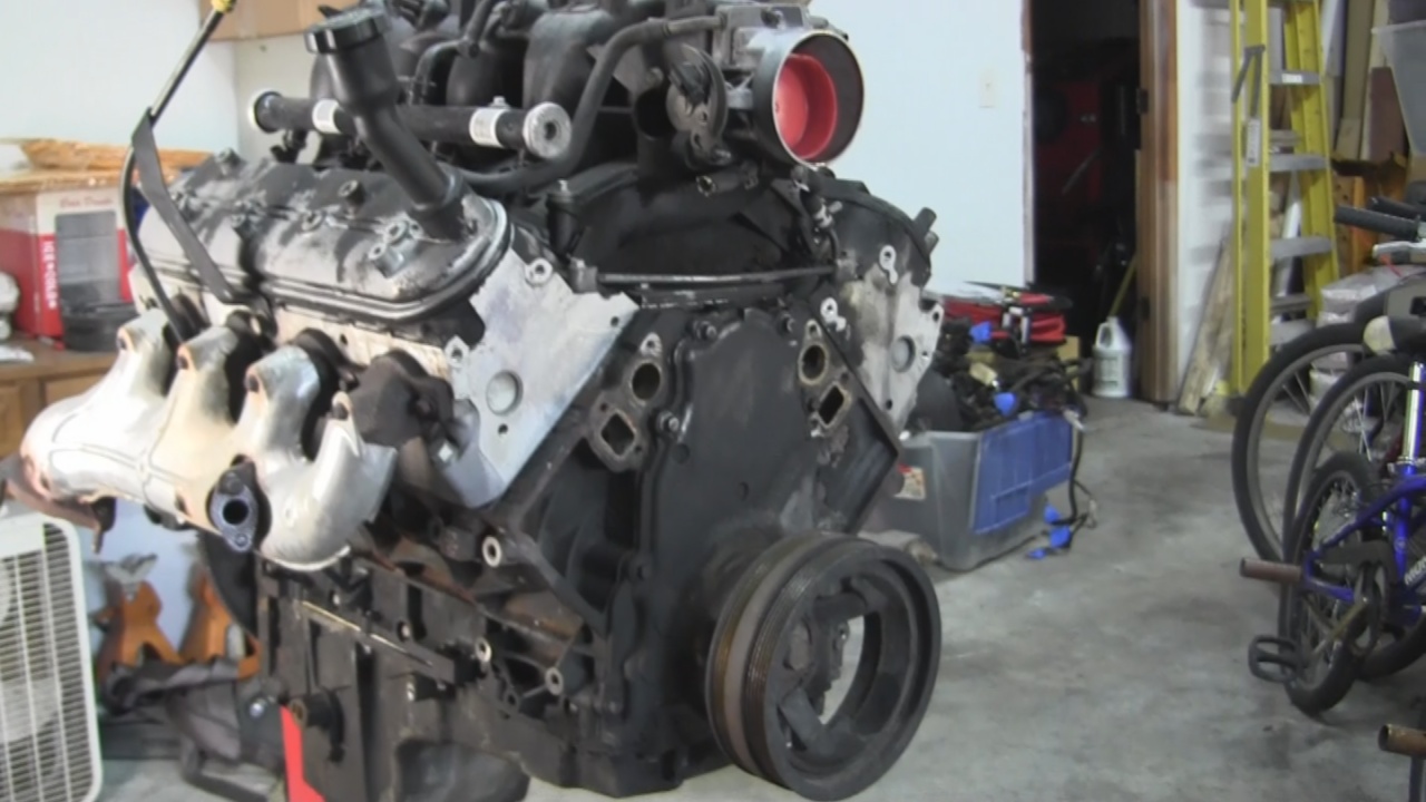
Things just got a little real! Picked up the new Engine. This is a GM 5.3L LM7 (VIN 8th digit "T") engine from a 2001 Chevy Silverado 1500.

This was a full pull and includes: Engine, Engine Wiring Harness, PCM, Complete Fuse Block, Flex Plate, Starter and Motor Mounts.
The next steps will be tearing this engine down for a complete rebuild. :2thumbsup:
This was a full pull and includes: Engine, Engine Wiring Harness, PCM, Complete Fuse Block, Flex Plate, Starter and Motor Mounts.
The next steps will be tearing this engine down for a complete rebuild. :2thumbsup:
Last edited by UcanDoIt2; May 8, 2017 at 10:32 PM.
Thread Starter
Teching In
Joined: May 2014
Posts: 39
Likes: 1
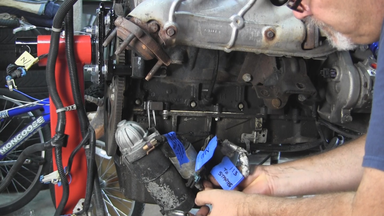
Was able to get the engine cherry picked out of the truck and onto an engine stand. We started to Label and Remove the Engine Harness.
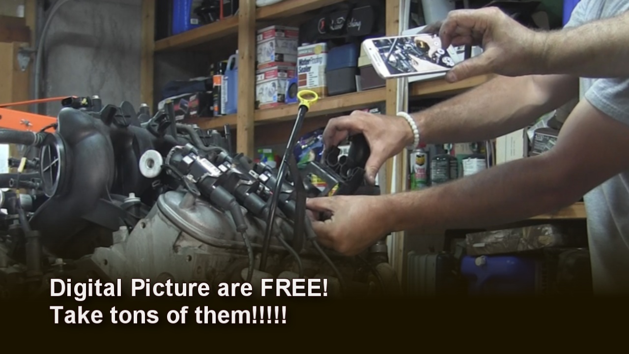
Here I am at the Starter and Crankshaft Position Sensor labeling and disconnecting.
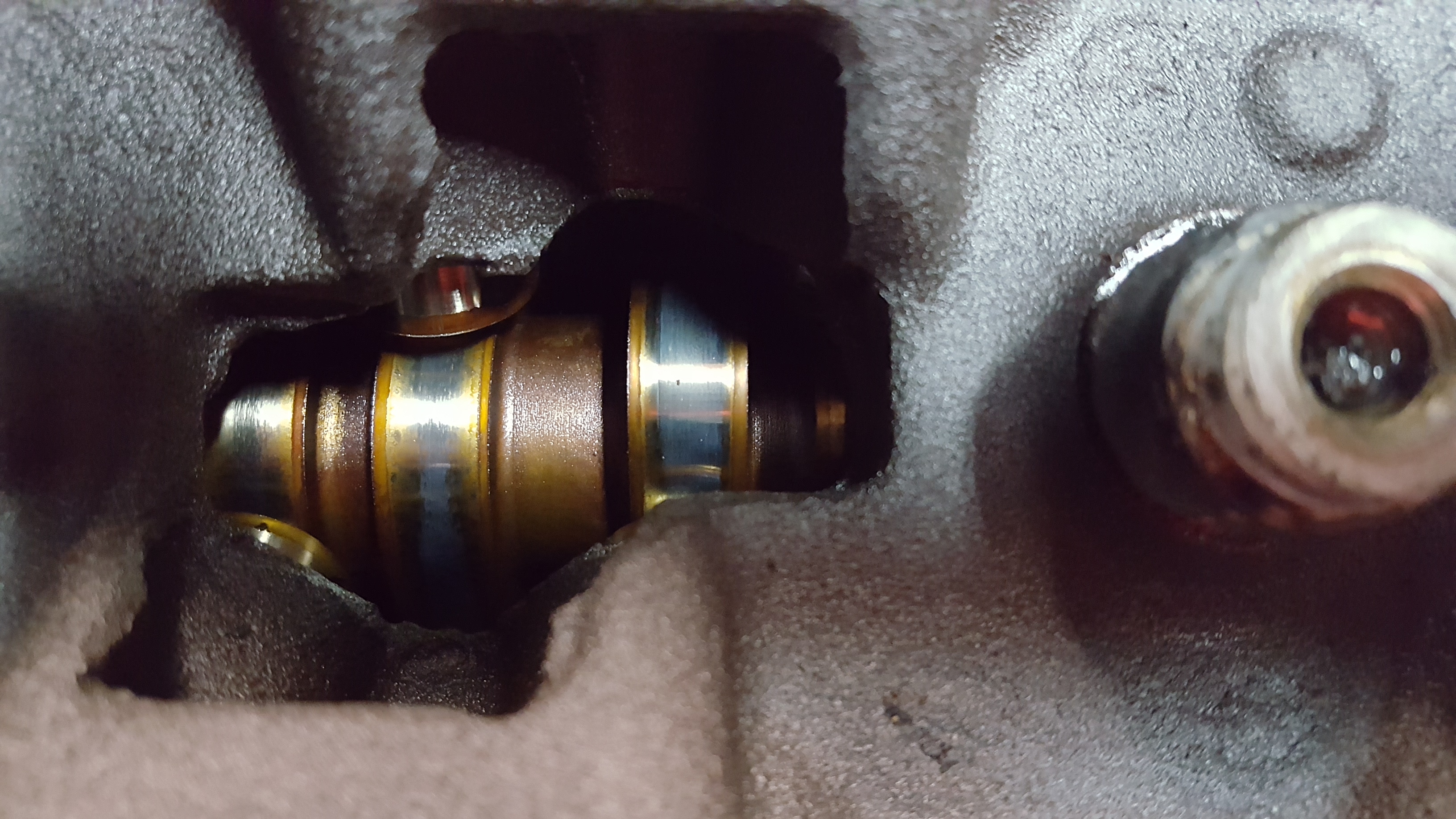
Just removed the Fuel Injectors and Coil Harness connections.
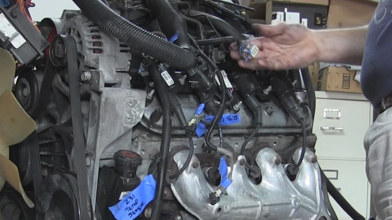
Working our way to the back along the top.
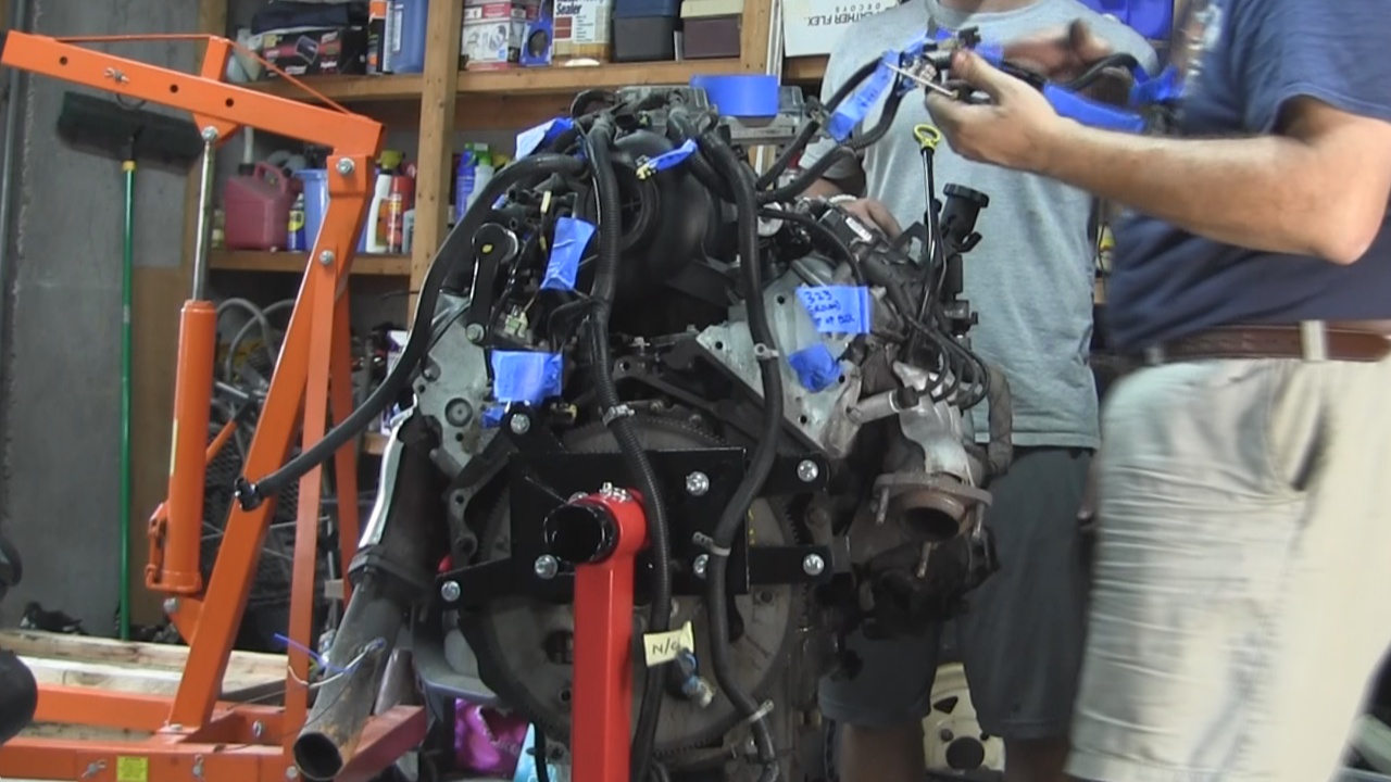
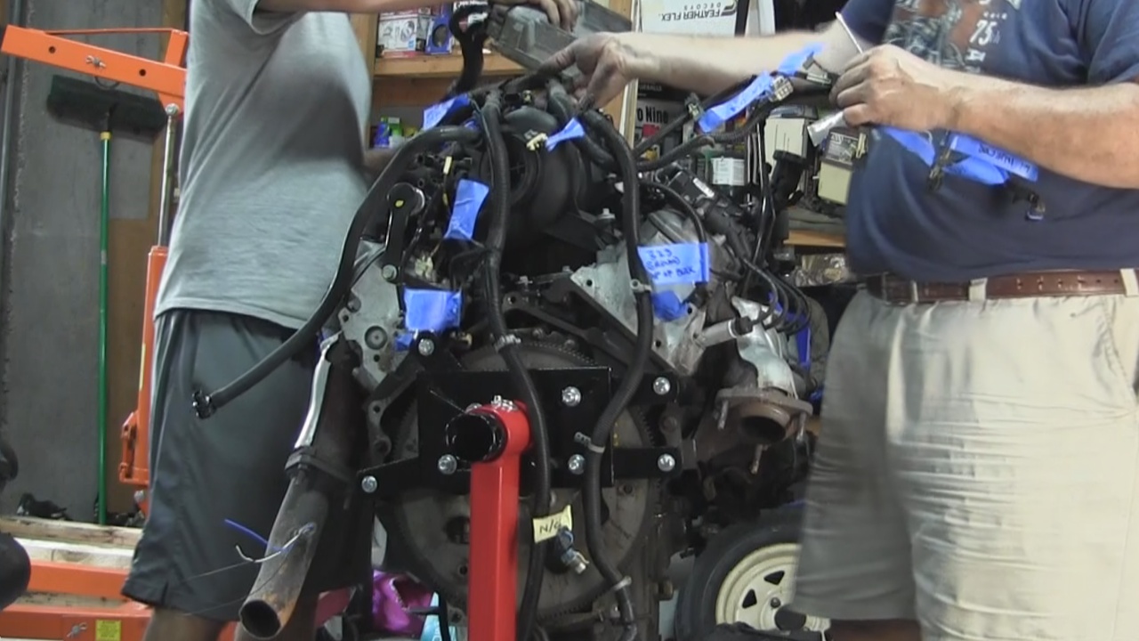
And finally getting to remove in bulk the harness.
Don't forget to take picture of any connection or situation that you feel would be helpful during the re-installation. Digital photography is Free.
After removing the Accessory belt, we took off the Alternator.
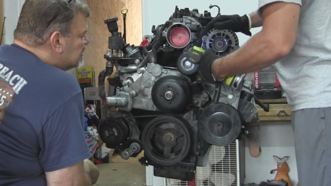
Removed the Alternator and Power Steering Bracket.
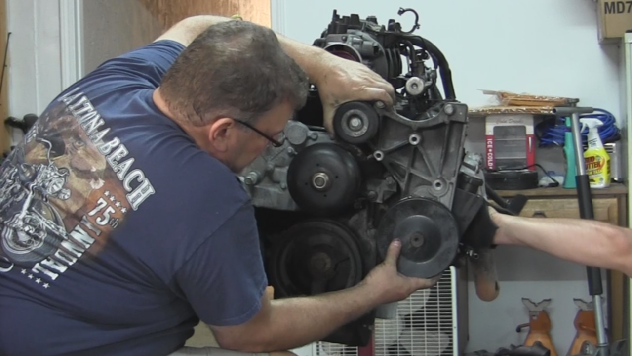
A/C Compressor and mounting bracket
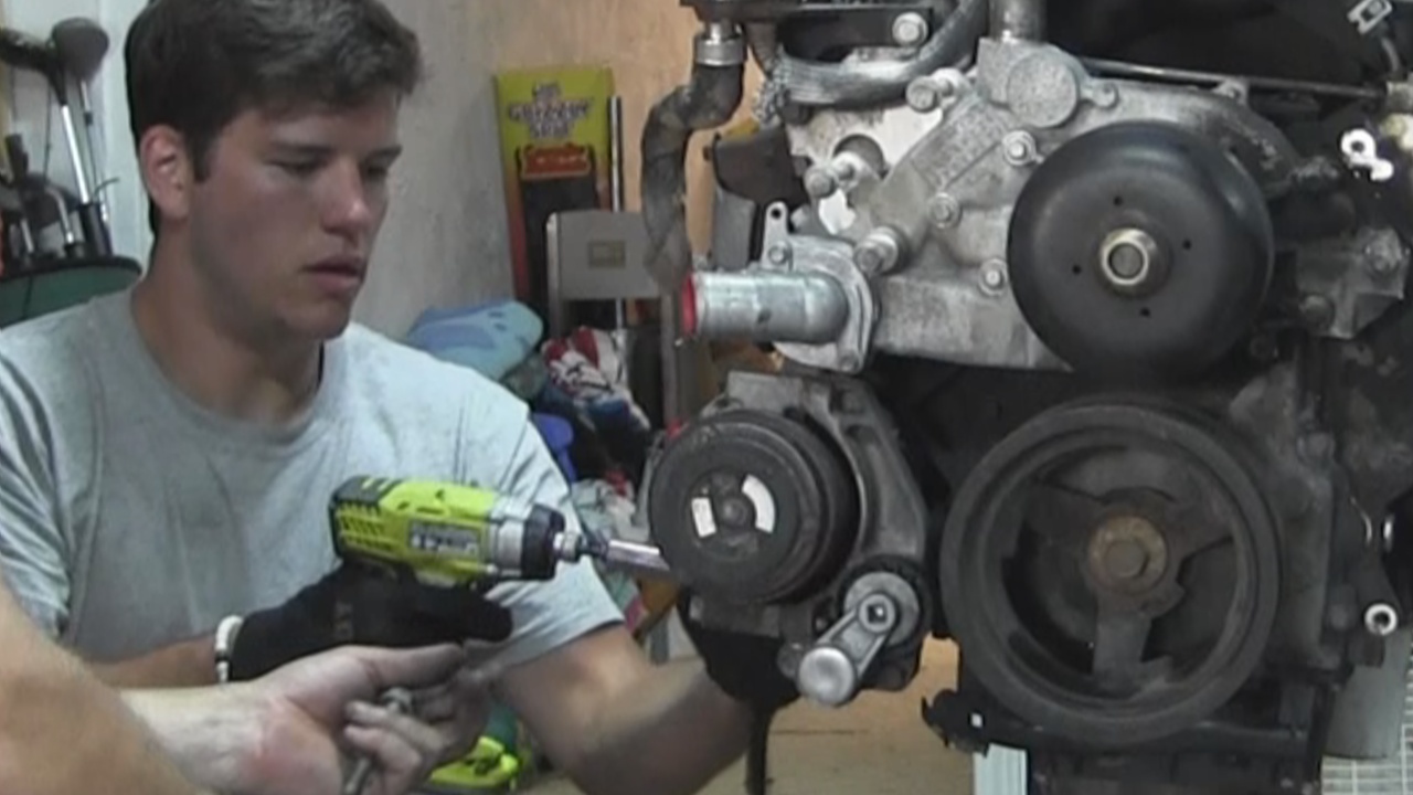
After removing the Water Pump, we had all of the accessories off the engine.
My oldest son helped me on this day. He really enjoys all of this. A great father/son project.
Here I am at the Starter and Crankshaft Position Sensor labeling and disconnecting.
Just removed the Fuel Injectors and Coil Harness connections.
Working our way to the back along the top.
And finally getting to remove in bulk the harness.
Don't forget to take picture of any connection or situation that you feel would be helpful during the re-installation. Digital photography is Free.
After removing the Accessory belt, we took off the Alternator.
Removed the Alternator and Power Steering Bracket.
A/C Compressor and mounting bracket
After removing the Water Pump, we had all of the accessories off the engine.
My oldest son helped me on this day. He really enjoys all of this. A great father/son project.
Last edited by UcanDoIt2; May 8, 2017 at 10:33 PM.
Thread Starter
Teching In
Joined: May 2014
Posts: 39
Likes: 1
Here is a detailed look at the initial removal of the external parts of the 5.3L rebuild project. This video covers Labeling/Removing the Wiring Harness, removing all of the Front Accessories, and a brief talk about the location of all of the Sensors.
Thread Starter
Teching In
Joined: May 2014
Posts: 39
Likes: 1
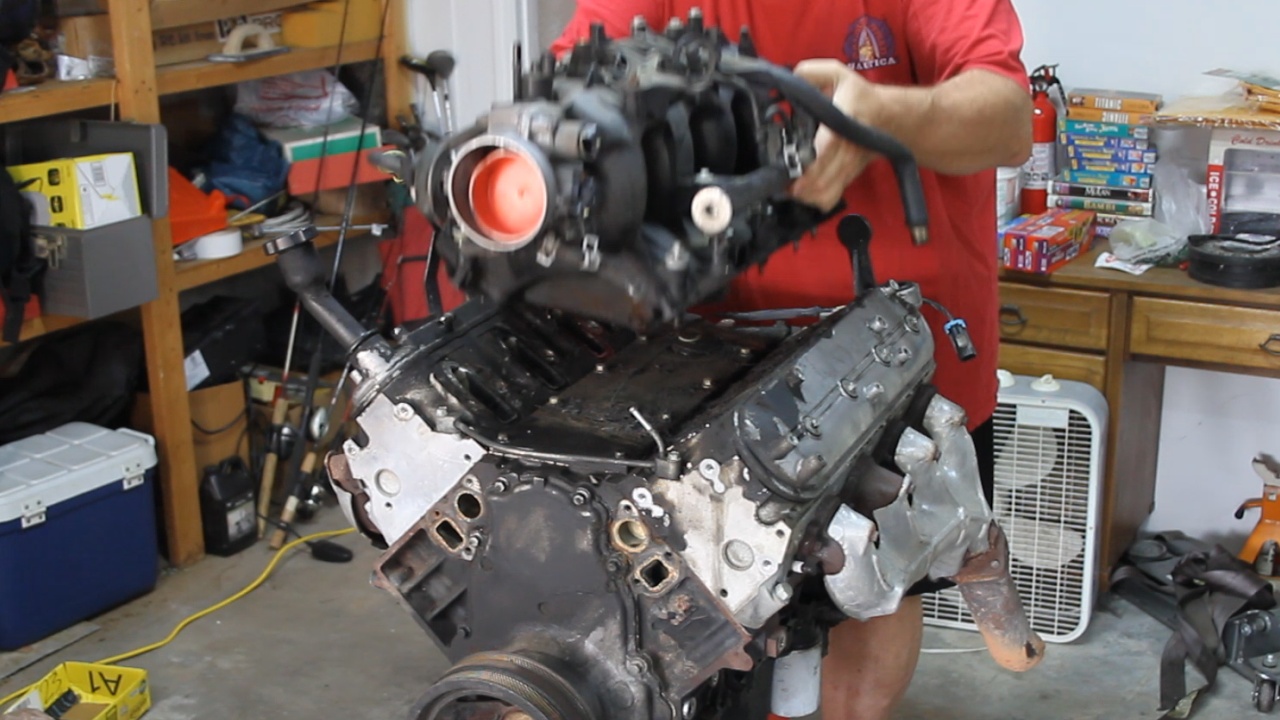
Worked on tearing down the top end of the 5.3L LM7. Again following the steps of a manual that I have and assigning the step numbers to all bolts and categorizing them in a bin. All the work started with removing the Intake.
Next we removed the Knock Sensors and Valley Pan
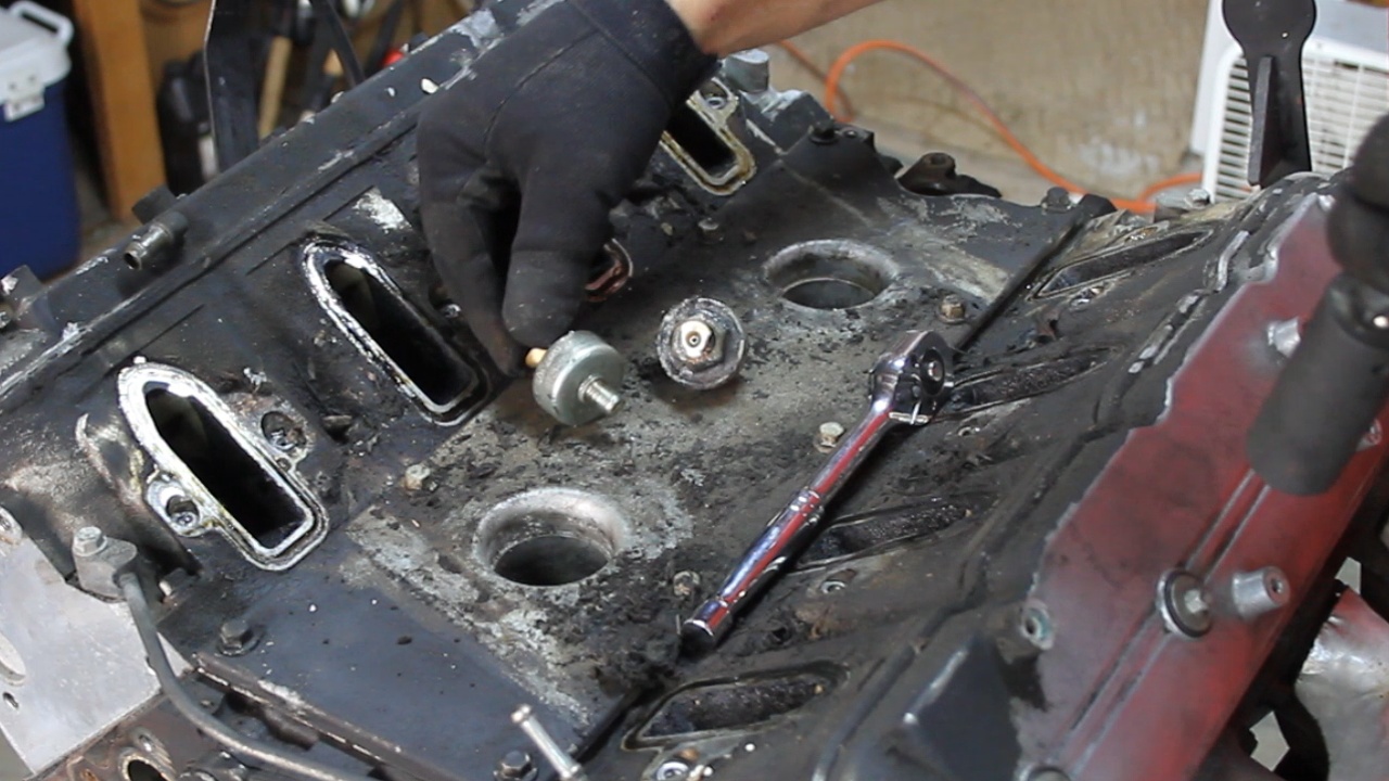
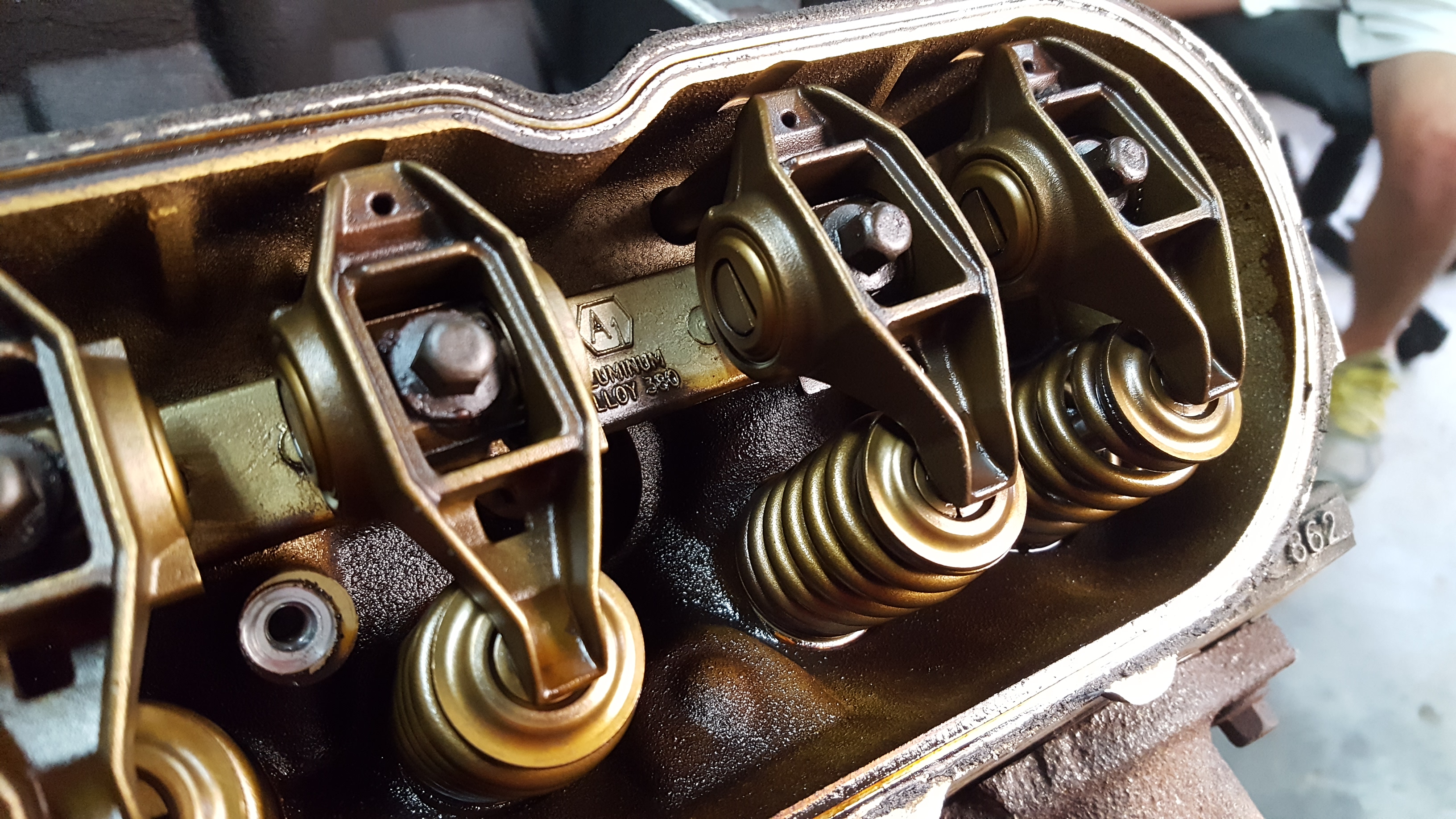
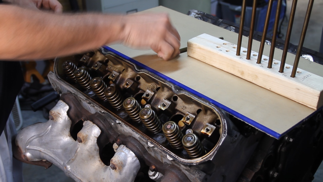
Next was the removal of the Valve Covers which gave us the first look at the Valve Train and Cam
Next, we removed the Rocker Arms and Push Rods.
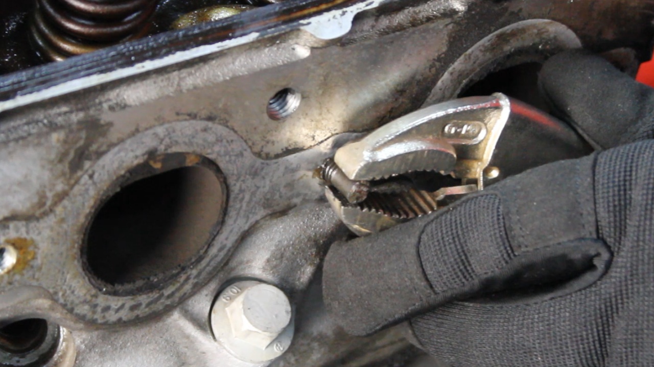
When removing the Exhaust Manifolds, we noticed that three of the bolts were broken off. I soaked what was left of the studs in Kroil overnight and was able to use vice grips to remove them.
Removed the 862 Heads and Lifters
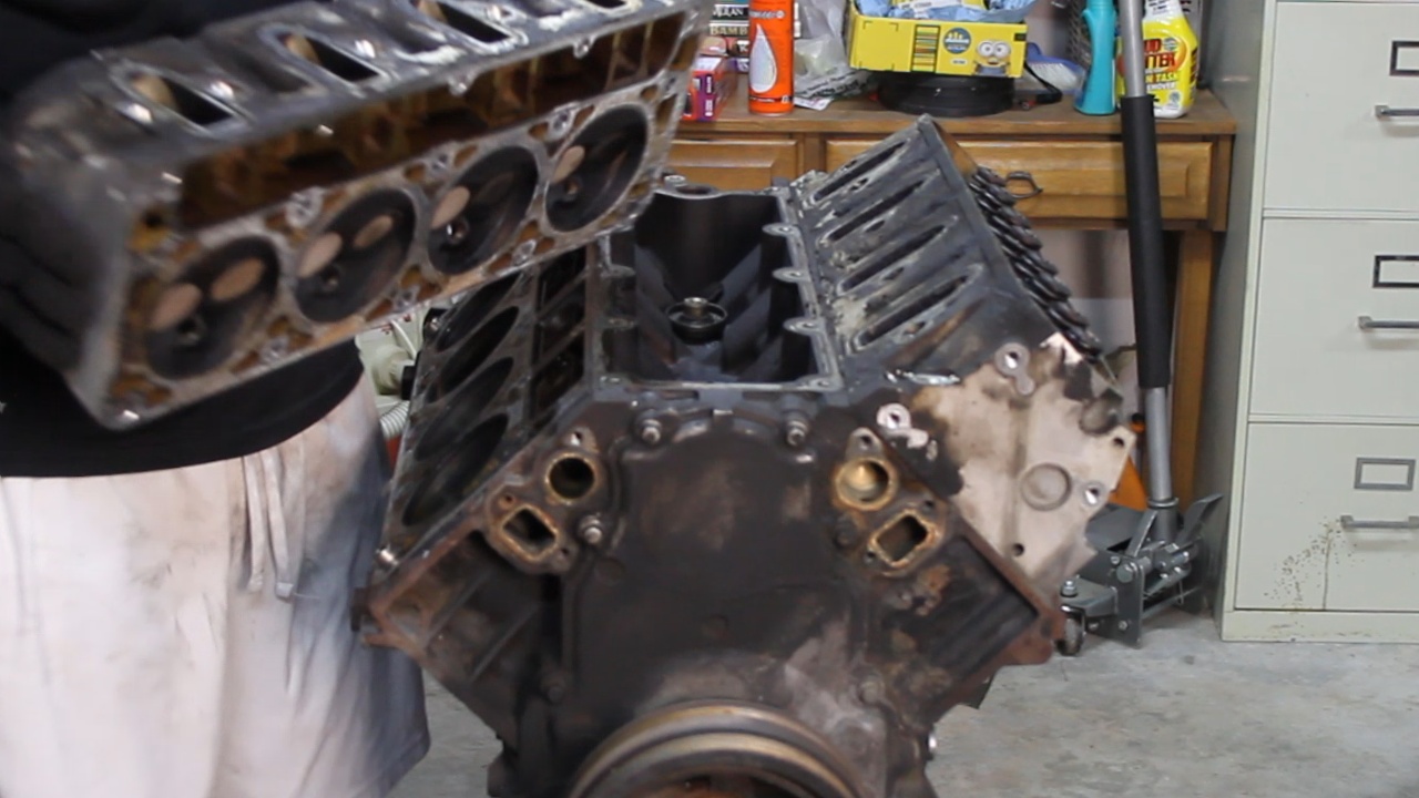
Pretty simple work so far. While many of these parts will not be used moving forward, I did keep them in order so that my machinist could do his proper inspection if needed. Next, we will be tearing down the Bottom End.
Next we removed the Knock Sensors and Valley Pan
Next was the removal of the Valve Covers which gave us the first look at the Valve Train and Cam
Next, we removed the Rocker Arms and Push Rods.
When removing the Exhaust Manifolds, we noticed that three of the bolts were broken off. I soaked what was left of the studs in Kroil overnight and was able to use vice grips to remove them.
Removed the 862 Heads and Lifters
Pretty simple work so far. While many of these parts will not be used moving forward, I did keep them in order so that my machinist could do his proper inspection if needed. Next, we will be tearing down the Bottom End.
Last edited by UcanDoIt2; May 8, 2017 at 10:34 PM.
Thread Starter
Teching In
Joined: May 2014
Posts: 39
Likes: 1
Here are some shots of the Bottom End Tear Down. And again while a lot of these parts will not be reused, I am keeping them in order just in case my machinist finds an issue and wants to cross reference parts to determine the extent or cause of the failure.
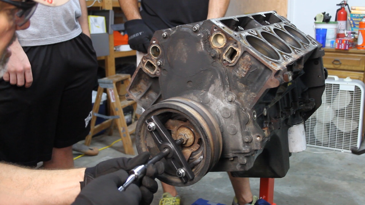
We then removed the Harmonic Balancer. The jaws of my HB puller were too thick and would not fit in the area required to perform the pull. I have to break out a bearing puller set to get this done.
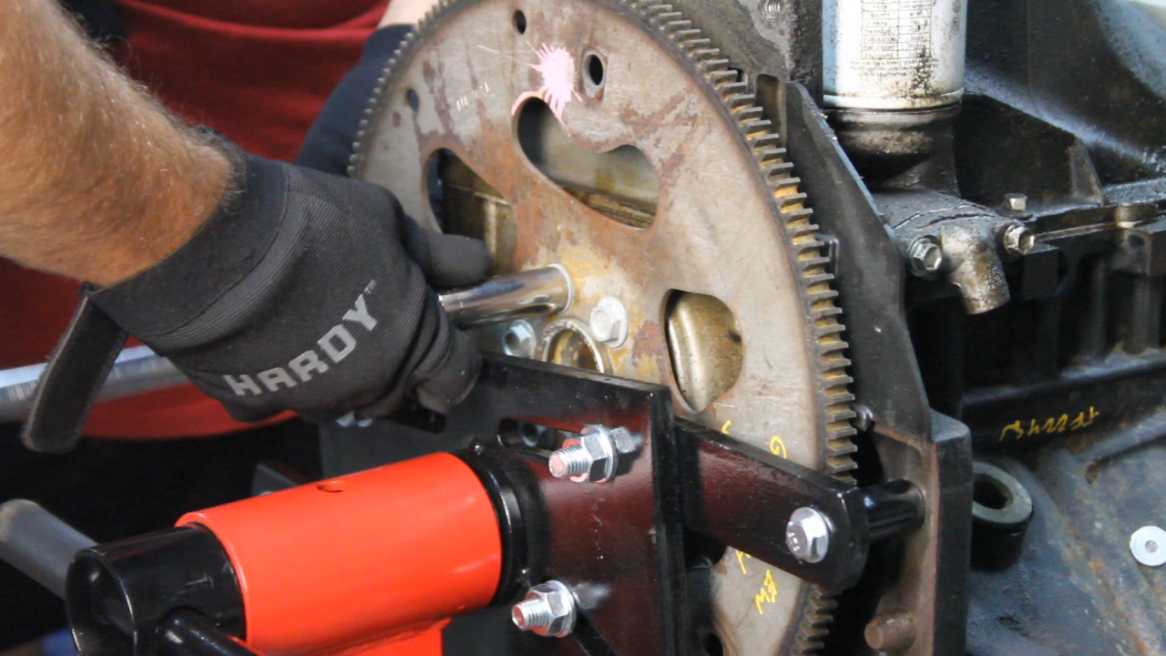
Then we removed the Flex Plate. Remember all 5.3L GM engines were only placed in front of Automatic transmissions. We will be replacing this Flex Plate with a Flywheel to support our AX15 5 Speed Transmission.
Next we remove the Oil Pan, Front Timing Cover and Rear Cover.
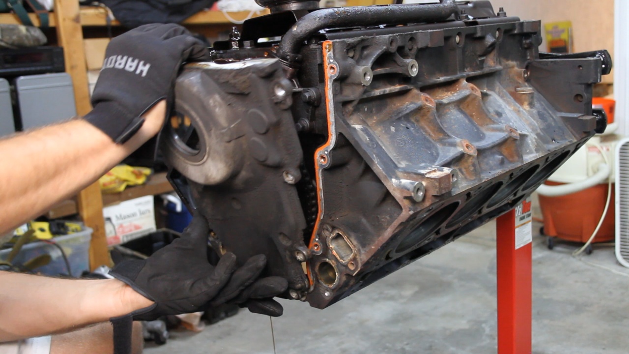
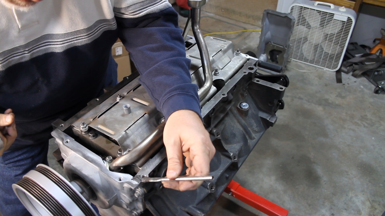
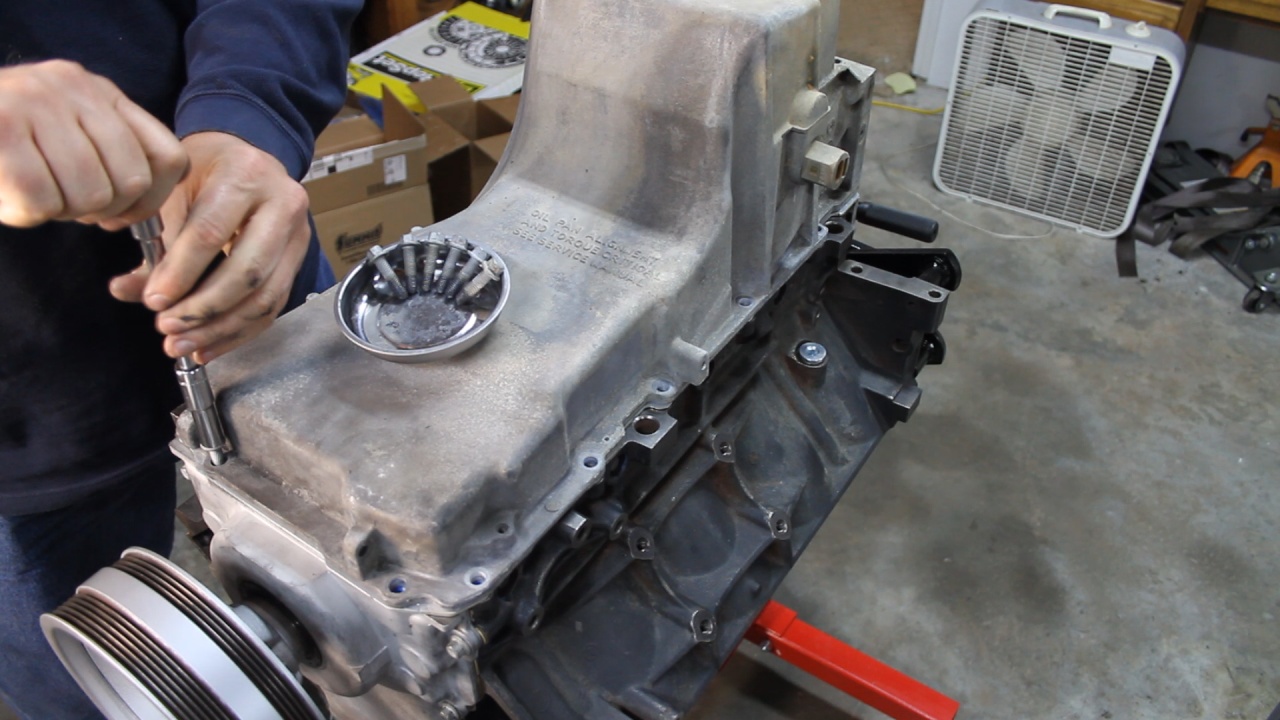
Then it was time to remove the Oil Pickup tube and Windage tray.
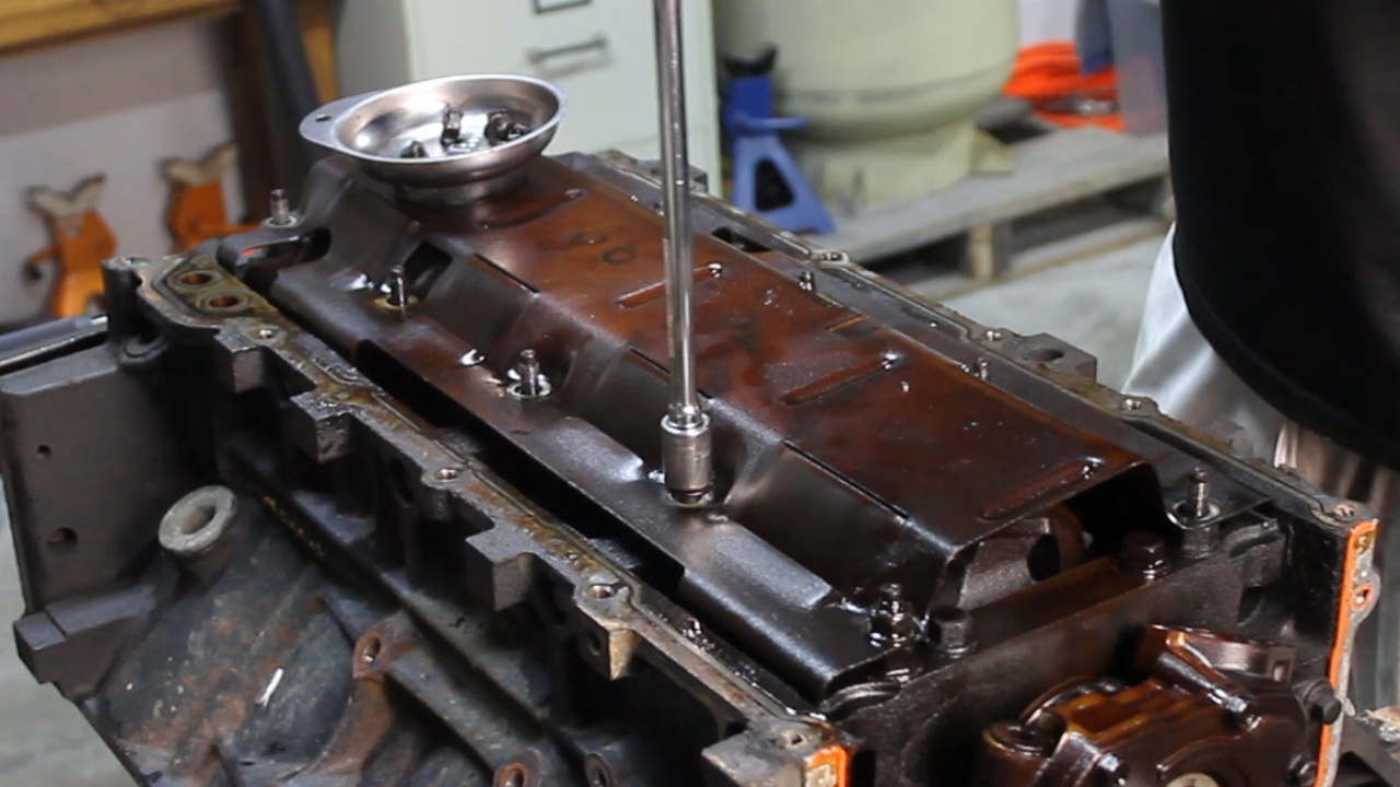
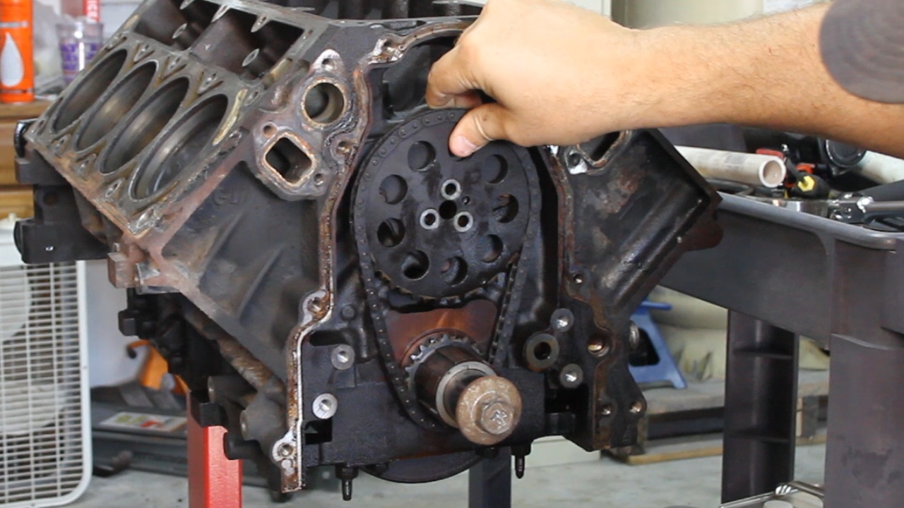
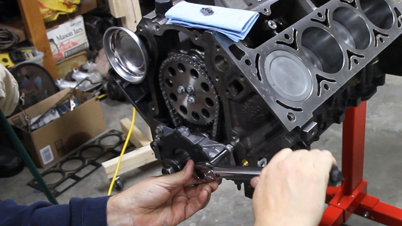
Then the Oil Pump and Timing Set
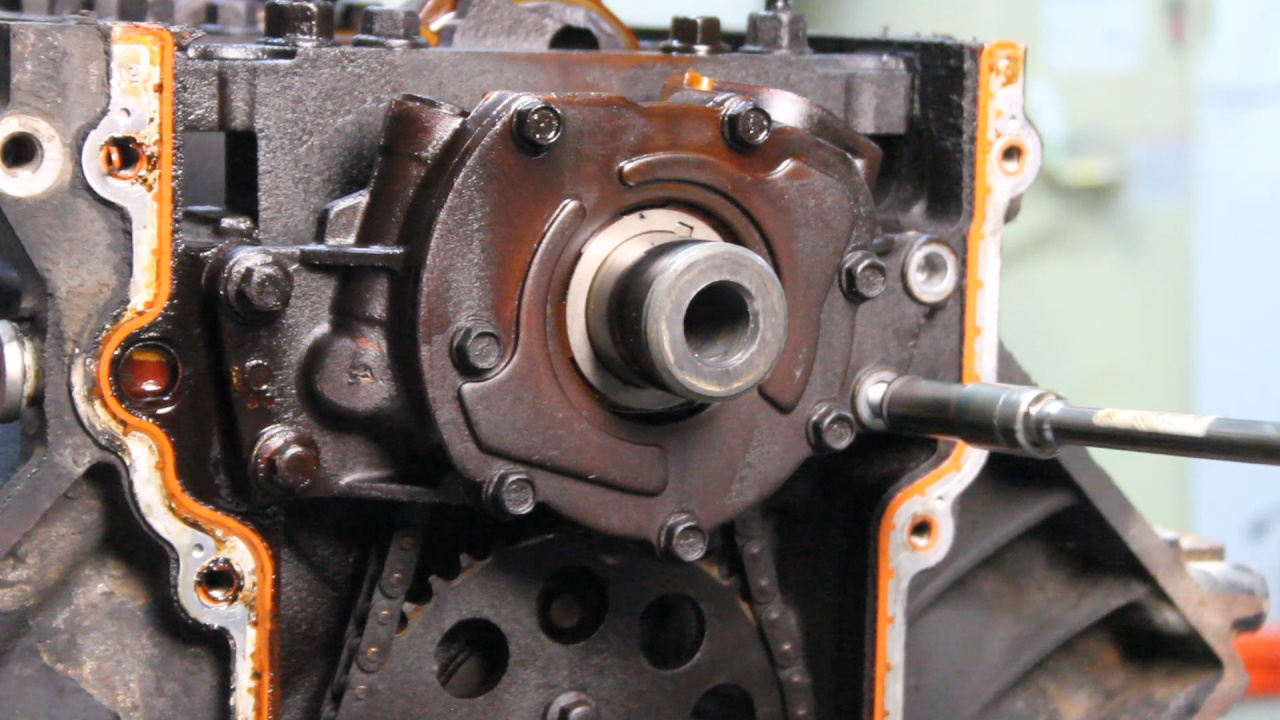
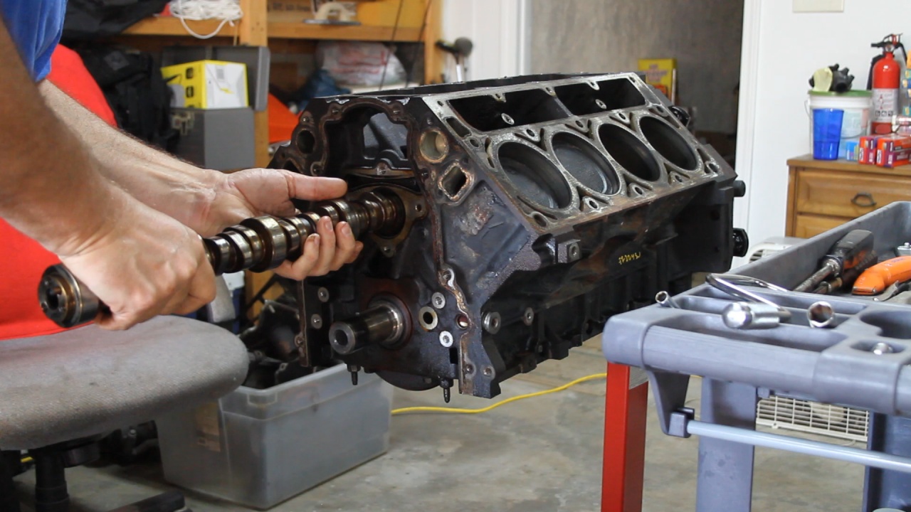
After removing the Cam Retainer, the Cam was pulled out.
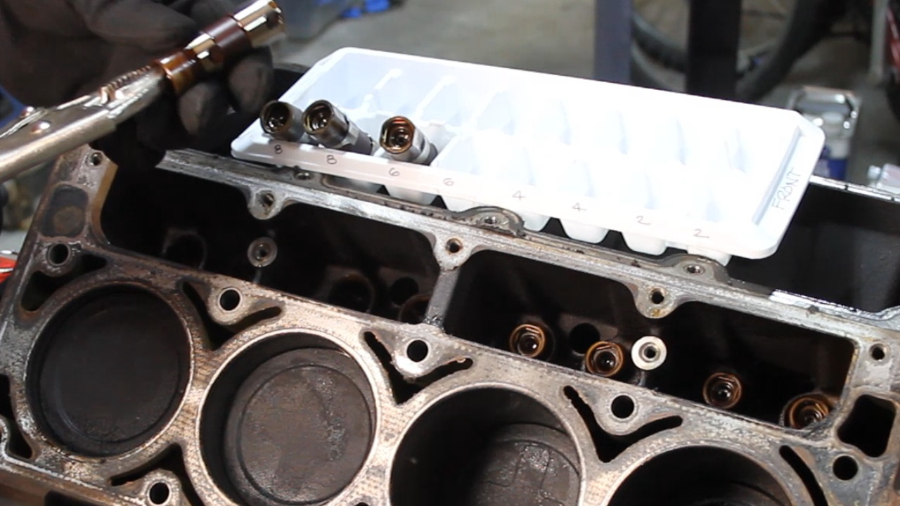
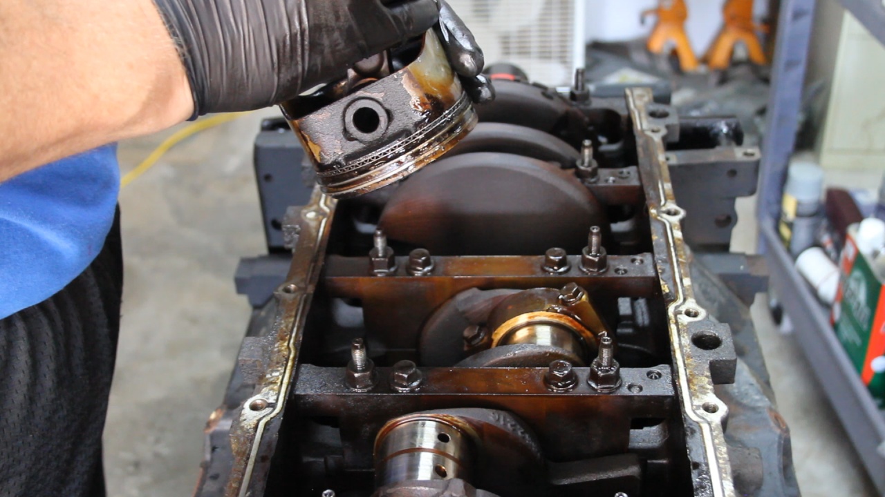
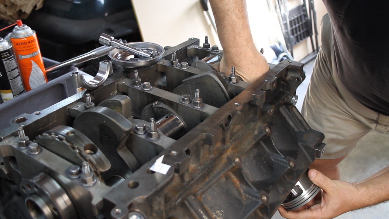
When taking out the Pistons, we made sure to keep them in order and replace the End Caps and bearings for future reference.
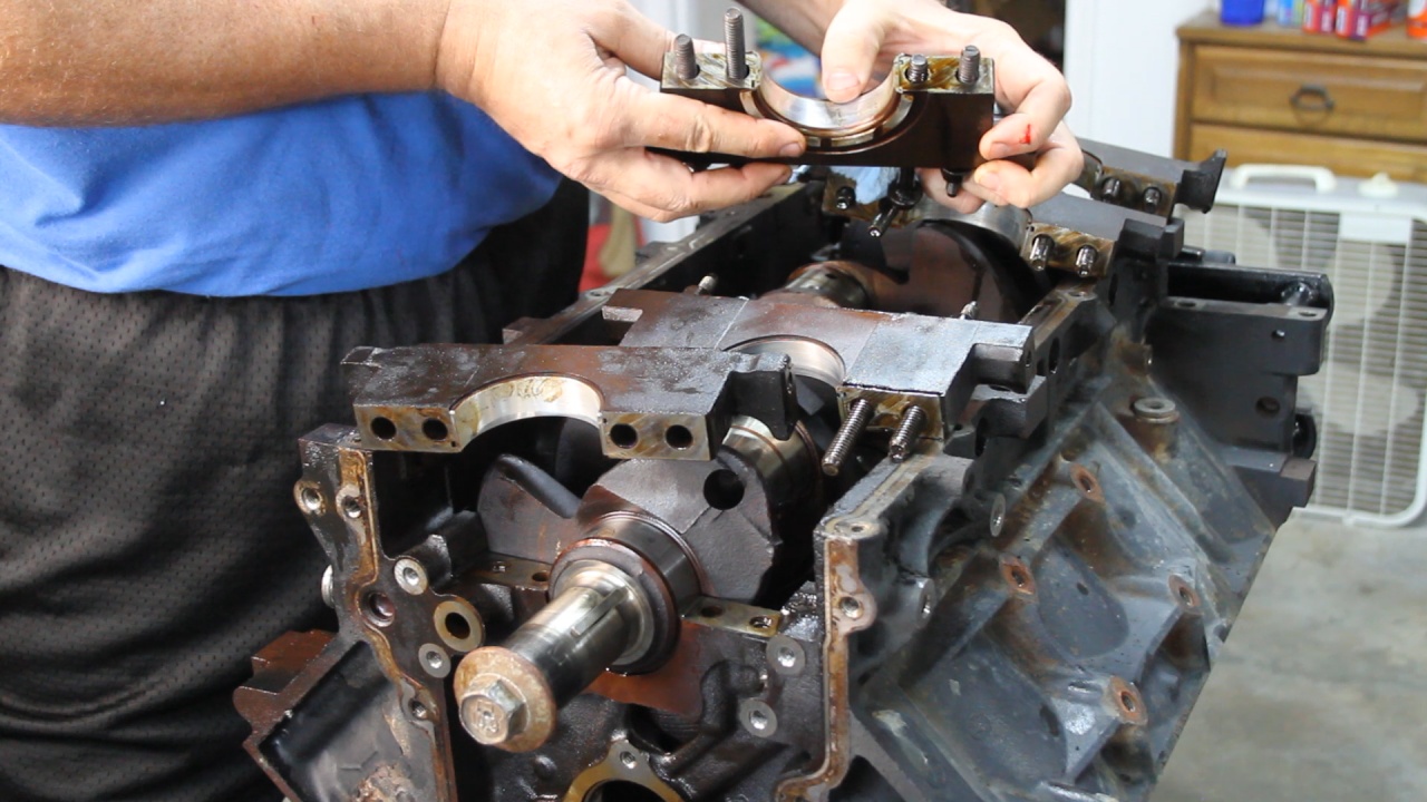
And finally, we removed all of the Main Bearing Caps just to check for spun bearings and check the condition. These were then put back so that the Crank could be delivered while still installed in the block to the machine shop.
We then removed the Harmonic Balancer. The jaws of my HB puller were too thick and would not fit in the area required to perform the pull. I have to break out a bearing puller set to get this done.
Then we removed the Flex Plate. Remember all 5.3L GM engines were only placed in front of Automatic transmissions. We will be replacing this Flex Plate with a Flywheel to support our AX15 5 Speed Transmission.
Next we remove the Oil Pan, Front Timing Cover and Rear Cover.
Then it was time to remove the Oil Pickup tube and Windage tray.
Then the Oil Pump and Timing Set
After removing the Cam Retainer, the Cam was pulled out.
When taking out the Pistons, we made sure to keep them in order and replace the End Caps and bearings for future reference.
And finally, we removed all of the Main Bearing Caps just to check for spun bearings and check the condition. These were then put back so that the Crank could be delivered while still installed in the block to the machine shop.
Last edited by UcanDoIt2; May 8, 2017 at 10:35 PM.
Trending Topics
Thread Starter
Teching In
Joined: May 2014
Posts: 39
Likes: 1
OK... This was a lot of fun. The machine shop allowed me to follow along with the machine work over the past couple of weeks. I will share a few of the photos here of several of the items that were done.
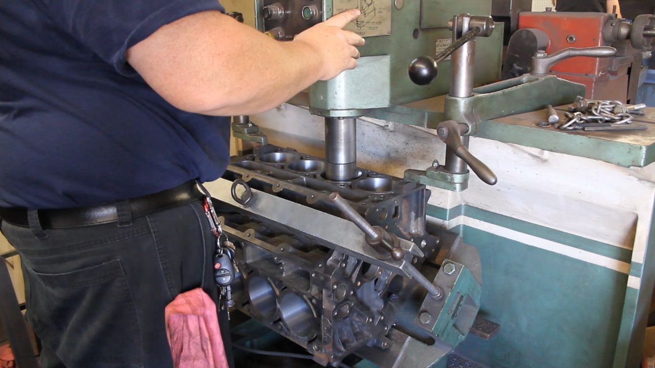
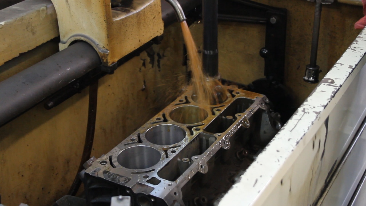
After fully cleaning all of the parts in either a Vat or Parts Washer, measurements were taken and an condition assessment was performed. With the block, it was determined that there was a slight taper and that taking 0.020 (20 thousandths) would allow us to correct the cylinders. Once we agreed on this, he ordered new Pistons. Here is a look at the first step of Boring the cylinders to remove the taper. This was done shy of the 0.020 increase as he would finalize the oversize during the Honing process.
Next we resurfaced the block surfaces making them extremely flat.
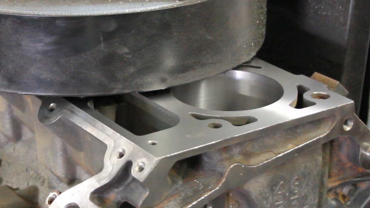
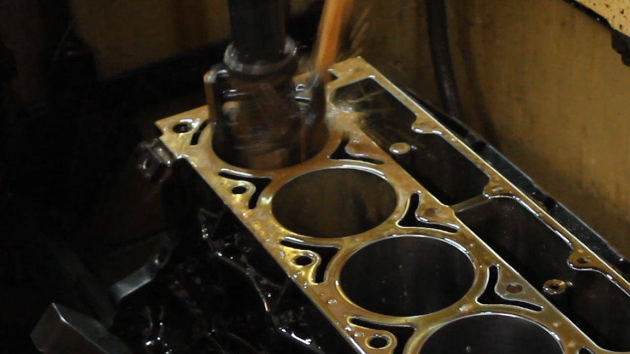
Then the block was installed in the Honing Machine and he make passes with 4 different grit honing stones through all 8 cylinders.
And then a final pass with some brushes that were intending to help remove all grit.
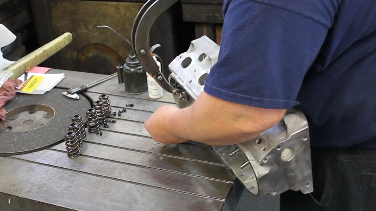
For the 862 Heads, he had taken some measurements of the original values. We ordered new valves and he dry fit them in the heads to determine the amount needed to grind off to make them the standard length. After that, he lubed and installed the new valves, valve seals, new Springs (for the Comp Cam), Retainers and Locks.
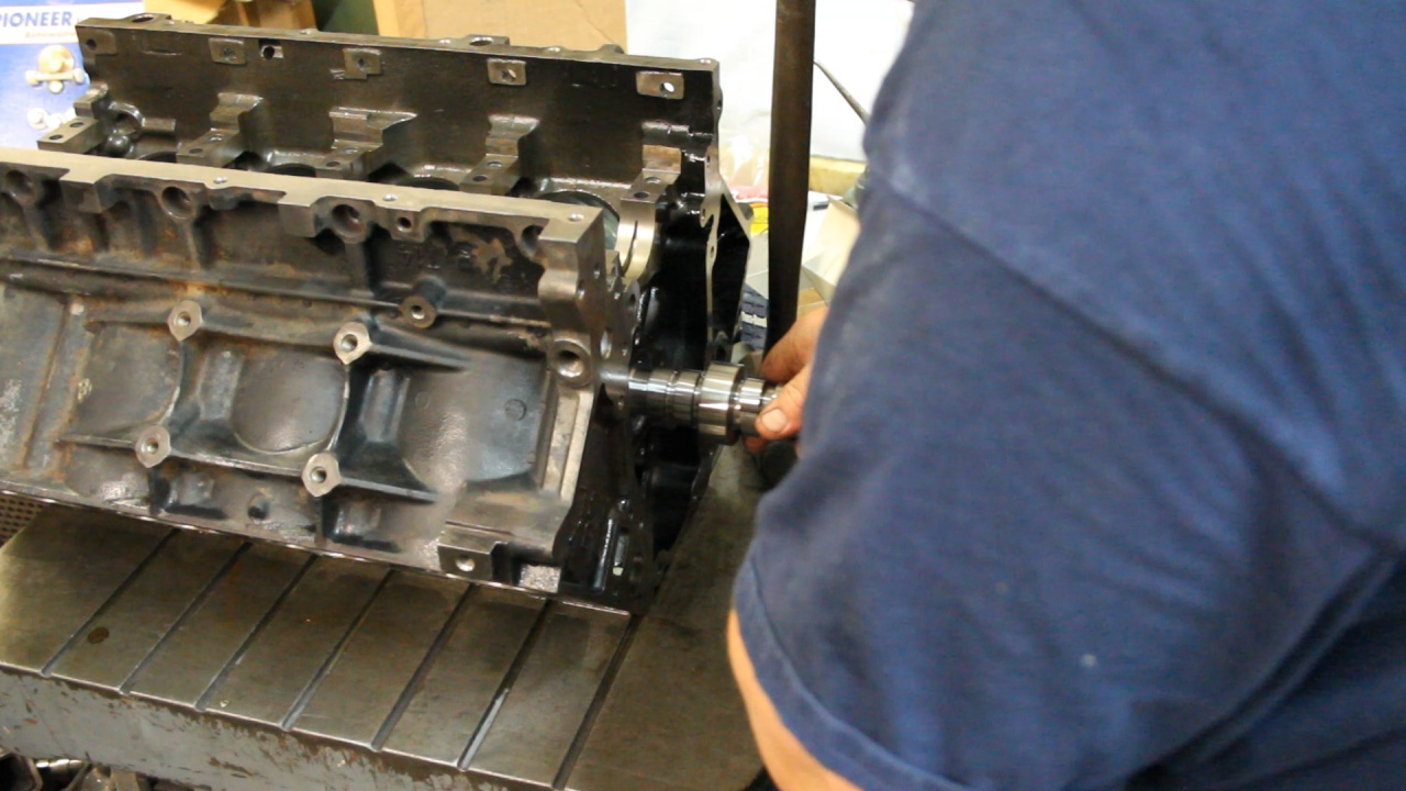
After installing new Camshaft Bearings, he installed the new Cam to verify that the bearing were properly aligned. Once verified, he lubed the Cam and we left it installed. No need to remove and reinstall.
Next he was to balance the Crankshaft rotating assembly. This involved establishing the weight of the new Pistons, Rods, Bearings, Rings, and an Oil allowance to create a temporary Bob Weight for the balancing process.
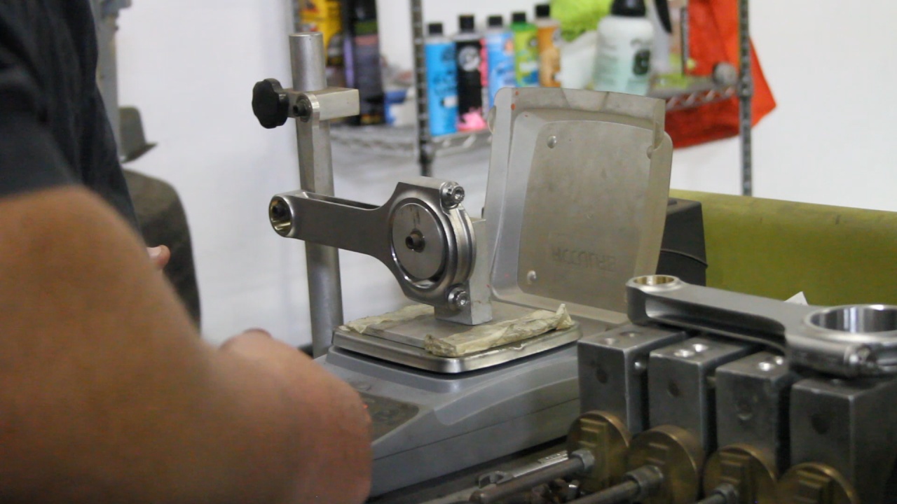
Here are the Bob Weights installed on the Crankshaft.
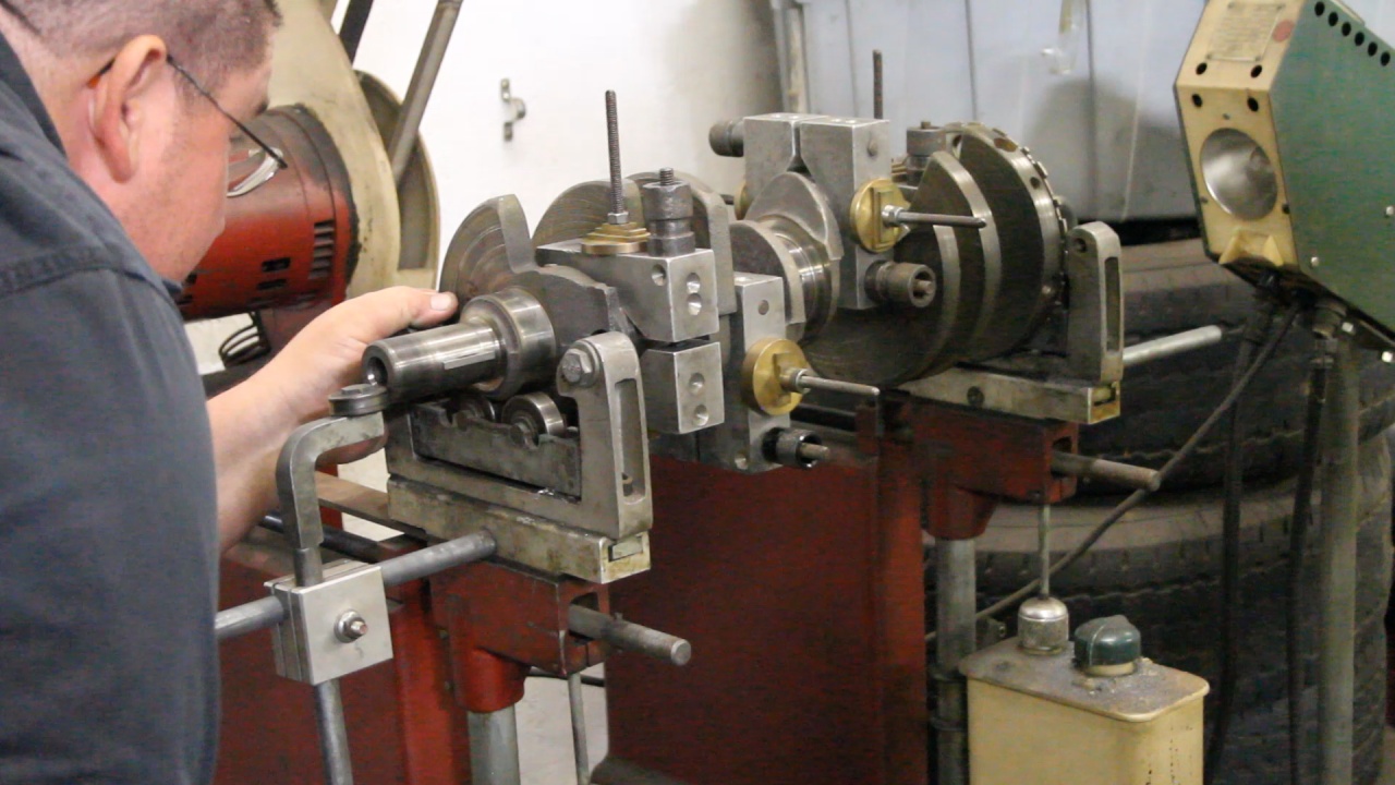
This crankshaft was initially balanced by itself, and then the Harmonic Balancer and New Flywheel were added. The New Flywheel was not balanced and after adjusting it's weight, the whole assembly was balanced.
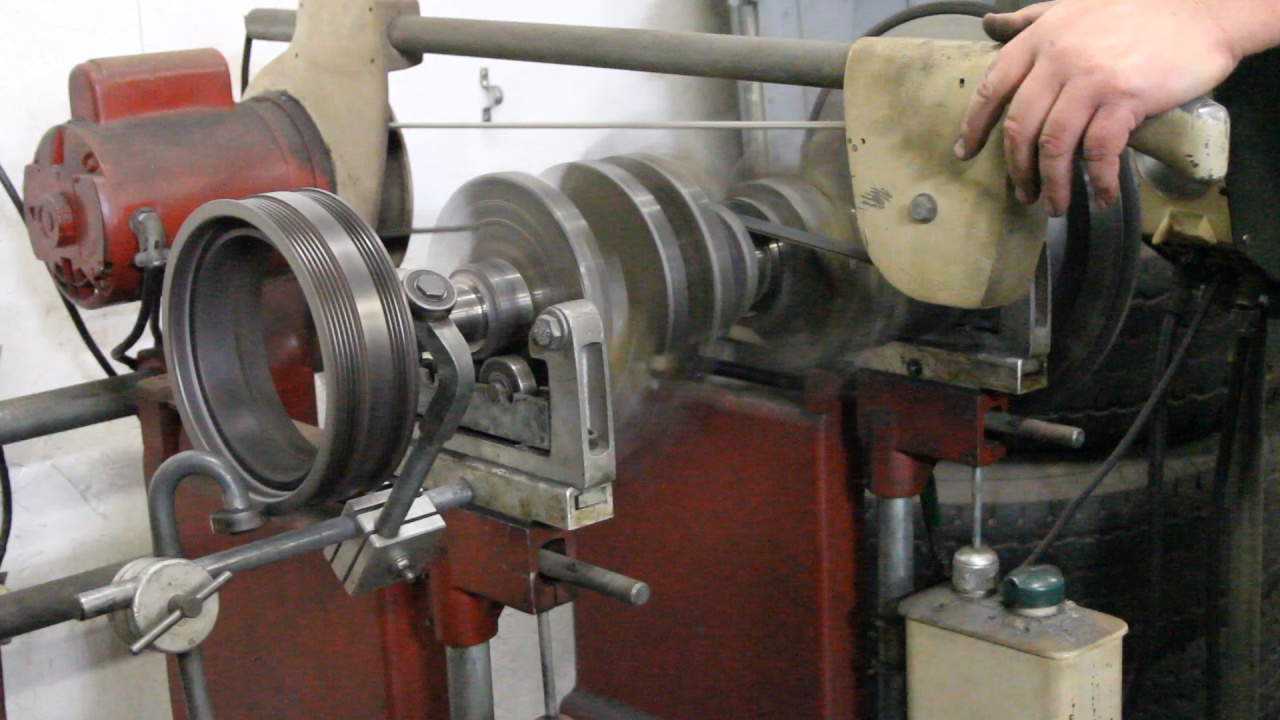
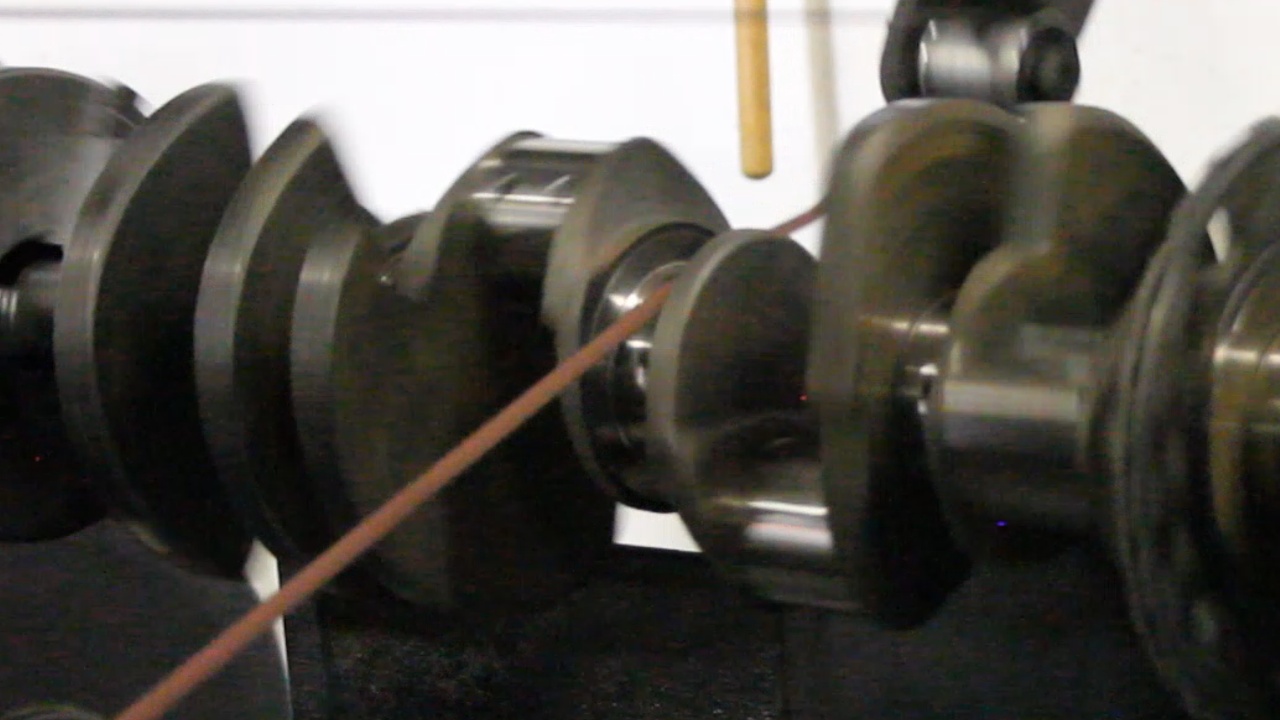
Now that it is balanced, journal measurements were taken and no adjustments were needed. Here he is polishing the Main and Rod journals.
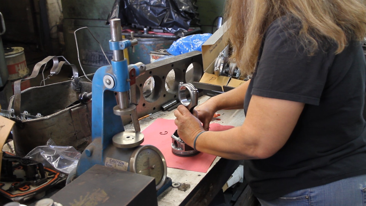
And finally, the Rods were attached to the Pistons. The rods are slightly offset, so 4 are installed one direction and the other 4 are install 180 degrees out.
These photos do give a great quick glance at what took place. I will also post a link to a video that covers these items in detail.
Overall, that was very educational and I relay enjoyed the several trips that I made to the shop. Hope you find this interesting.
After fully cleaning all of the parts in either a Vat or Parts Washer, measurements were taken and an condition assessment was performed. With the block, it was determined that there was a slight taper and that taking 0.020 (20 thousandths) would allow us to correct the cylinders. Once we agreed on this, he ordered new Pistons. Here is a look at the first step of Boring the cylinders to remove the taper. This was done shy of the 0.020 increase as he would finalize the oversize during the Honing process.
Next we resurfaced the block surfaces making them extremely flat.
Then the block was installed in the Honing Machine and he make passes with 4 different grit honing stones through all 8 cylinders.
And then a final pass with some brushes that were intending to help remove all grit.
For the 862 Heads, he had taken some measurements of the original values. We ordered new valves and he dry fit them in the heads to determine the amount needed to grind off to make them the standard length. After that, he lubed and installed the new valves, valve seals, new Springs (for the Comp Cam), Retainers and Locks.
After installing new Camshaft Bearings, he installed the new Cam to verify that the bearing were properly aligned. Once verified, he lubed the Cam and we left it installed. No need to remove and reinstall.
Next he was to balance the Crankshaft rotating assembly. This involved establishing the weight of the new Pistons, Rods, Bearings, Rings, and an Oil allowance to create a temporary Bob Weight for the balancing process.
Here are the Bob Weights installed on the Crankshaft.
This crankshaft was initially balanced by itself, and then the Harmonic Balancer and New Flywheel were added. The New Flywheel was not balanced and after adjusting it's weight, the whole assembly was balanced.
Now that it is balanced, journal measurements were taken and no adjustments were needed. Here he is polishing the Main and Rod journals.
And finally, the Rods were attached to the Pistons. The rods are slightly offset, so 4 are installed one direction and the other 4 are install 180 degrees out.
These photos do give a great quick glance at what took place. I will also post a link to a video that covers these items in detail.
Overall, that was very educational and I relay enjoyed the several trips that I made to the shop. Hope you find this interesting.
Last edited by UcanDoIt2; May 8, 2017 at 10:36 PM.
LS1 Tech Stories
The Best V8 Stories One Small Block at Time

Retro Modern Bandit Pontiac Trans AM Comes With Burt Reynolds' Autograph
Verdad Gallardo
Top 10 Greatest Cadillac V Series Performance Models Ever, Ranked
Pouria Savadkouei
Top 10 Most Powerful Chevy Trucks Ever Made!

Hennessey's New Supercharged Silverado ZR2 Has 700 HP
Verdad Gallardo
Coachbuilt N2A Anteros Is an LS2-Powered C6 Corvette In Italian Clothes
Verdad Gallardo
Awesome K5 Blazer Restomod Comes With C7 Corvette Power
Verdad Gallardo
10 Camaros You Should Never Buy

10 LS Engine Myths That Refuse to Die
Verdad Gallardo
Five Reasons the Camaro Was the Most Pivotal Player in the Pony Car Wars 2.0
Brett Foote Thread Starter
Teching In
Joined: May 2014
Posts: 39
Likes: 1
With all of the components back from the Machine Shop, it's time to get started assembling the bottom end. This took a little longer an I thought due to all of the clearance measurement that needs be taken. As we go along, we are cleaning and lubricating each section.
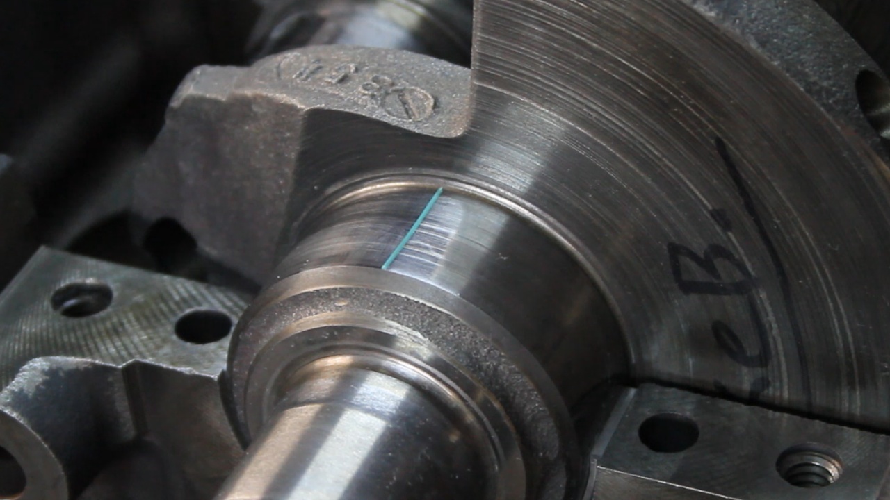
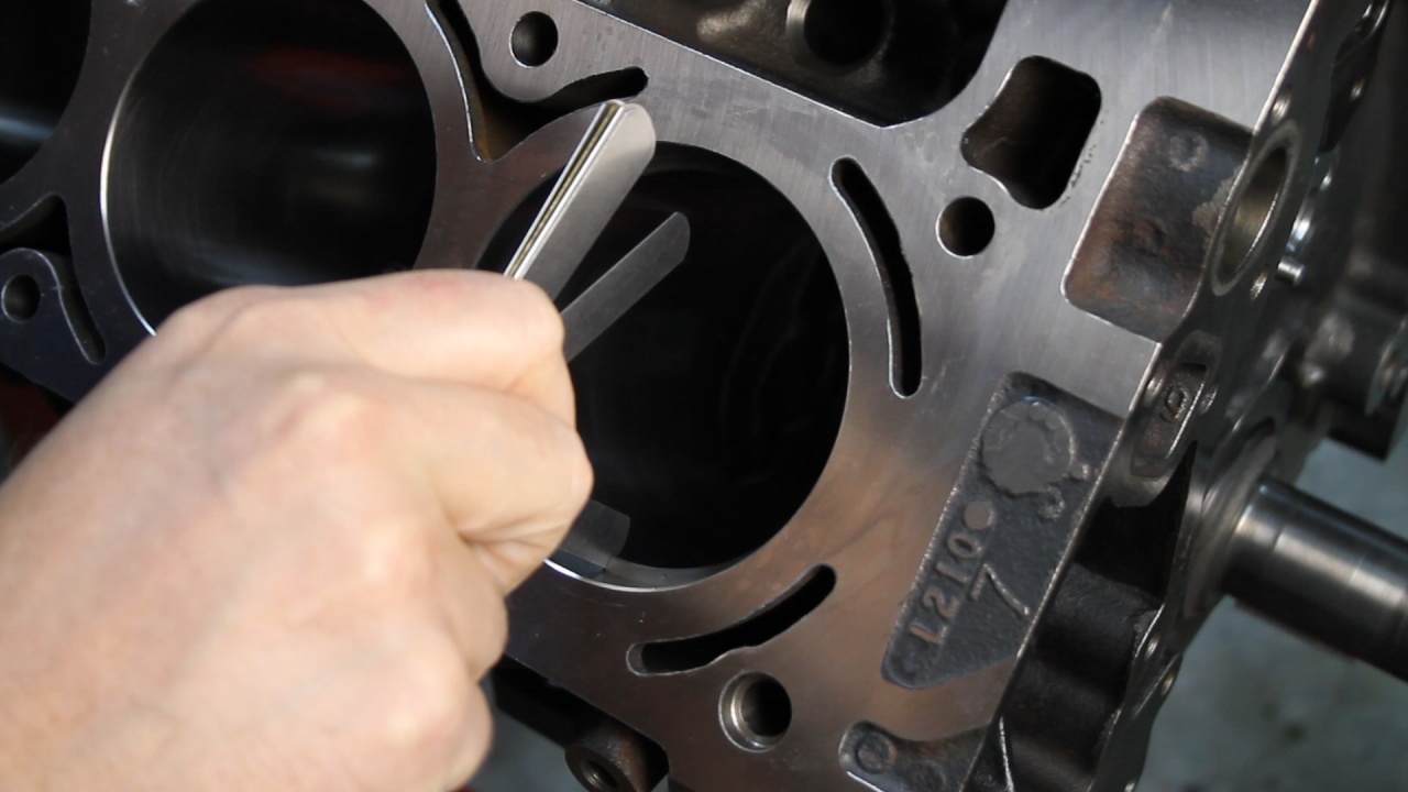
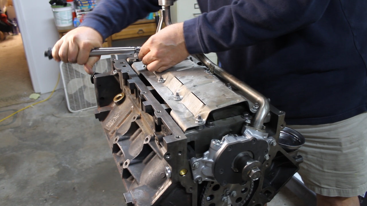
We started by checking the clearances on all 5 Main bearings. These are installed dry, and with the use of Plastigage, the clearance can be determined.
Here is the little strip of Plastigage
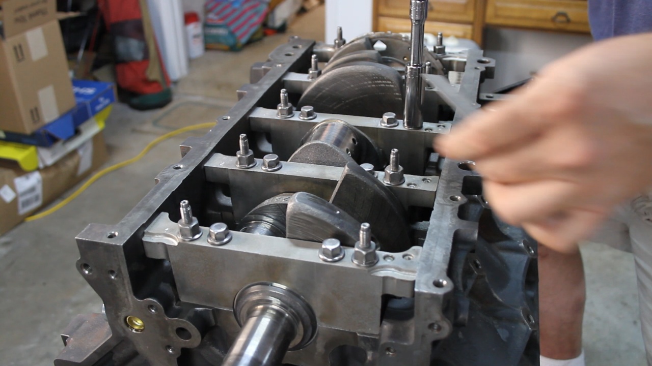
Here we are torqueing the Main Caps
Here is the Plastigage results. Each measured about 0.0018, which is very good.
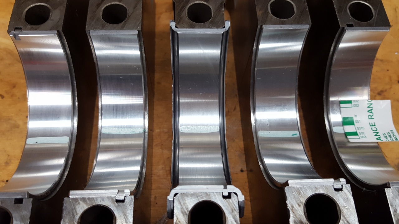
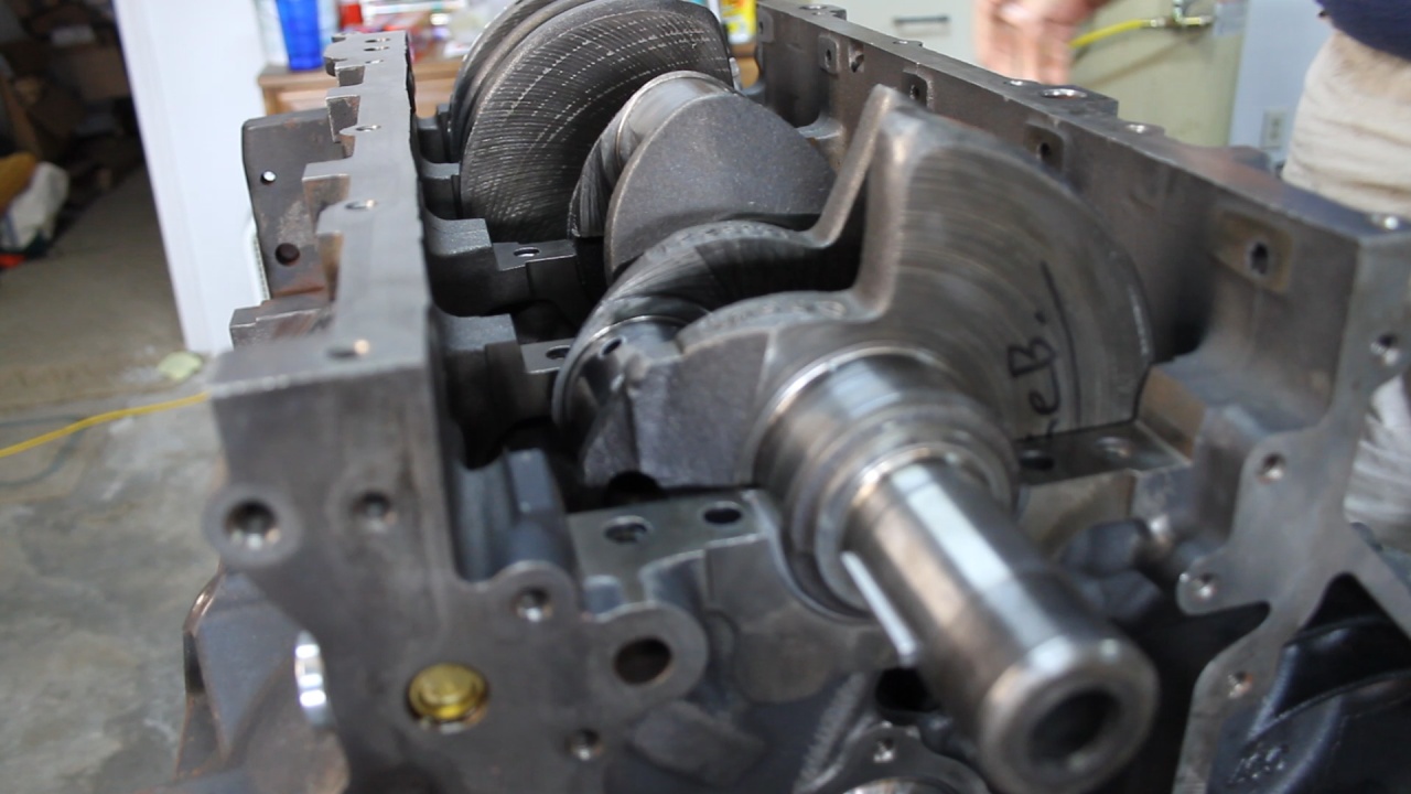
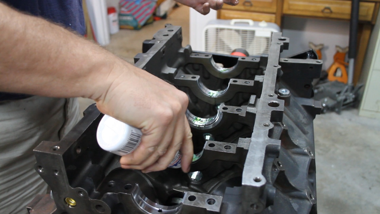
Now it was time to lube the Main Bearings and I also added assembly lube to the Camshaft lobes and then do a final install of the Crankshaft.
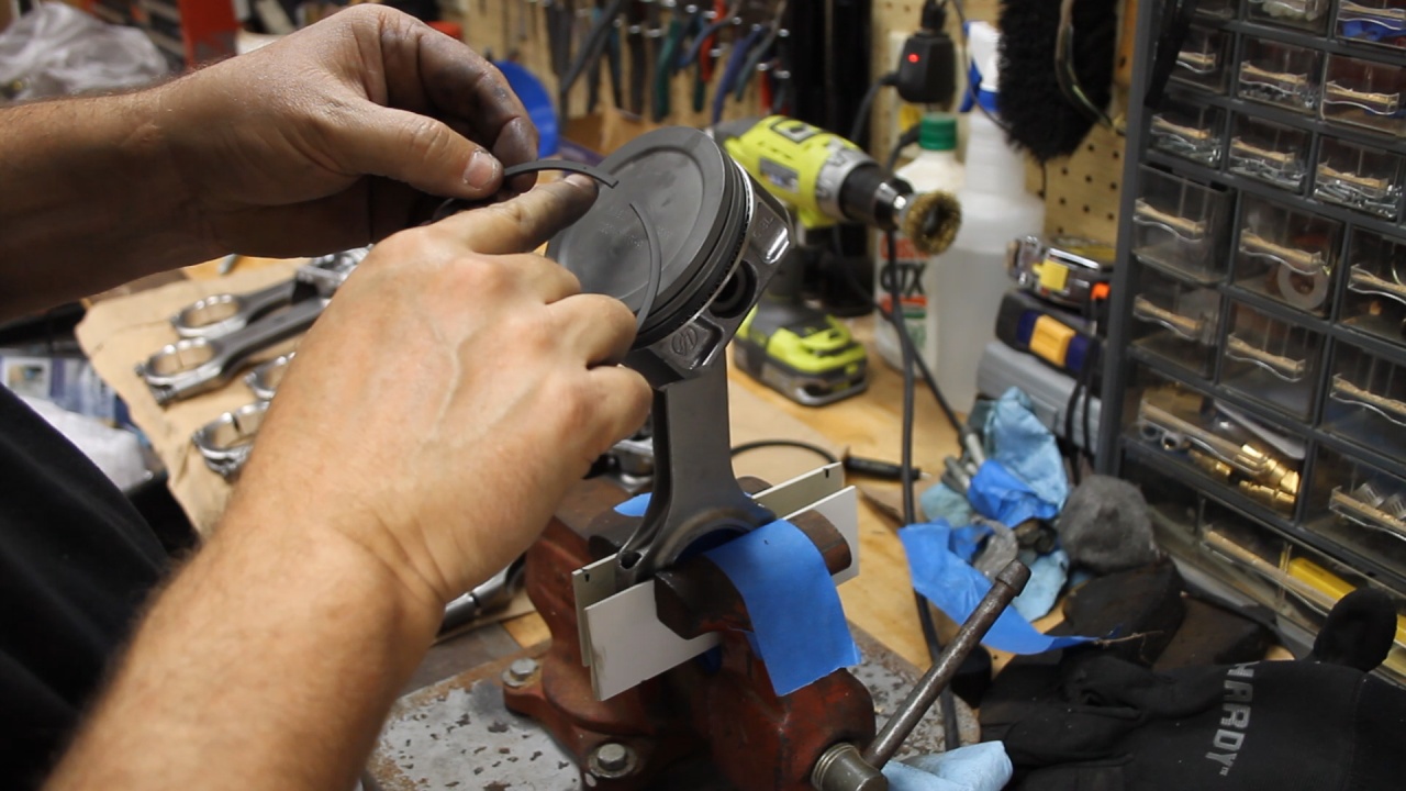
Next, I gapped the Rings and placed each set in groups assigned to each cylinder.
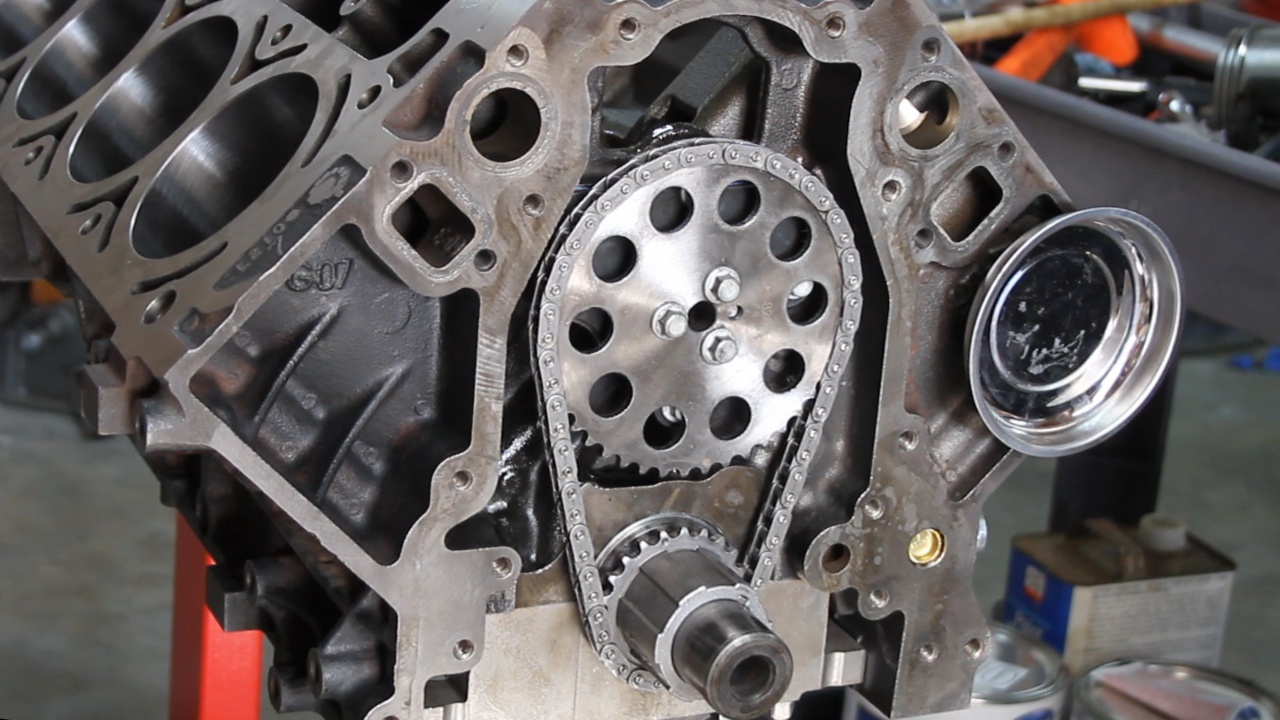
Then I installed the Timing Set
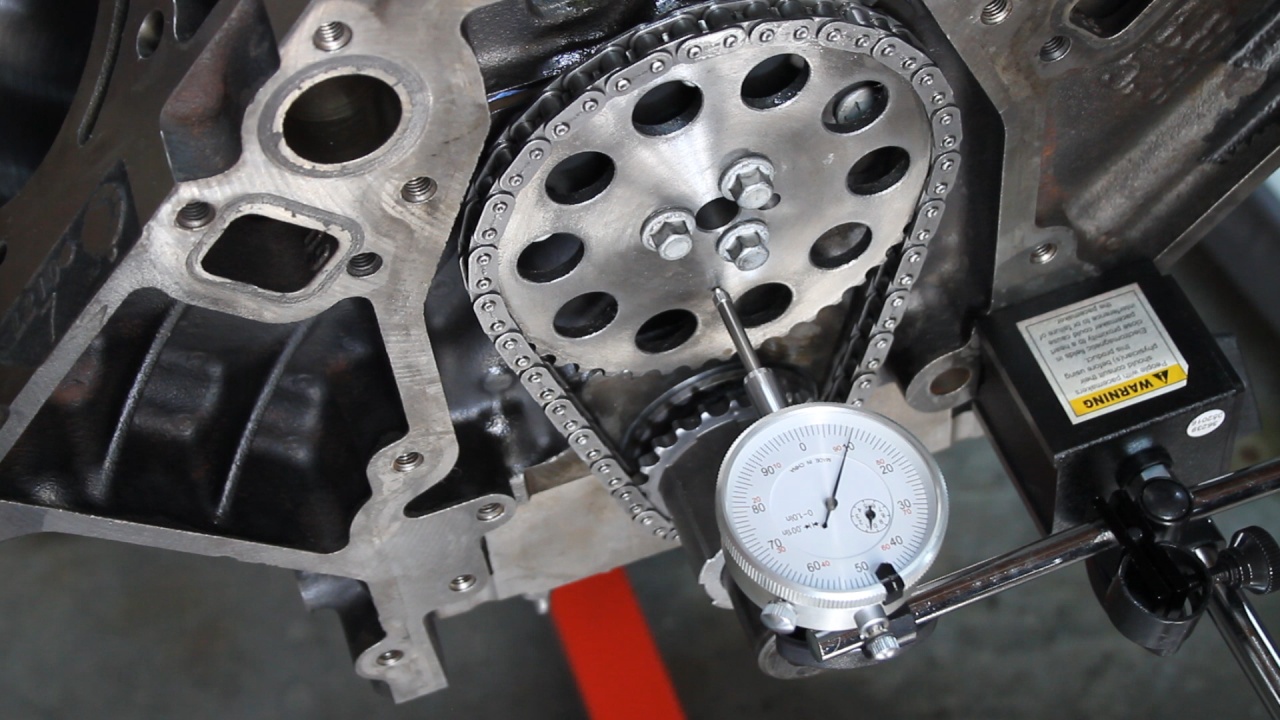
And measured the Camshaft end play.
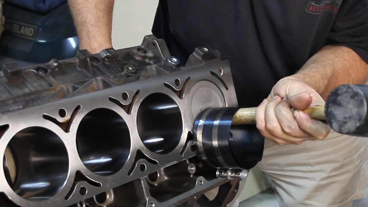
I then needed to measure the clearance on each of the Rod Bearing. I inserted the pistons without the rings and used plastigage to determine the rod clearance. They all were within spec near 0.0017.
Now it was time to install all the rings!:grin2:
To be honest, this took the better part of a lazy day. I took the opportunity to take my time and learn throughout the process. Spending the extra time here should really pay off.
We started by checking the clearances on all 5 Main bearings. These are installed dry, and with the use of Plastigage, the clearance can be determined.
Here is the little strip of Plastigage
Here we are torqueing the Main Caps
Here is the Plastigage results. Each measured about 0.0018, which is very good.
Now it was time to lube the Main Bearings and I also added assembly lube to the Camshaft lobes and then do a final install of the Crankshaft.
Next, I gapped the Rings and placed each set in groups assigned to each cylinder.
Then I installed the Timing Set
And measured the Camshaft end play.
I then needed to measure the clearance on each of the Rod Bearing. I inserted the pistons without the rings and used plastigage to determine the rod clearance. They all were within spec near 0.0017.
Now it was time to install all the rings!:grin2:
To be honest, this took the better part of a lazy day. I took the opportunity to take my time and learn throughout the process. Spending the extra time here should really pay off.
Last edited by UcanDoIt2; May 8, 2017 at 10:37 PM.
Thread Starter
Teching In
Joined: May 2014
Posts: 39
Likes: 1
Well I have a few updates. Worked on getting the Oil Pump and all the lower end covers installed. I was delayed for several days due to purchasing a bolt I needed to install the Harmonic Balancer.
Started with Melling Oil Pump model M295. This is Melling's Standard model which does provide slightly higher oil flow than the EOM unit. This should pump should provide excellent oil pressure for all the new parts. This unit has a sacrificial ring built-in that helps you center the unit's placement.
Next, I installed the Windage Tray and Oil Pickup Tube.
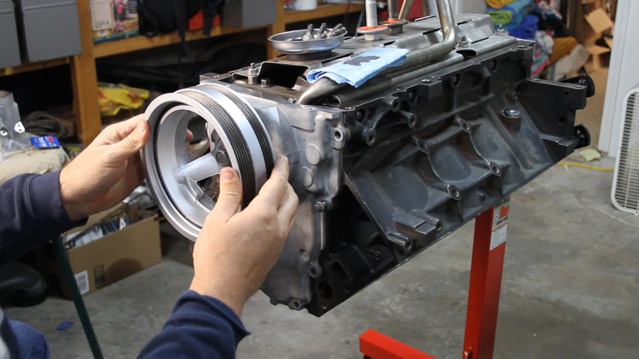
To install the front Timing Cover, I partially installed the Harmonic Balancer so that the large hole in the cover could self-center itself. Then I used a straight edge to make sure that both lower surfaces are flush with the lower block surface.
Used the same logic on installing the Rear Cover. This was pretty straight forward and eliminated the need to purchase the "Special Alignment Tool". All-in-All I am very confident that both covers are in good alignment and should not leak.
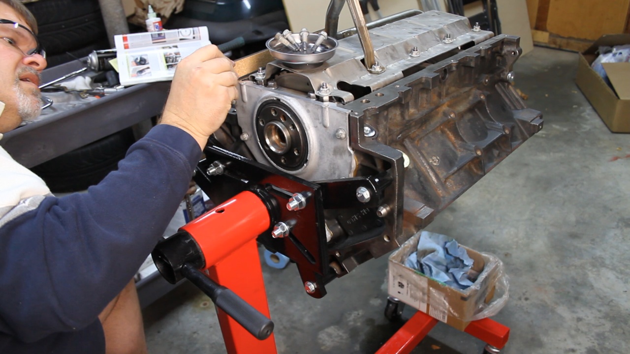
Added a little gasket sealer to the four corners where the covers touch the block.
Wrapped it up with the installation of the Oil Pan. For now, it is my understanding that this Oil Pan will work in my CJ7 swap. We will learn more about that when we check it for fitment.
Started with Melling Oil Pump model M295. This is Melling's Standard model which does provide slightly higher oil flow than the EOM unit. This should pump should provide excellent oil pressure for all the new parts. This unit has a sacrificial ring built-in that helps you center the unit's placement.
Next, I installed the Windage Tray and Oil Pickup Tube.
To install the front Timing Cover, I partially installed the Harmonic Balancer so that the large hole in the cover could self-center itself. Then I used a straight edge to make sure that both lower surfaces are flush with the lower block surface.
Used the same logic on installing the Rear Cover. This was pretty straight forward and eliminated the need to purchase the "Special Alignment Tool". All-in-All I am very confident that both covers are in good alignment and should not leak.
Added a little gasket sealer to the four corners where the covers touch the block.
Wrapped it up with the installation of the Oil Pan. For now, it is my understanding that this Oil Pan will work in my CJ7 swap. We will learn more about that when we check it for fitment.
Last edited by UcanDoIt2; May 8, 2017 at 10:39 PM.
Thread Starter
Teching In
Joined: May 2014
Posts: 39
Likes: 1
Started the final assembly steps that will take place prior to hitting it with paint. Here is what we have recently accomplished.
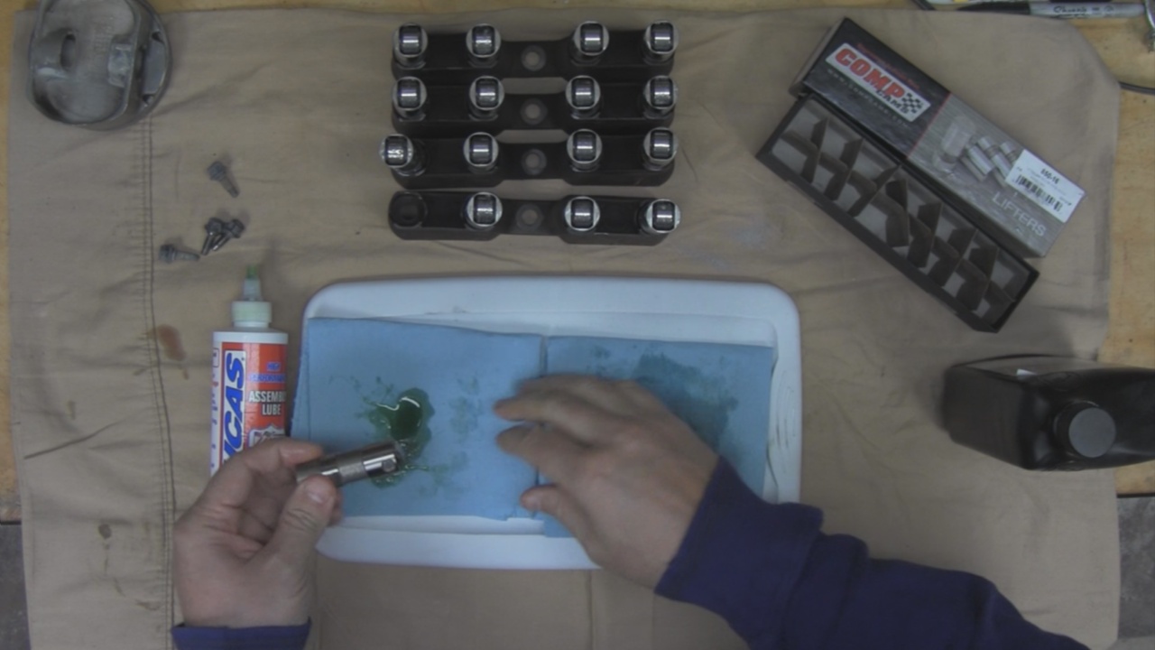
Lubricated the Hydraulic Lifters. I remember in previous builds having to soak the Lifters in oil so that they would fill up. My Machinist had mentioned not to do this. I was looking through the Manual and the Instructions that came from Comp Cams and they all agreed not to presoak the lifters. I did want to lubricate then though, so here I am applying some of the W30 break-in oil to the outer surface. I also applied Engine Assembly Lube on the roller.
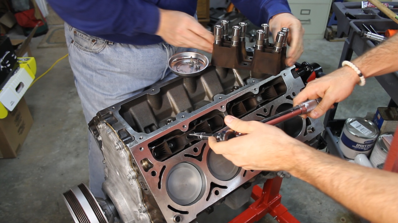
After installing the Lifters into the Lifter Trays, those were installed in place and bolted down.
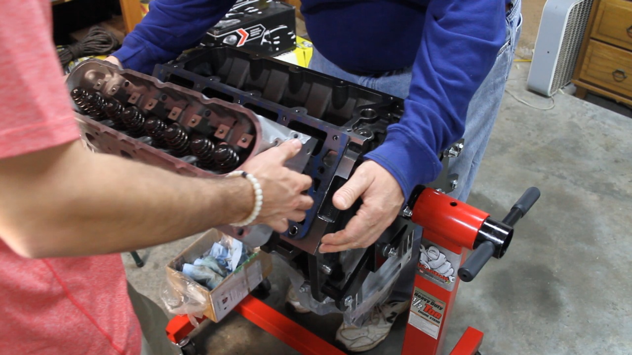
Next it was time to add the Head Gasket and 862 Aluminum Heads. These FelPRO Gaskets are clearly marked Front, but they do not care which side is up. Good thing, because the only way to install them is to have one Blue side up and one of then Blue side down.
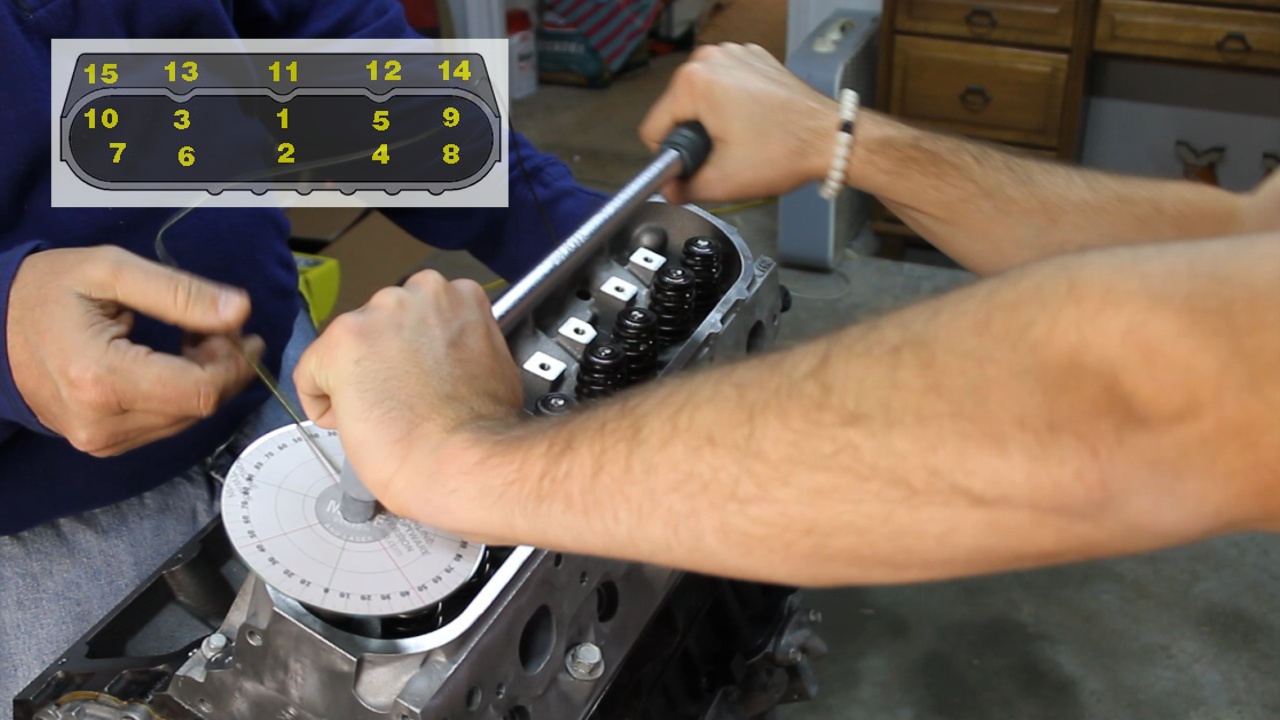
We are using new Head Bolts as these are the Torque to Yield style and it is very clear everywhere you read, not to reuse the old ones. It takes 3 passes following the Torque sequence to install these. The last two passes is based on Angle and not torque. I created my own Torque Angle Gauge using an old CD, CD Label, and a Degree image found on the internet. With a slight adjustment to the inside diameter of the CD hole, I was able to get a snug fit on the ratchet extension and this seemed to work perfectly.
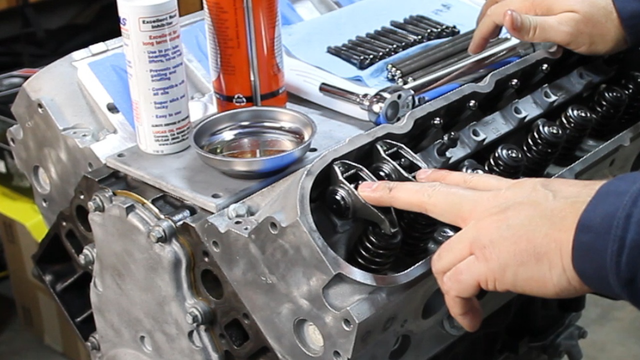
The next step was to install the new Rocker Arms. These are the standard 1.7 ration replacements. This step involved rotating the crank until the Exhaust pushrod just began to lift. This placed the Intake side on the Cam's base circle where there is no lift and was the correct position to install that cylinder's Intake Rocker. After the Intake Rocket was installed, we rotated the crank until the Intake Valved opened and then closed and just before it finished closing, was the correct position to install the Exhaust Rocker Arm.
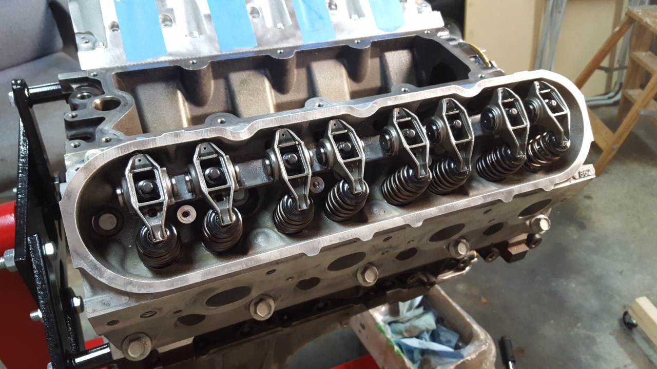
We did that procedure for all 8 cylinders and ended up with this.
I believe I am going to tape up portions of this assembly and remaining parts and begin doing some painting. That will be the next steps.
Lubricated the Hydraulic Lifters. I remember in previous builds having to soak the Lifters in oil so that they would fill up. My Machinist had mentioned not to do this. I was looking through the Manual and the Instructions that came from Comp Cams and they all agreed not to presoak the lifters. I did want to lubricate then though, so here I am applying some of the W30 break-in oil to the outer surface. I also applied Engine Assembly Lube on the roller.
After installing the Lifters into the Lifter Trays, those were installed in place and bolted down.
Next it was time to add the Head Gasket and 862 Aluminum Heads. These FelPRO Gaskets are clearly marked Front, but they do not care which side is up. Good thing, because the only way to install them is to have one Blue side up and one of then Blue side down.
We are using new Head Bolts as these are the Torque to Yield style and it is very clear everywhere you read, not to reuse the old ones. It takes 3 passes following the Torque sequence to install these. The last two passes is based on Angle and not torque. I created my own Torque Angle Gauge using an old CD, CD Label, and a Degree image found on the internet. With a slight adjustment to the inside diameter of the CD hole, I was able to get a snug fit on the ratchet extension and this seemed to work perfectly.
The next step was to install the new Rocker Arms. These are the standard 1.7 ration replacements. This step involved rotating the crank until the Exhaust pushrod just began to lift. This placed the Intake side on the Cam's base circle where there is no lift and was the correct position to install that cylinder's Intake Rocker. After the Intake Rocket was installed, we rotated the crank until the Intake Valved opened and then closed and just before it finished closing, was the correct position to install the Exhaust Rocker Arm.
We did that procedure for all 8 cylinders and ended up with this.
I believe I am going to tape up portions of this assembly and remaining parts and begin doing some painting. That will be the next steps.
Last edited by UcanDoIt2; May 8, 2017 at 10:40 PM.
Thread Starter
Teching In
Joined: May 2014
Posts: 39
Likes: 1
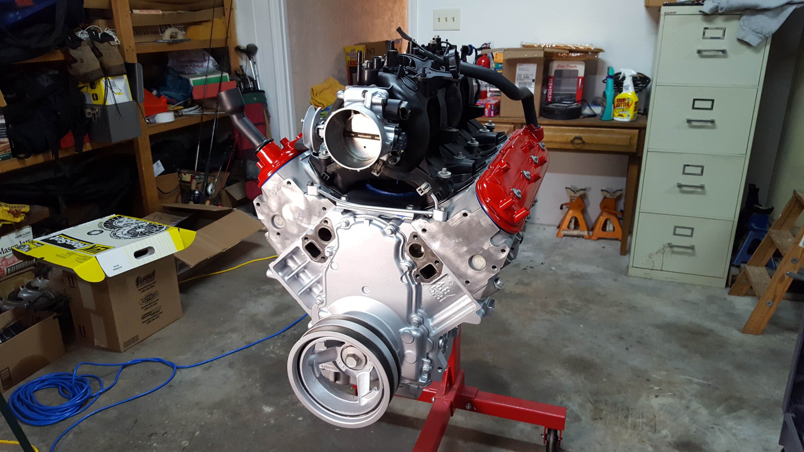
It's starting to look like an engine!!!!
Took some time to do some careful masking and then took the Paint to it! In this photo, I am applying the 3rd coat of paint to the main assembly. I decided to mask off the Heads and leave them unpainted to show off the natural aluminum finish.
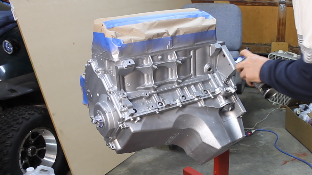
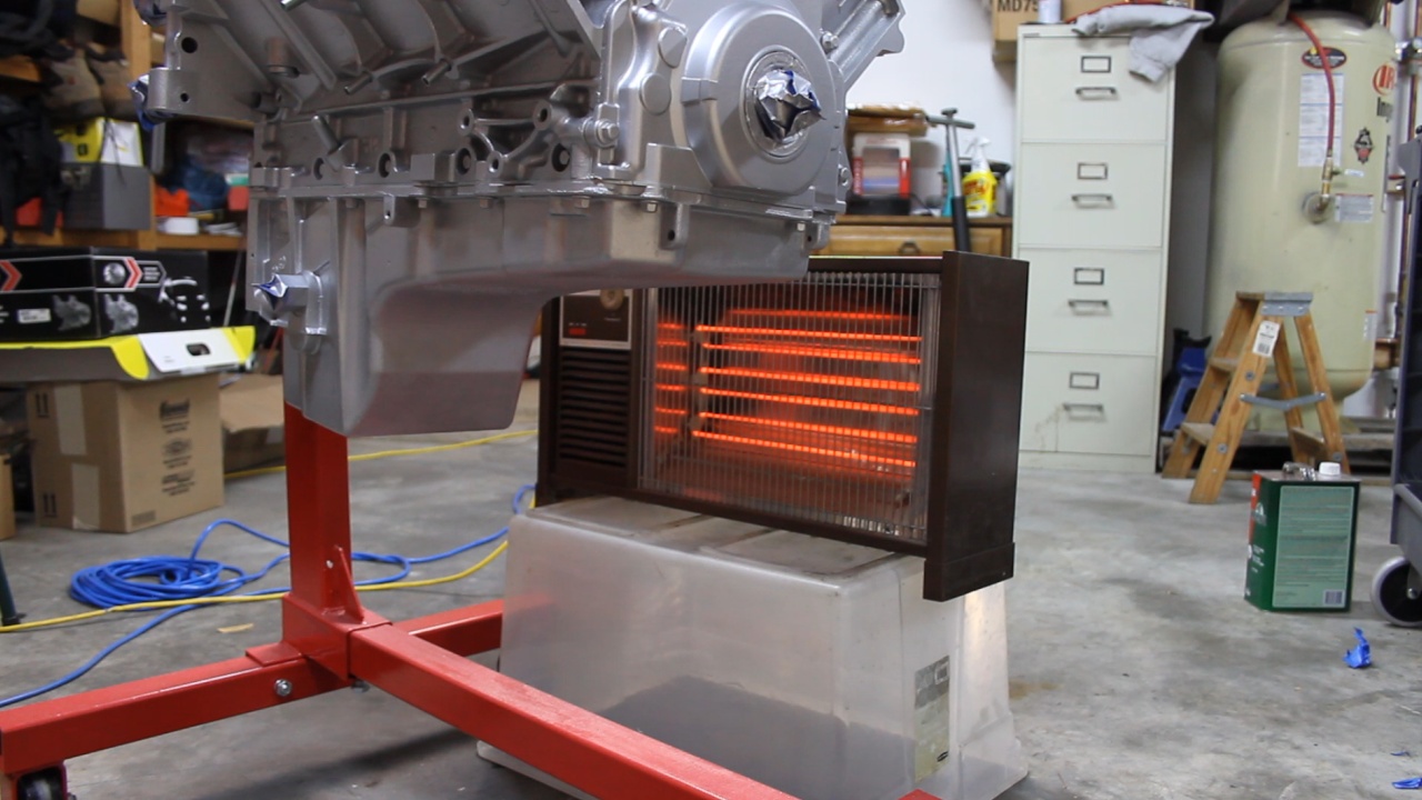
After painting with VHT high temp paint, I used a small electric heater to help partially bake it on. Over several hours, I moved the heater to help bake different areas of the assembly.
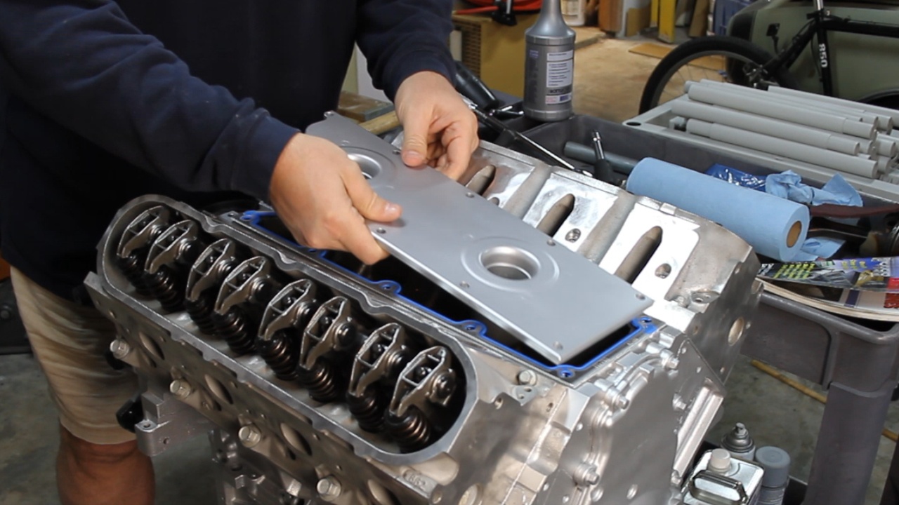
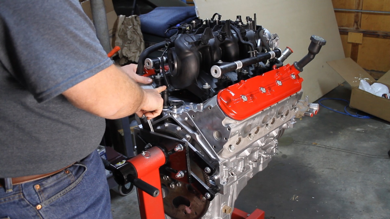
Next, the Valley Pan cover and Knock Sensors were installed.
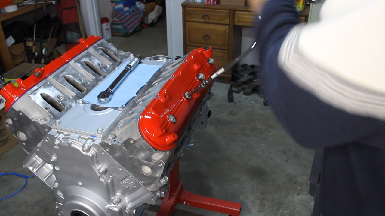
Are you ready? Here I am installing the Vavle covers. These were painted separately and baked in the oven. Wasn't sure if I was going to like this, but after installing them, I think it turned out really good. The Jeep is going to be Red and I thought this small touch, would help tie it all together.
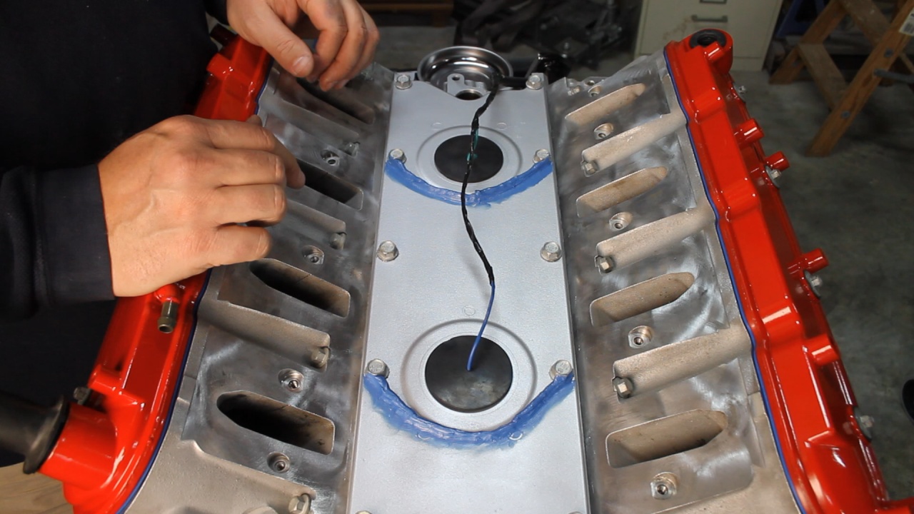
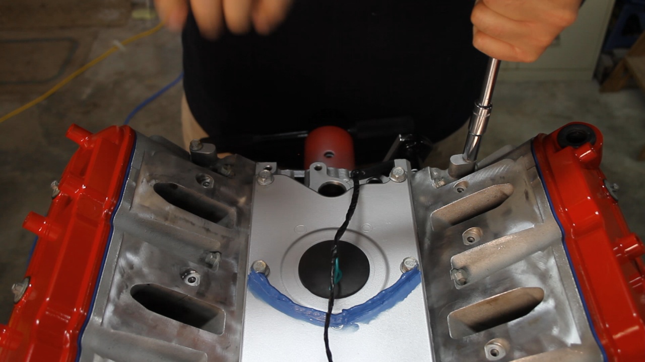
After installing the new Knock Sensor wiring harness, I followed the GM TSB and added a small silicone dam to help divert water around the sensor locations. Water does not play nicely with the sensors.
Next, it was time for the Coolant Vent Block offs in the rear and Tube in the front.
After putting on the new FelPRO Intake Gaskets, I installed and torqued down the Intake
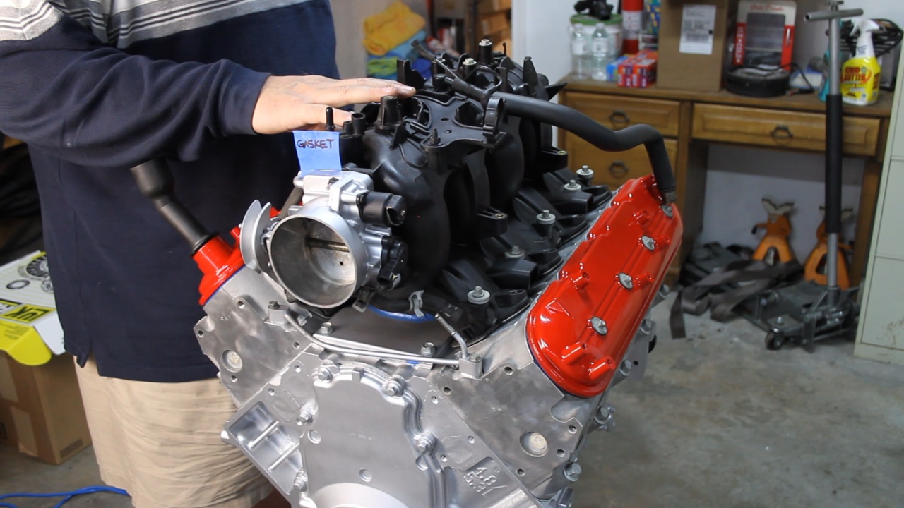
Here the new Throttle Body Gasket gets installed

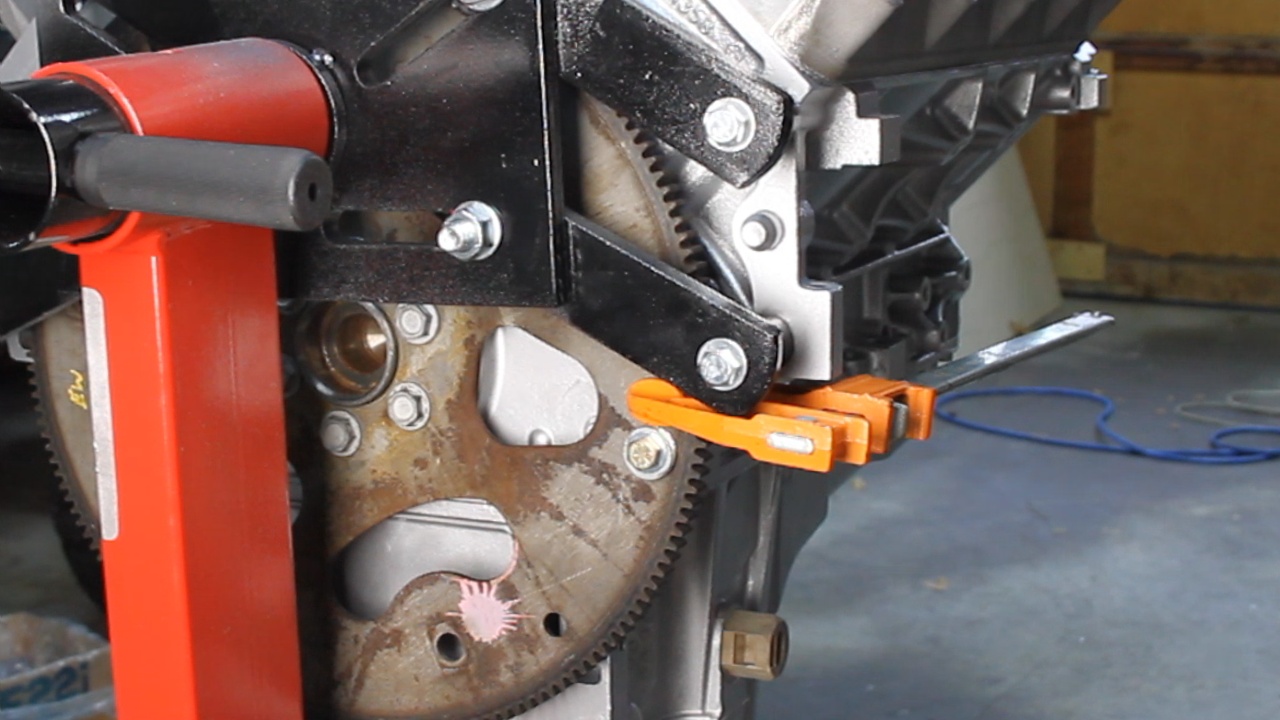
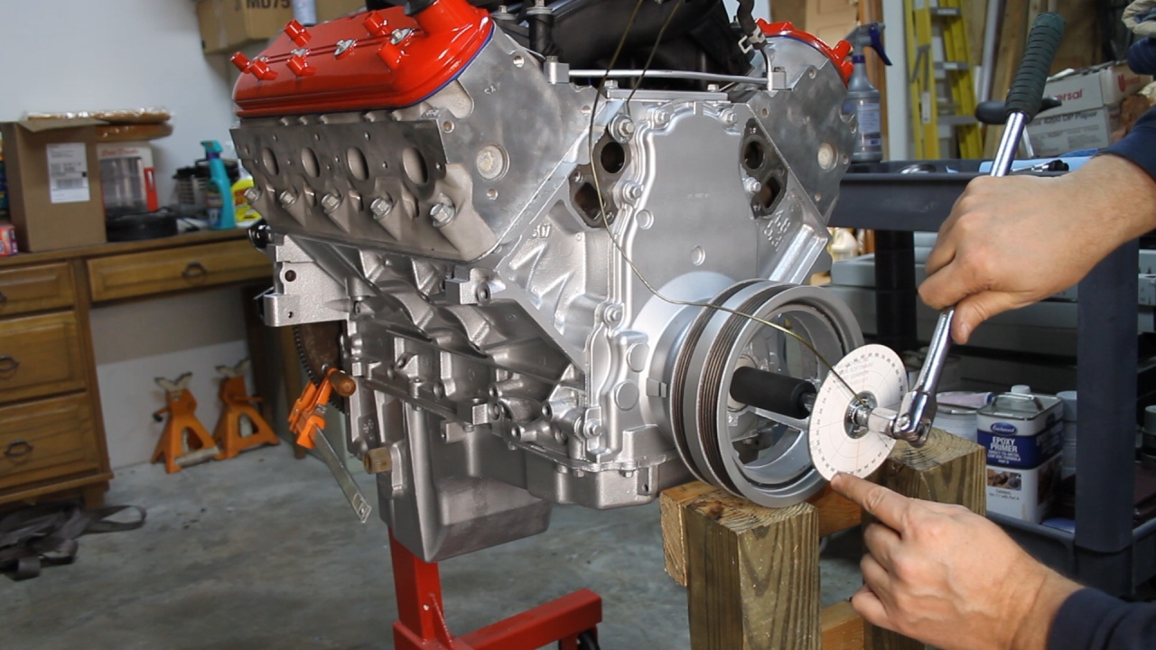
To help with the installation of the Harmonic Balancer, I temporarily re-installed the original Flexplate (I will not be using this) and installed a temp bolt, and clamp to create an interference to lock the Crankshaft. Who needs a special tool... I've had this clamp for years and it worked fantastic.
Next, I installed the Harmonic Balancer. First I used a long special bolt to get it started, then swapped to the Old original bolt and torqued to 240ftlbs, then swapped to the New Bolt. This gets torqued to 37ftlbs and then another 140 degrees. How about that DIY Torque Angle Gauge? an old CD and a protractor image I found on the internet.
Here is where we are.... Starting to look like an engine again!
Hope you're enjoying the progress!
Took some time to do some careful masking and then took the Paint to it! In this photo, I am applying the 3rd coat of paint to the main assembly. I decided to mask off the Heads and leave them unpainted to show off the natural aluminum finish.
After painting with VHT high temp paint, I used a small electric heater to help partially bake it on. Over several hours, I moved the heater to help bake different areas of the assembly.
Next, the Valley Pan cover and Knock Sensors were installed.
Are you ready? Here I am installing the Vavle covers. These were painted separately and baked in the oven. Wasn't sure if I was going to like this, but after installing them, I think it turned out really good. The Jeep is going to be Red and I thought this small touch, would help tie it all together.
After installing the new Knock Sensor wiring harness, I followed the GM TSB and added a small silicone dam to help divert water around the sensor locations. Water does not play nicely with the sensors.
Next, it was time for the Coolant Vent Block offs in the rear and Tube in the front.
After putting on the new FelPRO Intake Gaskets, I installed and torqued down the Intake
Here the new Throttle Body Gasket gets installed
To help with the installation of the Harmonic Balancer, I temporarily re-installed the original Flexplate (I will not be using this) and installed a temp bolt, and clamp to create an interference to lock the Crankshaft. Who needs a special tool... I've had this clamp for years and it worked fantastic.
Next, I installed the Harmonic Balancer. First I used a long special bolt to get it started, then swapped to the Old original bolt and torqued to 240ftlbs, then swapped to the New Bolt. This gets torqued to 37ftlbs and then another 140 degrees. How about that DIY Torque Angle Gauge? an old CD and a protractor image I found on the internet.
Here is where we are.... Starting to look like an engine again!
Hope you're enjoying the progress!
Last edited by UcanDoIt2; May 8, 2017 at 10:40 PM.
Thread Starter
Teching In
Joined: May 2014
Posts: 39
Likes: 1
Here is a short video that covers the current progress in detail. This covers the following: Paint, Valley pan cover, Knock Sensors, Knock Sensor Harness and Dam, Intake, Coolant Vents/Block offs, Valve Covers, and Harmonic Balancer installations.

Thread Starter
Teching In
Joined: May 2014
Posts: 39
Likes: 1
More progress on the LM7!
Installed all of the Sensors. This included the Crankshaft Position Sensor, Camshaft Position Sensor, Oil Pressure Sensor, Coolant Temperature Sensor, and Manifold Ambient Pressure Sensor.
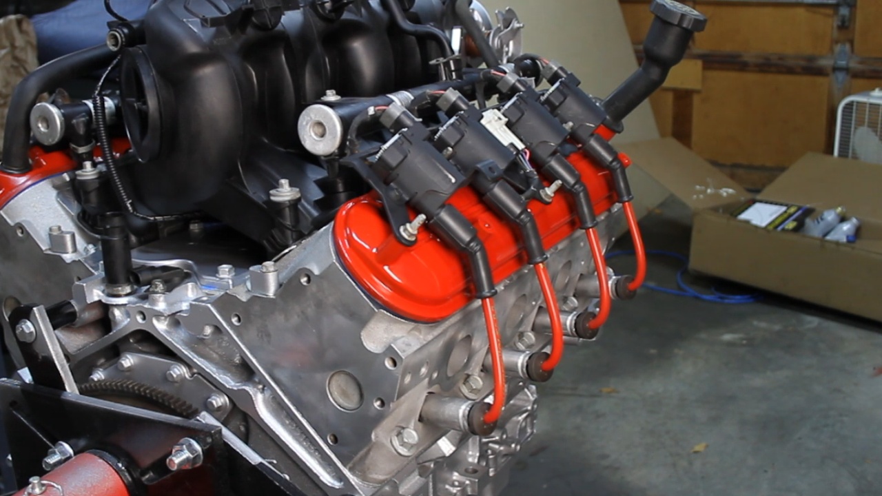
Next, we installed the Coil Packs, Spark Plugs and Plug Wires.
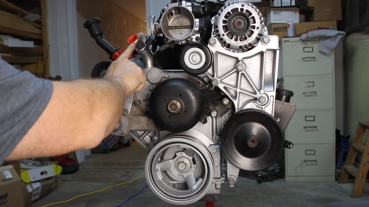
Now it was time to move to the accessories. The Vortec Truck engines have a tall Intake Manifold that positions the Throttle Body in an elevated position. Due to this relationship, the Vortec engines typically use a Water Pump that exits from the top as seem in this picture. I have temporarily installed the original Water Pump.
While ordering parts, I made the decision that I wanted to swap to an LS3 Water Pump which exits on the Driver's Front side of the water pump. This locates it closer to the Inlet port on the radiator (inlet on the upper driver's side). I had ordered these parts back when the engine was at the Machine Shop. What I did not realize was that the Vortec Accessory bracket placed the Idler Pulley in the same location as the water pump exit port. You can see the conflict in this picture.
Just after wigging out! :rofl: I went back for some more research looking for another solution. I ran across a Relocation Bracket that is fabricated by Dirty Dingo Motorsports. This bracket relocated the Idler Pulley for an LS2 style water pump which exits the Front Passenger side of the pump. We are getting close!!!! I called and spoke to Tony at DDM and it was determined that what I was wanting to do with the LS3 Pump would work. Here, I took off the Accessory Bracket and installed the desired LS3 Water Pump.
Then I held up the Accessory Bracket to show the overlap. You can see where the Idler Pulley causes an interference with the exit port. The DDM Relocation Bracket will allow me to relocated the Idler Pulley to the center of the Accessory Bracket and then I can remove the portion of the bracket that causes the interference.
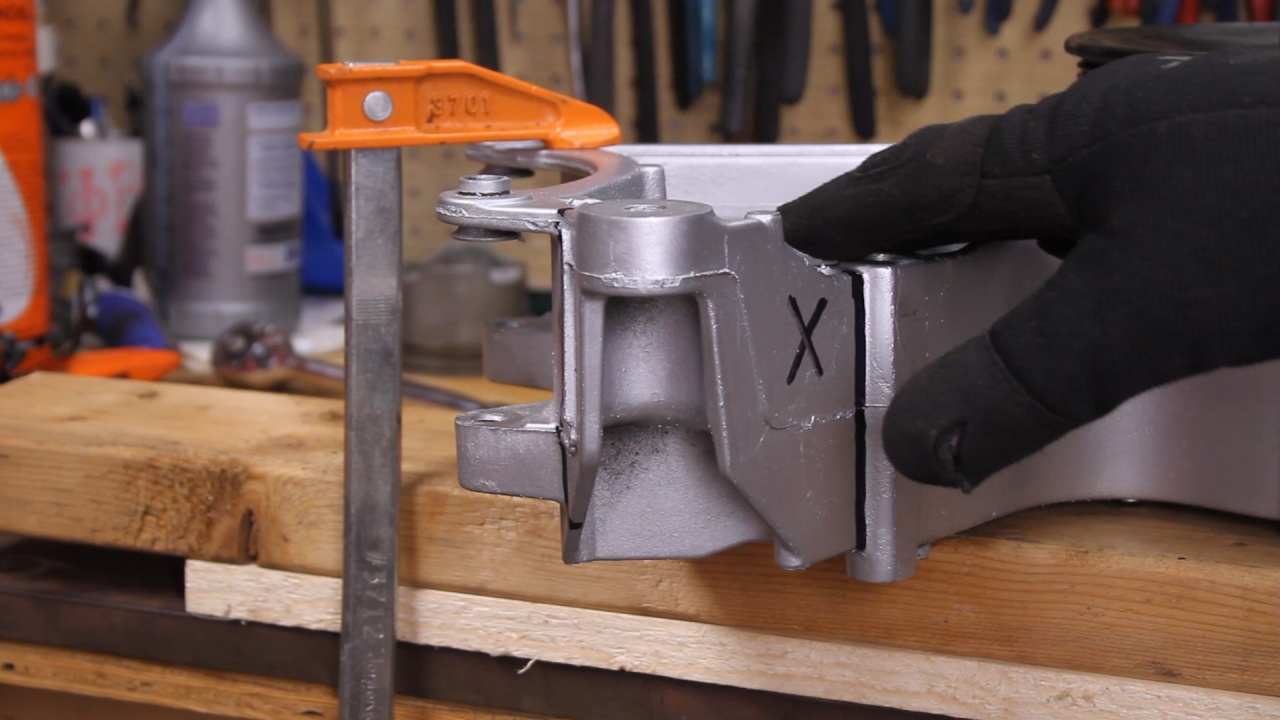
Here, I have marked the area on the bracket that I plan to remove.
Here, I am cutting through the lower plate.
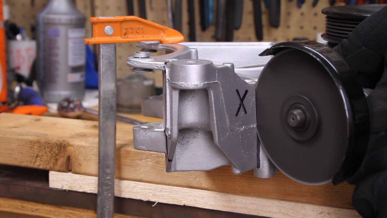
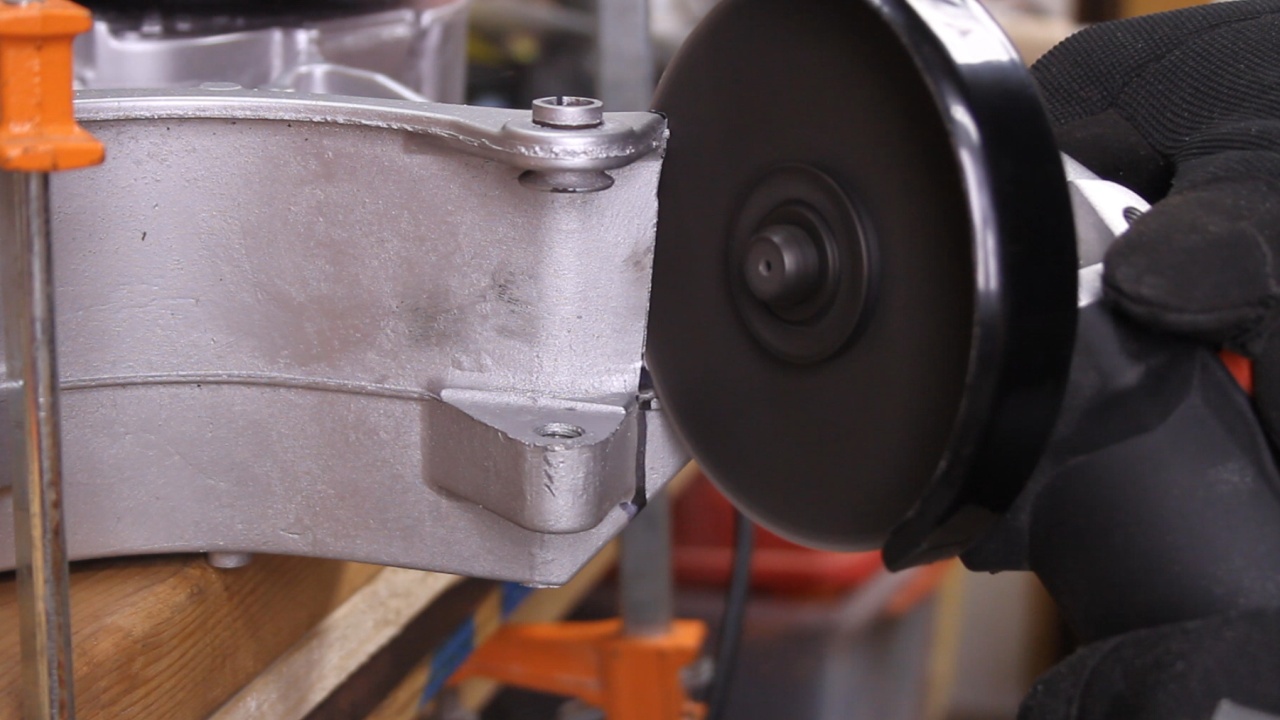
Here, I am cutting through the upper plate.
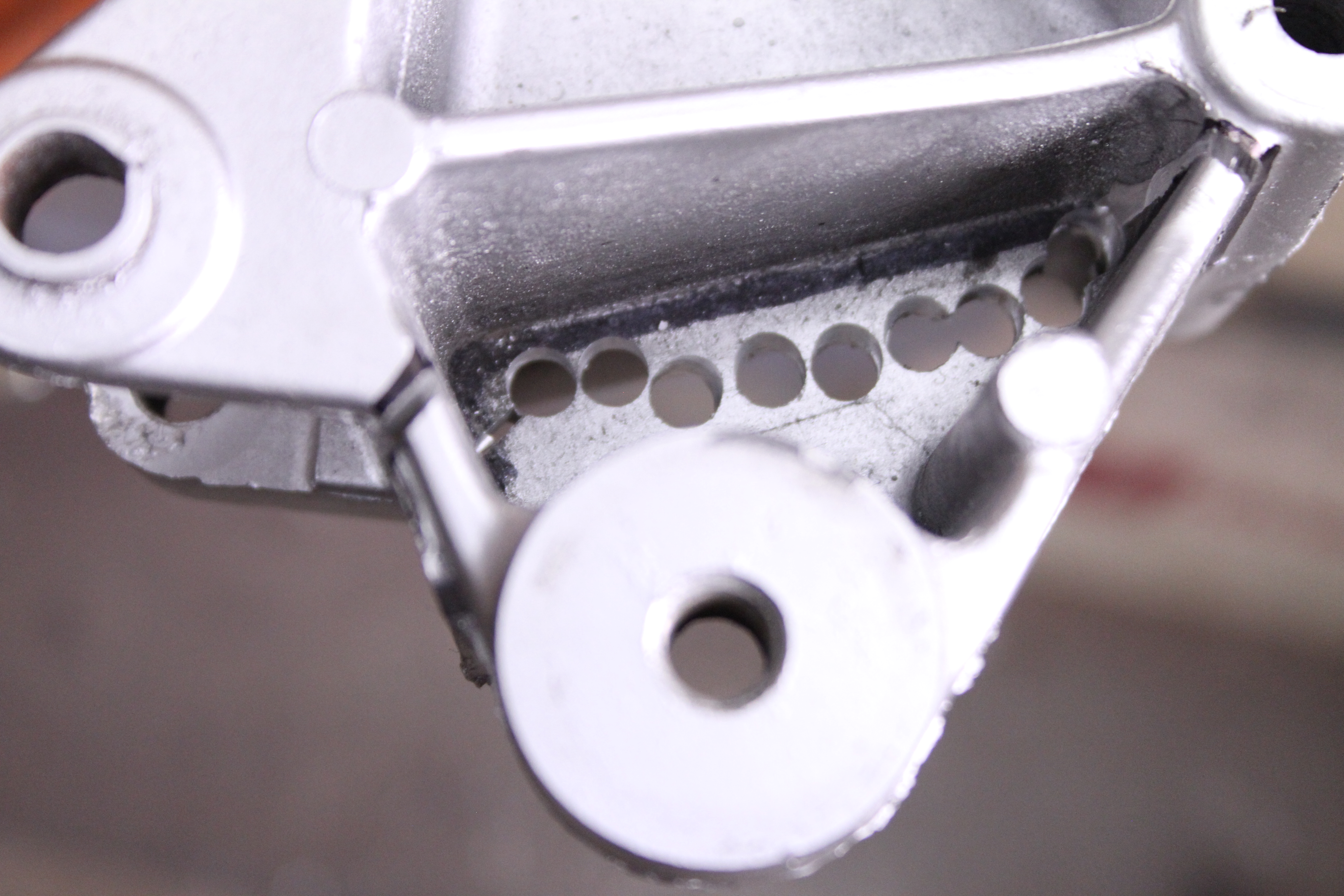
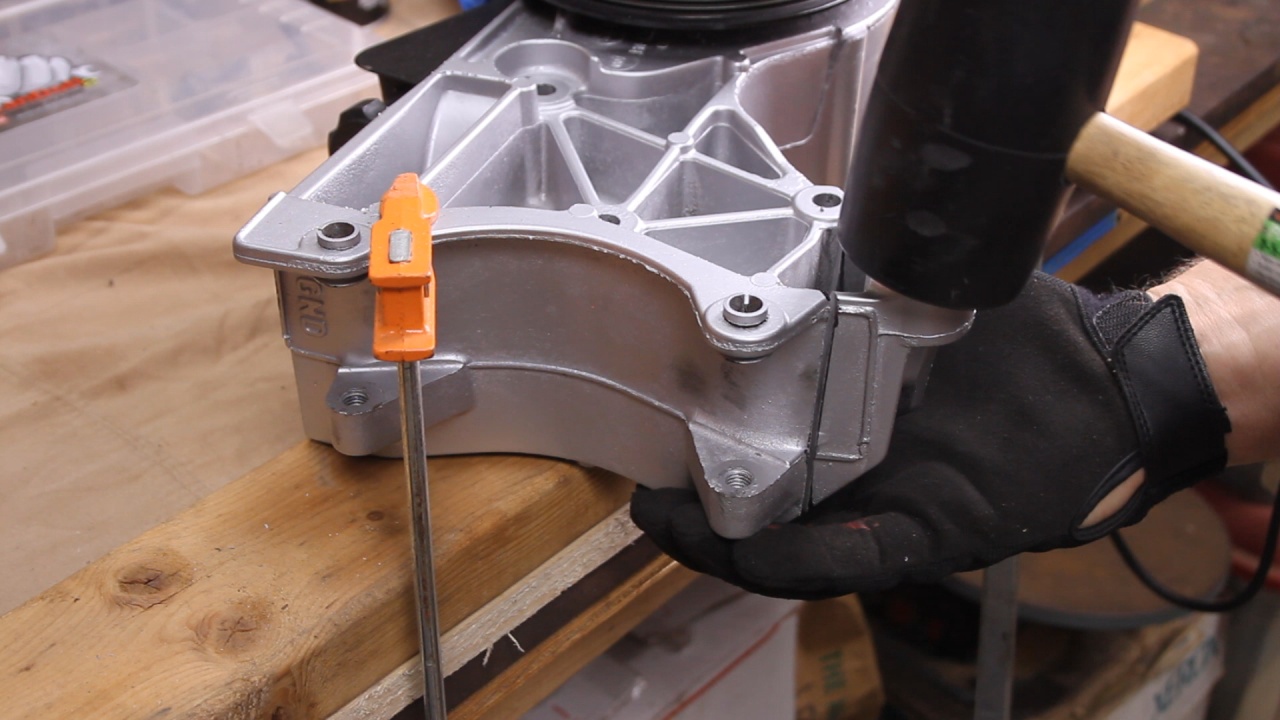
The center plate was tough to get to with the cutoff wheel, so I drilled adjacent holes to weaken the plate and then used a rubber hammer and a simple tap to remove this piece.
A little grinding to make it look professional and it was starting to look sharp!
Now it all appears to fit like I want it.
I am waiting for the DDM Bracket to arrive and I also am having to purchase a new Tentioner Pulley that will mount on the upper left side of the Water Pump. Both are due to arrive in the next two days. This will wrap up the physical build of this LM7 Engine.
The next large task for this engine will be alterations to the Wiring Harness to remove unwanted wires (Auto Transmission and others) and create a 4-wire standalone solution.
Installed all of the Sensors. This included the Crankshaft Position Sensor, Camshaft Position Sensor, Oil Pressure Sensor, Coolant Temperature Sensor, and Manifold Ambient Pressure Sensor.
Next, we installed the Coil Packs, Spark Plugs and Plug Wires.
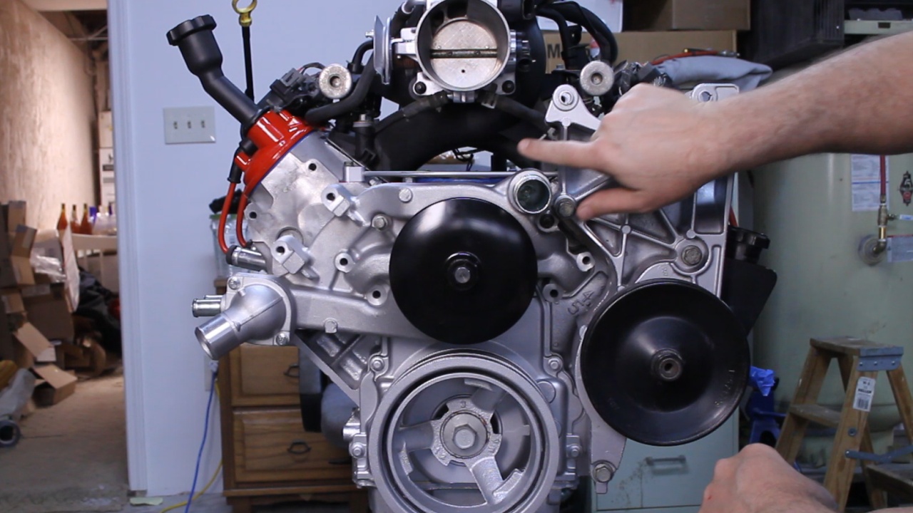
Now it was time to move to the accessories. The Vortec Truck engines have a tall Intake Manifold that positions the Throttle Body in an elevated position. Due to this relationship, the Vortec engines typically use a Water Pump that exits from the top as seem in this picture. I have temporarily installed the original Water Pump.
While ordering parts, I made the decision that I wanted to swap to an LS3 Water Pump which exits on the Driver's Front side of the water pump. This locates it closer to the Inlet port on the radiator (inlet on the upper driver's side). I had ordered these parts back when the engine was at the Machine Shop. What I did not realize was that the Vortec Accessory bracket placed the Idler Pulley in the same location as the water pump exit port. You can see the conflict in this picture.
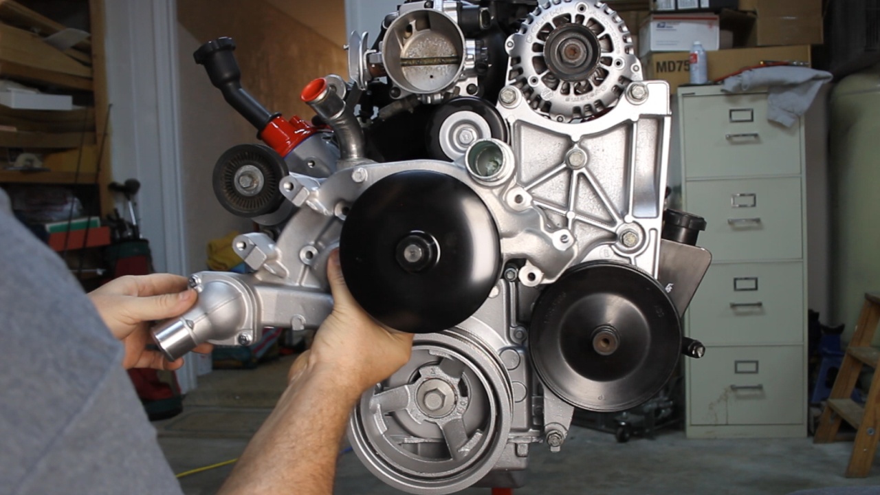
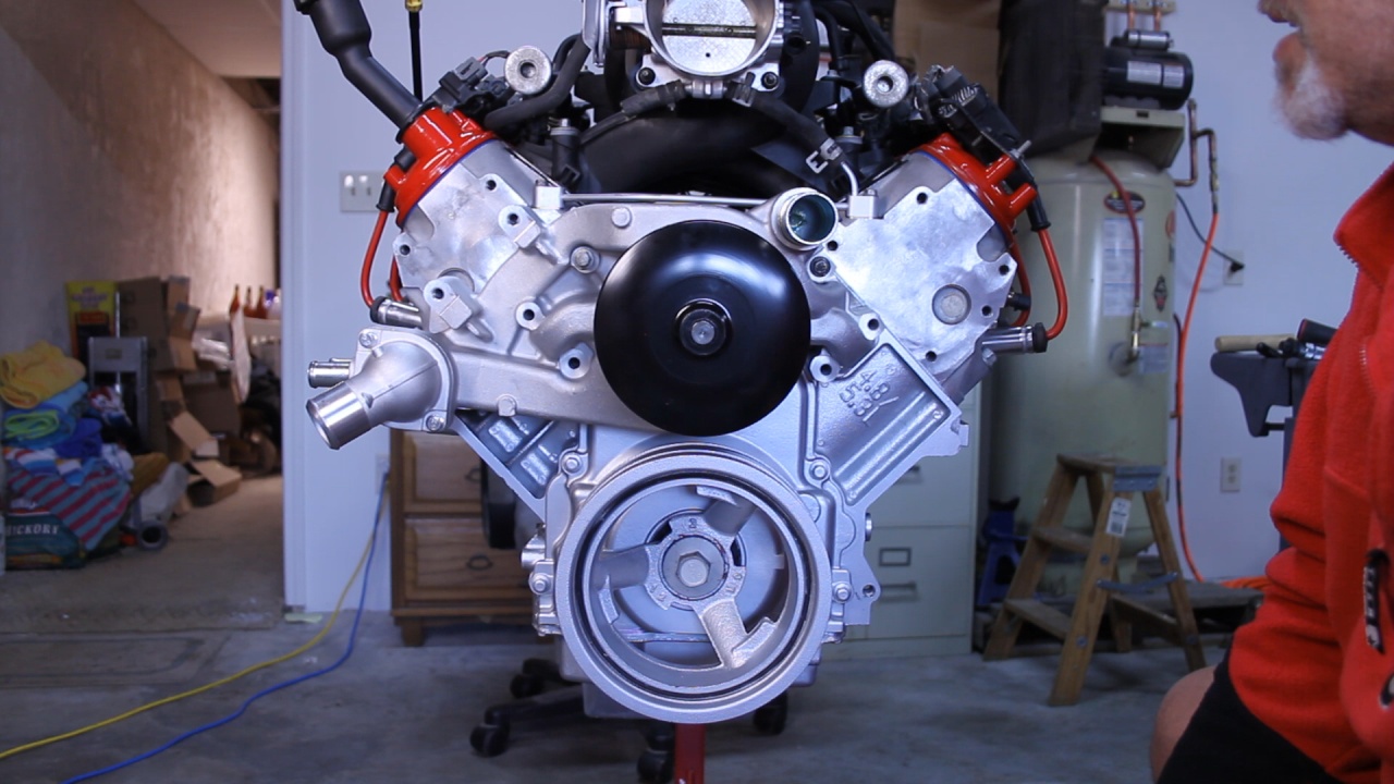
Just after wigging out! :rofl: I went back for some more research looking for another solution. I ran across a Relocation Bracket that is fabricated by Dirty Dingo Motorsports. This bracket relocated the Idler Pulley for an LS2 style water pump which exits the Front Passenger side of the pump. We are getting close!!!! I called and spoke to Tony at DDM and it was determined that what I was wanting to do with the LS3 Pump would work. Here, I took off the Accessory Bracket and installed the desired LS3 Water Pump.
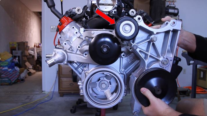
Then I held up the Accessory Bracket to show the overlap. You can see where the Idler Pulley causes an interference with the exit port. The DDM Relocation Bracket will allow me to relocated the Idler Pulley to the center of the Accessory Bracket and then I can remove the portion of the bracket that causes the interference.
Here, I have marked the area on the bracket that I plan to remove.
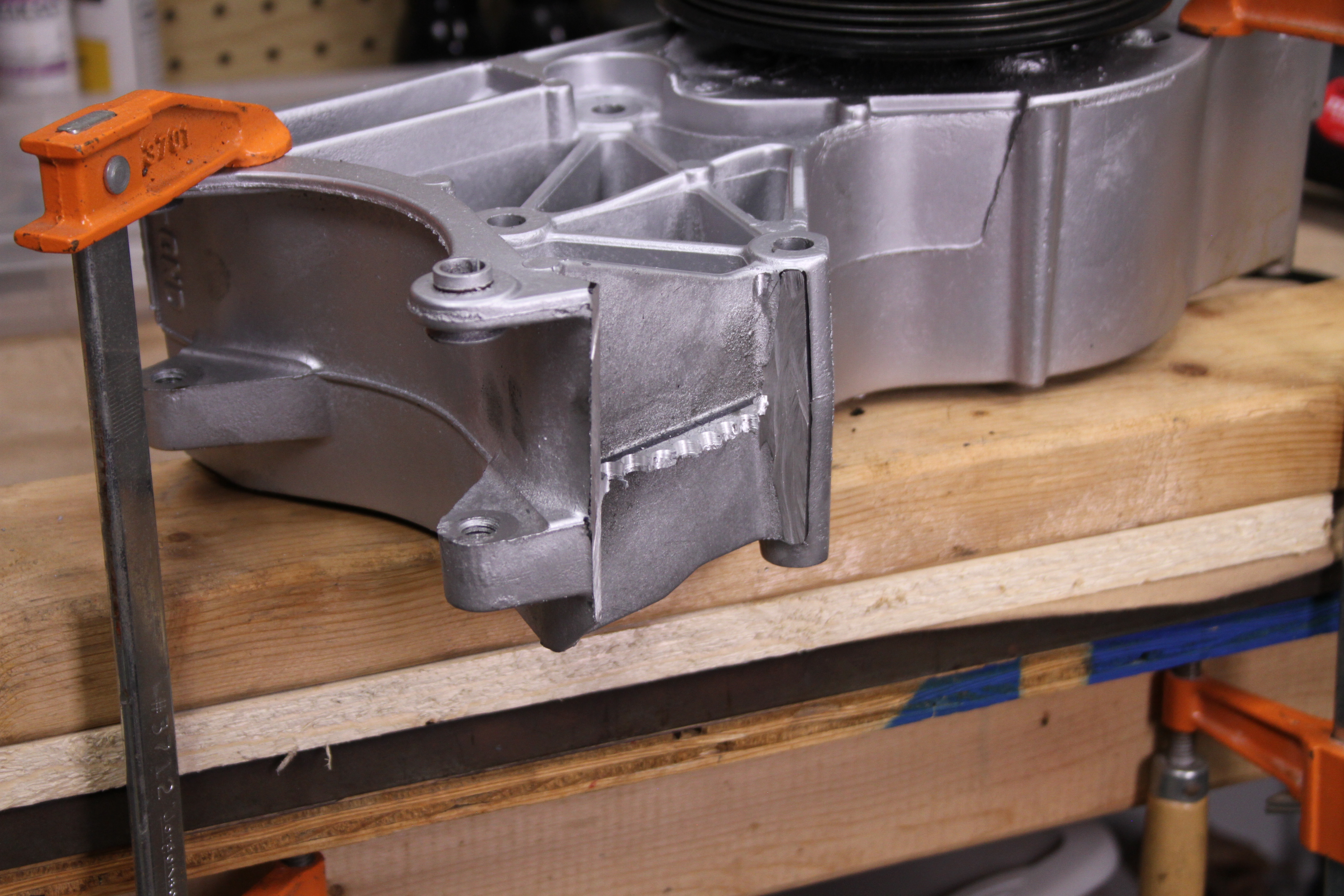
Here, I am cutting through the lower plate.
Here, I am cutting through the upper plate.
The center plate was tough to get to with the cutoff wheel, so I drilled adjacent holes to weaken the plate and then used a rubber hammer and a simple tap to remove this piece.
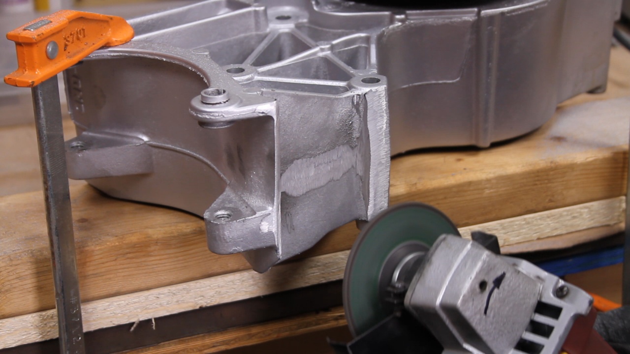
A little grinding to make it look professional and it was starting to look sharp!
Now it all appears to fit like I want it.
I am waiting for the DDM Bracket to arrive and I also am having to purchase a new Tentioner Pulley that will mount on the upper left side of the Water Pump. Both are due to arrive in the next two days. This will wrap up the physical build of this LM7 Engine.
The next large task for this engine will be alterations to the Wiring Harness to remove unwanted wires (Auto Transmission and others) and create a 4-wire standalone solution.
Last edited by UcanDoIt2; May 8, 2017 at 10:41 PM.


