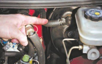
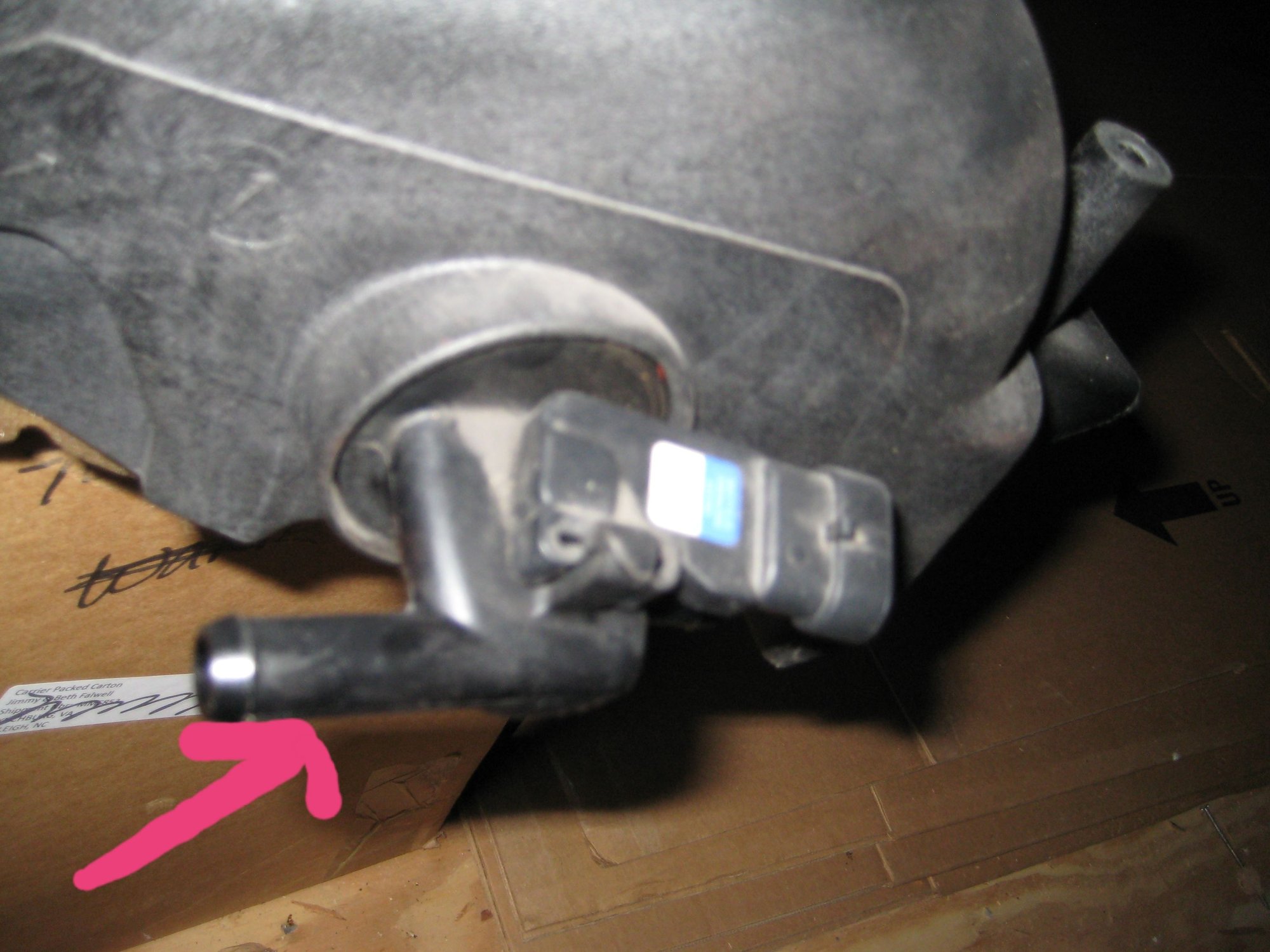
LS1 vacuum pipe schematic
#1
Teching In
Thread Starter
Hi I'm building a UK spec AC Cobra replica which has a brand new LS1 engine. I'm installing a Painless Performance EFI and am in the final stages of finishing the engine off. It seems that the vacuum pipe needs to run from the back of the TB to the servo or is the pick up from somewhere else? Any help/advice much appreciated.
#2
TECH Senior Member
You mean brake booster? Vacuum is taken from the rear of the manifold. No pipe, all hose.
#3
Teching In
Thread Starter
My bad, vacuum hose.
Going to what we call the brake servo and I guess you call the brake boost.
Is the port for this hose on the rear drivers side of the engine?
Thanks
Going to what we call the brake servo and I guess you call the brake boost.
Is the port for this hose on the rear drivers side of the engine?
Thanks
The following 2 users liked this post by 98CayenneT/A:
chrisfreemanuk (02-14-2020), G Atsma (02-14-2020)


