


Crane Rocker Arms
Originally Posted by Mark Campbell
Hey Guys, Thanks for all of the interest in the new products we are making for the LS1. Both of you are right about the products you have discussed. Gold Z is correcct in stating that we have recently released new "long travel" hydraulic roller and mechanical roller lifters for the LS1. (Part # 144510-16 for mechanical rollers and #144535-16 for the hydraulic rollers...both are in stock and ready for shipping). The bodies are made from "carburized" billet steel for strength and the oil band has been relocated and sized to allow up to .700 valve lift (when using 1.7 rockers, more with 1.8s or 1.9s). This relocation of the oiling band prevents the band from dropping out of the bottom of the lifter bore on (small basecircle) high lift camshafts which would result in loss of oil pressure. Of course, these lifters have premium quality wheels, axles and bearings. The hydraulic roller lifter is designed to work with .060"-.100" preload and we know it will be quiet. This lifter incorporates our 4th iteration of internal oiling in a hydraulic roller lifter. It's interesting to note that one of the hydraulic roller lifters that is highly acclaimed on this site is an exact copy of our 1st design. Oops! Maybe I've just given out too much info and they will look at the improvements in these new "long travel" lifters!!
As far as shaft mount rockers go, XTooper is right. Where did you hear that XTrooper? You must have an "in" at "rumor control"!!! We didn't pursue shaft-mounts for the LS1 for quite a while for two reasons:1) for the most part there is no advantage to shaft mounts until you get over 450# open pressure. We have had dozens of field tests showing that our LS1 Gold Race rockers produce more RWHP than what many consider the best shaft mounts. 2) our investigations have shown that there is no reasonable way to make a "bolt on" shaft mount that has proper rocker geometry to provide anything close to what we term "Quick-Lift"... that is why our stud mounts have made more power!! After several design exercises, we have developed a design of shaft mounts using our Polymer Matrix Composite bearings that we feel will be the ultimate in "Quiet, Quick-Lift" design. They will not be bolt ons, but will require removal of the heads, and some elementary machining. They will be available in 1.7, 1.75, 1.8, 1.85, and 1.9 advertised ratios (of course being Quick-Lift designs, they will start the valve off the seat at a ratio of at least .1 higher than advertised) We expect they will be used by people wanting the best and willing to do what is necessary to take advantage of the design. They might fit under stock valve covers, but that can't be promised yet. In all honesty, we are probably 4-6 months from production and I don't have any ballpark price, yet. I can guarantee they will make power and be quieter than stock!! Hope this info helps. I probably will start a thread in the next few days highlighting the new lifters . Again, Thanks for your interest in our products!
Mark Campbell
VP, R&D
Crane Cams, Inc.
Mark,
Why do you guys not label the Rocker Arms / Shaft Mounts with the higher than normal ratio rockers as such? I'm not the only one to run into this, Jesel does the same thing on shaft mounts too, and when you use the rockers in a application that is lift restricted due to rules or you are pushing the coil bind barrier this can cause issues.
If it's a 1.72, just list it as that. It's simple, causes less issues and I don't think customers will view it as a negaitve since this a industry where the average joe thinks bigger is better. Might be because most of us are men and "average" is just what most guys have.... sorry gotta throw some Freud in there.
Bret

Staging Lane
Joined: Apr 2004
Posts: 58
Likes: 0
Originally Posted by SStrokerAce
Mark,
Why do you guys not label the Rocker Arms / Shaft Mounts with the higher than normal ratio rockers as such? I'm not the only one to run into this, Jesel does the same thing on shaft mounts too, and when you use the rockers in a application that is lift restricted due to rules or you are pushing the coil bind barrier this can cause issues.
If it's a 1.72, just list it as that. It's simple, causes less issues and I don't think customers will view it as a negaitve since this a industry where the average joe thinks bigger is better. Might be because most of us are men and "average" is just what most guys have.... sorry gotta throw some Freud in there.
Bret
Why do you guys not label the Rocker Arms / Shaft Mounts with the higher than normal ratio rockers as such? I'm not the only one to run into this, Jesel does the same thing on shaft mounts too, and when you use the rockers in a application that is lift restricted due to rules or you are pushing the coil bind barrier this can cause issues.
If it's a 1.72, just list it as that. It's simple, causes less issues and I don't think customers will view it as a negaitve since this a industry where the average joe thinks bigger is better. Might be because most of us are men and "average" is just what most guys have.... sorry gotta throw some Freud in there.
Bret
The reason we label a 1.7 rocker a 1.7 is that we can guarantee that as a minimum ratio depending on deflection due to spring load or screwed up geometry due to improper pushrod length. If things are right, the customer will probably end up at 1.72-1.74. Because the final ratio (under spring load) is also dependent on pushrod length, it is necessary to physically check clearances as much as possible. And I haven't even begun to discuss valve control issues due to valve "lofting" due to flexible pushrods, lobe design, lobe/spring compatibility, etc. (Most LSx engines running over 5000 RPM are experiencing at least .020" valve loft. The lifter isn't really following the lobe then. Fortunately, for P to v issues this is happening at a point where the piston is pretty far down the hole!)
In closing, as a continuation of my opening point, there are so many variables that affect items that we "assume" to be exact that there is no way to guarantee an exact rocker ratio. This is why some people check things out and are successful and knowledgeable and some people want to believe what they want to believe and have occasional setbacks! At Crane we are trying to put out as much info as we can explaining our "Quick-Lift" geometry. (Much of that info is available at www.cranecams.com). Some people think we are that this "quick-lift" is smoke and mirrors. It isn't, it's applied geometry. We are having tremendous success with this concept and as improved materials permit, we will continue to push accelerated valve lift as far as we can without compromising reliability.
Mark Campbell
Mark,
I can understand the fact that it might not reach the maximum lift due to deflection but for those of us who work to make it work dynamically as well as possible with the right pushrods etc.... the Ratio at Max lift should be by far the rated rocker ratio... I don't care what it is below that for the most part in terms of rating (in performance its a different story) but it's a pain in the *** when you get parts for a valvetrain and expect xxx amount of lift and now are going .015" farther into your coil bind cushion because of some marketing BS. When you take up 25-30% of my coil bind clearance and I have to redesign the valvetrain or get different rocker arms, guess which one guys are going to pick most times? Last thing I'm going to do is by Ti valves or hollow stems valves so I can loosen up the installed height on the valve spring.
Add on top of that the aggressive profiles that are being used on the LS motors and the loft that comes with them when you don't have the proper parts matched to them and this higher than advertised ratio starts breaking springs due to coils smacking into each other... with single springs that makes a big mess of pistons and valves... To me that's just dumb and is going to get customers pissed off at you. They don't understand why it happens nor do they care, they will just bad mouth you on the internet and hurt your bottom line in that application/market.
It doesn't make sense to me in either application or business.
It would be nice if checking the valvetrain in a static engine build room replicated the dynamic condition but as you know only a spintron can tell you what's actually happening.
How about what happens to the valve spring requirements with something like this "quick lift" technology? Team it up with a more aggressive lobe profile and your going to need even more spring = more deflection.... Part of me wonders why the trend has to been toward more aggressive valve action on hyd roller GM motors when most times it causes issues at higher RPM for guys and produces unwanted effects such as valvetrain noise, lower part life and unstable valve motion and valve bounce on the seat at the RPM where these guys want to make power?
What are you doing in terms of reliability to the rest of the valvetrain in terms of the Quick Lift Technology.... I've always evaluated newer technologies in the valvetrain area and used them when I saw results and the physics of the technology pay off.... ex) lighter parts are easier to control etc....
Sorry man just my rant and what I see works and what doesn't.
Bret
Staging Lane
Joined: Apr 2004
Posts: 58
Likes: 0
Hey Stroker, calm down and check some things out. First off you didn't clearly read what I wrote. I can change the effective rocker ratio at max lift with pushrod length. Unless you have set up an apparatus like I discussed and tried this with several different pushrod lengths and plot the lift curves, you will think I am full of it. Secondly, you can't depend on what a Spintron tells you because you aren't opening the exhaust into cylinder pressure and you don't have suction trying to pull the exhaust open on the intake stroke as well as a lot of other simple but important subtleties. Finally, do the math of a simple lever arm and you will find that the "quick-lift" geometry reduces the need for high seat pressures. All sorts of good things are happening spring wise with quick-lift geometry. If you don't think they do, it is because you haven't tried it.
As I stated before, the exact effective ratio is going to vary slightly because of a lot of things. I have seen production variations from other rocker manufacturers result in variations of as much as .030" gross valve lift due to manufacturing tolerances in the same set of 16 rockers!! Have you ever bothered to check something like that out!! Do you bother to degree in each lobe of 16 on a cam? I guarantee that if you do that you will see variations that will really get you hot! Most people degree in #1 and assume the rest are correct and in the proper phase!! Check out others and then check out Crane!!
As far as the variation in lift goes with rockers, most enginebuilders settle into using a given brand of rockers and learn how they work out with respect to lift.. People with lots of experience check this out regularly. I can only state again that our rockers are all slightly overbuilt with respect to ratio so that we can guarantee a minimum ratio under the worst circumstances. If we didn't do that and you ended up with less than the advertised ratio, you might be accusing us of cheating you!! For a manufacturer, it's often a "no-win" situation. We do the best we can to make the best performing, most reliable products we can. Some people like them and some people won't. You vote with your dollars. We know we can't please everybody, but we keep trying! Have a good day!!
Mark Campbell
To start I like having a good ear to chew on.....
No I don't think your full of it, but what's going on with the rest of the geometry and the loading of the valve guide in the other pushrod lengths in that situation?
Rather than make a general statement about it, just list what changes YOU see when you change PR length with said rocker arm in the lift curve change. I could go out in the shop and do it, but I've got other things to do today.
IMHO if the seated spring pressures are pulling the exhaust valve open during the intake stroke (around .400-.500 lift on the opening side is the highest vacuum in the intake port) then you have more problems when it comes to closing the exhaust valve and valve bounce than you can imagine I would fix that first....
To me the Spintron is the biggest invention fueling the increase in HP that we have seen since the Flow Bench and Dyno. It's directly related to increasing the understanding of valvetrain dynamics and increased RPM levels we see today. Hell before we ran 5/16 PR's because they were lighter, now a 1/2" or 7/16 PR in Chromoly PR is in there in place of it and the motors turn higher and break less... and now we know why. Yeah it has it's drawbacks just like a flow bench does, but yet you learn more with it than without it.
Hey man I'm not the one selling these things... I can do the math but not now. You're the guy who makes the coin on these and where I come from support your claims with some math or physics and go from there...
Ok back at it...
Next set of Rockers I put on something I will check with a dial indicator on the same hole/valve. Might as well take out all the variables.
My big concern is that you can send something to someone across the country and if they follow your instructions on install height and assembly, checking the correct tolerences etc... the thing will run as planned. From what I have seen that's the hardest thing to do due to lack of knowledge on a lot of customers.... Big hurdle for anyone which I'm sure you know.
You send me a lobe catalog and then give me the same price point I use with other guys and I'll throw one of yours on the Cam Dr be glad to check them out... I like who I work with now because I get the service, technology, accuracy for the $$ we are spending for the average guy and parts that I want out of them.... Nothing wrong with you guys, but I don't get the same things with you that I get other places... I would have to get seriously POed at who I use now to change from them.
BTW I'd love to degree in every lobe, but unfortunatly they are all tied together. 1 & 6 I will do on a assembly and almost every time I get the same ICL for both, I can't ask for more than that. What I'm more concerned about is that the lobe profile is made as close to the design as possible, getting accurate valvetrain dynamics is harder than getting things within 1 deg, but from what I am seeing lately the accuracy is within 1/4 of that.
I agree with you fully on this.
Honestly I'd like to see one of your new lifters since you can run over .400" at the lobe with them in a LS1 block is a good idea... As long as they last longer than the ole 11522 lifters, I've seen too many guys I need of a lifter bore rebushing because they ran too much pressure on those things on a street car.... Lift is always a good advantage here, but man if the needle bearings lock up I could care less.
Don't take that as a knock, I've had some Comp 875-16's go out lately due to what I think is some bad heat treating on the plunger retainer in them, either way good heat treating is hard to get but you guys as companies have beat the snot out of the lifter manufacture pretty bad so I wouldn't be suprised to see corners get cut on their part here under new management.
I'd like to look over these rockers.... The part that gets me is this
"Next (this is where the Quick-Lift technology kicks in), the stockers ratio when the valve leaves its seat is 1.52 while the Crane's is 1.82 all the way up to ~.300" of valve lift! Then as the valve starts to close, at ~.300" the Crane ratio again increases to 1.82 while the stocker decreases to 1.52." '
How is that not loading the lifter and pushrod more, pushrod forces and deflection are definately increased here? Plus you are opening and closing the valve faster over the nose as well so the only place where it looks like the valve motion isin't more aggressive is on the flanks of the cam where it's realtively calm unless it's a inverted flank cam? Increasing the rocker ratio in the transition periods is going to create more pushrod, stud, rocker deflection.
Don't get defensive just explain that to me. That's all I'm asking, makes for a good discussion on a post like this.
Bret
Originally Posted by Mark Campbell
Hey Stroker, calm down and check some things out. First off you didn't clearly read what I wrote. I can change the effective rocker ratio at max lift with pushrod length. Unless you have set up an apparatus like I discussed and tried this with several different pushrod lengths and plot the lift curves, you will think I am full of it.
Rather than make a general statement about it, just list what changes YOU see when you change PR length with said rocker arm in the lift curve change. I could go out in the shop and do it, but I've got other things to do today.
Originally Posted by Mark Campbell
Secondly, you can't depend on what a Spintron tells you because you aren't opening the exhaust into cylinder pressure and you don't have suction trying to pull the exhaust open on the intake stroke as well as a lot of other simple but important subtleties.
To me the Spintron is the biggest invention fueling the increase in HP that we have seen since the Flow Bench and Dyno. It's directly related to increasing the understanding of valvetrain dynamics and increased RPM levels we see today. Hell before we ran 5/16 PR's because they were lighter, now a 1/2" or 7/16 PR in Chromoly PR is in there in place of it and the motors turn higher and break less... and now we know why. Yeah it has it's drawbacks just like a flow bench does, but yet you learn more with it than without it.
Originally Posted by Mark Campbell
Finally, do the math of a simple lever arm and you will find that the "quick-lift" geometry reduces the need for high seat pressures. All sorts of good things are happening spring wise with quick-lift geometry. If you don't think they do, it is because you haven't tried it.
Ok back at it...
Originally Posted by Mark Campbell
As I stated before, the exact effective ratio is going to vary slightly because of a lot of things. I have seen production variations from other rocker manufacturers result in variations of as much as .030" gross valve lift due to manufacturing tolerances in the same set of 16 rockers!! Have you ever bothered to check something like that out!!
My big concern is that you can send something to someone across the country and if they follow your instructions on install height and assembly, checking the correct tolerences etc... the thing will run as planned. From what I have seen that's the hardest thing to do due to lack of knowledge on a lot of customers.... Big hurdle for anyone which I'm sure you know.
Originally Posted by Mark Campbell
Do you bother to degree in each lobe of 16 on a cam? I guarantee that if you do that you will see variations that will really get you hot! Most people degree in #1 and assume the rest are correct and in the proper phase!! Check out others and then check out Crane!!
BTW I'd love to degree in every lobe, but unfortunatly they are all tied together. 1 & 6 I will do on a assembly and almost every time I get the same ICL for both, I can't ask for more than that. What I'm more concerned about is that the lobe profile is made as close to the design as possible, getting accurate valvetrain dynamics is harder than getting things within 1 deg, but from what I am seeing lately the accuracy is within 1/4 of that.
Originally Posted by Mark Campbell
As far as the variation in lift goes with rockers, most enginebuilders settle into using a given brand of rockers and learn how they work out with respect to lift.. People with lots of experience check this out regularly. I can only state again that our rockers are all slightly overbuilt with respect to ratio so that we can guarantee a minimum ratio under the worst circumstances. If we didn't do that and you ended up with less than the advertised ratio, you might be accusing us of cheating you!! For a manufacturer, it's often a "no-win" situation. We do the best we can to make the best performing, most reliable products we can. Some people like them and some people won't. You vote with your dollars. We know we can't please everybody, but we keep trying! Have a good day!!
Honestly I'd like to see one of your new lifters since you can run over .400" at the lobe with them in a LS1 block is a good idea... As long as they last longer than the ole 11522 lifters, I've seen too many guys I need of a lifter bore rebushing because they ran too much pressure on those things on a street car.... Lift is always a good advantage here, but man if the needle bearings lock up I could care less.
Don't take that as a knock, I've had some Comp 875-16's go out lately due to what I think is some bad heat treating on the plunger retainer in them, either way good heat treating is hard to get but you guys as companies have beat the snot out of the lifter manufacture pretty bad so I wouldn't be suprised to see corners get cut on their part here under new management.
I'd like to look over these rockers.... The part that gets me is this
"Next (this is where the Quick-Lift technology kicks in), the stockers ratio when the valve leaves its seat is 1.52 while the Crane's is 1.82 all the way up to ~.300" of valve lift! Then as the valve starts to close, at ~.300" the Crane ratio again increases to 1.82 while the stocker decreases to 1.52." '
How is that not loading the lifter and pushrod more, pushrod forces and deflection are definately increased here? Plus you are opening and closing the valve faster over the nose as well so the only place where it looks like the valve motion isin't more aggressive is on the flanks of the cam where it's realtively calm unless it's a inverted flank cam? Increasing the rocker ratio in the transition periods is going to create more pushrod, stud, rocker deflection.
Don't get defensive just explain that to me. That's all I'm asking, makes for a good discussion on a post like this.
Bret
Last edited by SStrokerAce; May 17, 2005 at 02:58 PM.
Fantastic discussion guys.
Doesn't the quick lift rocker revert to advertised ratio after ~.300 lift as it rolls over the nose and then back to 1.8 or whatever the spec is as it rolls to the the backside @ ~.300 lift.
Doesn't the quick lift rocker revert to advertised ratio after ~.300 lift as it rolls over the nose and then back to 1.8 or whatever the spec is as it rolls to the the backside @ ~.300 lift.
LS1 Tech Stories
The Best V8 Stories One Small Block at Time

Topdon ONE vs. Artidiag 800 BT2: Which is the Diagnostic Tablet For You?
Pouria Savadkouei
Gas Monkey Built a 6-Wheel Ferrari Testarossa With a Corvette LT4 Engine
Verdad Gallardo
7 Most Reliable High-Performance Engines GM Has Ever Built
Verdad Gallardo
Amazing '71 Camaro Restomod Is Modern Muscle Car Under the Skin
Verdad Gallardo
6 Common C5 Corvette Failures and What's Involved In Repairing Them
Pouria Savadkouei
Retro Modern Bandit Pontiac Trans AM Comes With Burt Reynolds' Autograph
Verdad Gallardo
Top 10 Greatest Cadillac V Series Performance Models Ever, Ranked
Pouria Savadkouei
Top 10 Most Powerful Chevy Trucks Ever Made!

Hennessey's New Supercharged Silverado ZR2 Has 700 HP
Verdad Gallardo
Originally Posted by Rokko
Fantastic discussion guys.
Doesn't the quick lift rocker revert to advertised ratio after ~.300 lift as it rolls over the nose and then back to 1.8 or whatever the spec is as it rolls to the the backside @ ~.300 lift.
Doesn't the quick lift rocker revert to advertised ratio after ~.300 lift as it rolls over the nose and then back to 1.8 or whatever the spec is as it rolls to the the backside @ ~.300 lift.
I was just quoting someone there...
Basically they lower the pushrod mounting point which acts like putting a shorter pushrod in the motor...
I'm not a fan of this idea... it's not going to find this jump in HP on a well designed cam IMHO but it will on most of the crap you see out there.
Just my $.02
bret


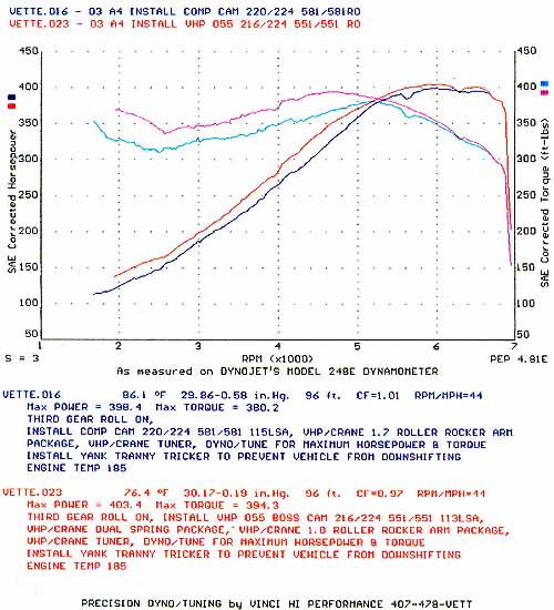
here, let me bring this to the table. here's adyno that vinci has done using the 03 corvette AFR test vehicle. it pits a comp cam 220/224 .581/.581 115LSA with the 1.7 accelerated lift rockers vs the vinci 056 cam 216/224 .551/.551 (1.7) 113 LSA with the 1.8 accelerated lift rockers (total lift is .583/.583). looks like it works to me. smaller duration more rocker and you get this:
Originally Posted by Rokko
Fantastic discussion guys.
Doesn't the quick lift rocker revert to advertised ratio after ~.300 lift as it rolls over the nose and then back to 1.8 or whatever the spec is as it rolls to the the backside @ ~.300 lift.
Doesn't the quick lift rocker revert to advertised ratio after ~.300 lift as it rolls over the nose and then back to 1.8 or whatever the spec is as it rolls to the the backside @ ~.300 lift.

Originally Posted by mrr23
here, let me bring this to the table. here's adyno that vinci has done using the 03 corvette AFR test vehicle. it pits a comp cam 220/224 .581/.581 115LSA with the 1.7 accelerated lift rockers vs the vinci 056 cam 216/224 .551/.551 (1.7) 113 LSA with the 1.8 accelerated lift rockers (total lift is .583/.583). looks like it works to me. smaller duration more rocker and you get this:
Yep that's what happens in that case.... Change that over to a standard rocker (1.8:1 Constant Ratio), change the cam to add a tad more overlap to make the overlap the quick lift rockers give you and you would have the exact same result, and probabaly more TQ due to the later EVO point.
It looks like a crutch to me... Basically it adds duration below .200 to the cam. You could do the same thing with different lobes. I know how it works it's geometry... That's all.... as I said it's the same thing as putting a shorter pushrod in the motor. All you are doing is changing what part of the arc the rocker arm is starting on... not that hard to figure out.
Hell that test is not a really good apples to apples test if you know cams... So a cam with more duration, less overlap, bad IVC points for the RPM range of the cam and horrible DCR is getting beat out by a cam that's better in all these aspects PLUS it has these trick rockers on it? OH YEAH THAT MUST BE THE ROCKERS.... Bad example. Breaks all rules of the scientific method, and any engine builder worth their salt would test the same cam, with different rockers with the same net ratio against one another to test this theory.
Hell you could take more exhaust duration out of that cam, even up the intake and exhaust to a single pattern or close to it and then put the LSA where it belongs and get better results.... Same thing that Jay Allen, Ed Curtis and I do all the time, except we don't fool around with rockers to get it there.
Believe me if you put these rockers on a cam that is designed correctly you are not going to see any added benefit.
Read this....
Originally Posted by SStrokerAce
BTW I just looked at a cam I'm doing for a motor now.... Hyd Roller over .600 lift (.630 range) medium sized duration, sub 7500rpm and a "street motor"
.000-.100 68 degs 22%
.100-.200 40 degs 13%
.200-.300 26 degs 8.5%
.300-.400 34 degs 11%
.400-.500 32 degs 10.5%
.500-.600 60 degs 20%
.600 + 44 degs 14.5%
Now making a change in that motors flow curve from .200-.400" lift of 4.4% nets less than a 1% loss in max power and about .4% in average power. Now if you changed the flow at the top end .600+ 4.4% you would see a 1% loss in average power. This is with big changes in flow of 15-20cfm at the top end. That's 150% more loss in average power.
To add a little more to this the lowest pressures seen in the port (highest vacuum) at the max VE occur between .420-.520" lobe lift (opening) and the highest pressures occur between .150-.020" lift (closing), from lowest vacuum to highest pressure there is roughly a 15psi change in pressures. The highest average velocities occured for 84 degs at lifts over .500". The more flow you have in that lift area will raise the amount of duration that the motor pulls that high of a velocity given the same sized port.
So you can see the time when the port is filling the motor the fastest is around max lift, and the time it's filling it with the most pressure is around valve closing while the piston is coming up the bore.
Again this is what I do, build motors and optimize valvetrains... I understand what the rockers are for and for most guys they will show results because of the standard mistakes most off the shelf cams have, it fixes. Some cams it wouldn't help at all, but small cams with a wide LSA these rockers will love. Hell they will kick *** on a stock cammed motor.
And yes I do understand you do own them and in that case they work out well. You could do it another way better IMHO.
One thing these would be good for is a car that had to pass emissions. With a cam that was marginable on stock rockers this would definately help the performance but would hurt the emissions testing.
Bret
now, why do you call it a crutch??? i guess you didn't read the part where mark campbell said, there are no constant ratio rockers. the only constant ratio rocker would be a 1:1 ratio. then both arcs are the same. oh, and that comp cam is one of AFR's designed cams. they provided it for the test. my viewpoint of using higher ratio rockers is so you slow down the lifter. that way, there's less chance of lofting it too much off the cam itself. i would be willing to bet that most valve float issues are because of the super aggressive ramps on the cam itself. by doing it from the cam, the spring has to control alot more parts than just the valve. it has to control the speed of the lifter also. the motor only cares about what happens at the valve doesn't it??
not a bad example at all. the purpose of the test was to show that you can do the same or better with smaller duration cams and larger ratio rockers. GM has been moving in that direction for the last 10+ years. most recently with the move up to 1.8 in the LS7 motors. something has to be going right. i'll find my post where i was comparing GMs move from 1.5 to 1.8 over the years. overall, the cams durations only changed slightly. but, they moved ratios dramatically.
any actual tests you have handy showing this to be the case?? not being an *** (although others will say differently  ). you threw it out there to be asked.
Originally Posted by SStrokerAce
Hell that test is not a really good apples to apples test if you know cams... So a cam with more duration, less overlap, bad IVC points for the RPM range of the cam and horrible DCR is getting beat out by a cam that's better in all these aspects PLUS it has these trick rockers on it? OH YEAH THAT MUST BE THE ROCKERS.... Bad example. Breaks all rules of the scientific method, and any engine builder worth their salt would test the same cam, with different rockers with the same net ratio against one another to test this theory.
Originally Posted by SStrokerAce
Yep that's what happens in that case.... Change that over to a standard rocker (1.8:1 Constant Ratio), change the cam to add a tad more overlap to make the overlap the quick lift rockers give you and you would have the exact same result, and probabaly more TQ due to the later EVO point.
). you threw it out there to be asked. Last edited by mrr23; May 17, 2005 at 09:07 PM.
ok here's some cam food for thought. over the years, GM has played with duration to get more power. now, of course these are different versions of the SBC motors (Gen I, II, and III)
year/motor -- duration -- cam lobe lift -- rocker ratio -- valve lift
87 350 TPI -- 202/207 -- .269/.276 -------- 1.5 ------ .404/.415
96 350 LT1 -- 205/207 -- .298/.306 -------- 1.5 ------ .447/.459
96 350 LT4 -- 203/210 -- .297/.299 -------- 1.6 ------ .476/.479
01 346 LS1 -- 197/207 -- .274/.281 -------- 1.7 ------ .467/.479
01 346 LS6 -- 207/217 -- .308/.308 -------- 1.7 ------ .525/.525
05 427 LS7 -- 211/230 -- .328/.328 -------- 1.8 ------ .591/.591
in the LT1 vs LT4 you see that GM made a minor change in duration and larger on the rockers.
now, on the LS1 vs LS6 they went the more aggressive ramps route.
and with the LS7, they went both (well they went bigger everything). so, more agressive ramps and larger ratios work just fine. but how much more agressive on the ramps is the only question people have.
Originally Posted by mrr23
now, why do you call it a crutch??? i guess you didn't read the part where mark campbell said, there are no constant ratio rockers. the only constant ratio rocker would be a 1:1 ratio. then both arcs are the same. oh, and that comp cam is one of AFR's designed cams. they provided it for the test.
Yeah, the Comp designed cam is sketchy at best... I don't use them to spec my cams, just design the lobes, grind them and then check them. Works out well that way. They do an exceptional job at lobe design IMHO.
Originally Posted by mrr23
my viewpoint of using higher ratio rockers is so you slow down the lifter. that way, there's less chance of lofting it too much off the cam itself. i would be willing to bet that most valve float issues are because of the super aggressive ramps on the cam itself. by doing it from the cam, the spring has to control alot more parts than just the valve. it has to control the speed of the lifter also. the motor only cares about what happens at the valve doesn't it??
Valve float happens because of a few things.
1. not enough spring pressure
2. too much valvetrain mass
3. too aggressive cam lobes
4. too much RPM for the combination
BTW the higher rocker ratio is one way to go but it also loads the pushrod and lifter much more, a rocker multiplies lobe movements to the valve AND multiplies spring loads back the other way. Gotts to think about BOTH sides and how they change what's going on.
Originally Posted by mrr23
not a bad example at all. the purpose of the test was to show that you can do the same or better with smaller duration cams and larger ratio rockers. GM has been moving in that direction for the last 10+ years. most recently with the move up to 1.8 in the LS7 motors. something has to be going right. i'll find my post where i was comparing GMs move from 1.5 to 1.8 over the years. overall, the cams durations only changed slightly. but, they moved ratios dramatically.
ok here's some cam food for thought. over the years, GM has played with duration to get more power. now, of course these are different versions of the SBC motors (Gen I, II, and III)
year/motor -- duration -- cam lobe lift -- rocker ratio -- valve lift
87 350 TPI -- 202/207 -- .269/.276 -------- 1.5 ------ .404/.415
96 350 LT1 -- 205/207 -- .298/.306 -------- 1.5 ------ .447/.459
96 350 LT4 -- 203/210 -- .297/.299 -------- 1.6 ------ .476/.479
01 346 LS1 -- 197/207 -- .274/.281 -------- 1.7 ------ .467/.479
01 346 LS6 -- 207/217 -- .308/.308 -------- 1.7 ------ .525/.525
05 427 LS7 -- 211/230 -- .328/.328 -------- 1.8 ------ .591/.591
in the LT1 vs LT4 you see that GM made a minor change in duration and larger on the rockers.
now, on the LS1 vs LS6 they went the more aggressive ramps route.
and with the LS7, they went both (well they went bigger everything). so, more agressive ramps and larger ratios work just fine. but how much more agressive on the ramps is the only question people have.
Notice my 4 points up above? They apply to OEMs more than you think
From the LT1 to the LT4 they dropped the valve mass dramatically, and increased the spring pressure.
The LS1, got the addition of a beehive spring to reduce effective valve mass, and a 55mm cam journal to make the lobes contain a lot of area and have less forces on the valvetrain in terms of what is happening on the lifter end of the scale... Plus you have a much stiffer cam and tons of room to grow. Basically fixing a 50 year old design.
The LS6 did the same thing as the LT4 did.
Notice to this point the max lobe lift is about the same still???
The LS7 did all of it all over again.... Ti valves, Ti Pushrods, more Rocker Ratio etc... It's not cheap at all man. I have a set of Ti valves sitting here in front of me and at $80 a valve, you think twice about if you need them or not. The LS7 design had no other way to do it, the lengths and physical size of the valves and the durability cycle they had to go thru dictated that they make them of Ti. The ones in front of me are very similar in length and size to the LS7 valves and they are still 90g's, about what a hollow stem LS6 or LT4 valve is.
The 02 LS6 cam and the 05/6 LS7 cam have taken the biggest jump in lobe lift. My guess is that they are finding better spring materials to use.. I don't know because I don't use stock OEM spring but that would be my bet.
Originally Posted by mrr23
any actual tests you have handy showing this to be the case?? not being an *** (although others will say differently ). you threw it out there to be asked.
). you threw it out there to be asked.MNR-0: Anyone running a 110-111LSA baby cam? Something in the order of 212-216?
EDC: 93Pony and I use these kind of grinds...
It all depends on the "combination"...
Ed
Referenced from this thread....
Honestly most custom cams on EFI cars are so far from what people normally use it's scary... IMHO there are some awesom shelf cams like Futrals F13, that is a kick *** shelf cam for guy who really wants to twist and race his car.
Bret
Last edited by SStrokerAce; May 17, 2005 at 10:53 PM.
Originally Posted by SStrokerAce
BTW the higher rocker ratio is one way to go but it also loads the pushrod and lifter much more, a rocker multiplies lobe movements to the valve AND multiplies spring loads back the other way. Gotts to think about BOTH sides and how they change what's going on.
This "beneficial low-lift enhancement" can always be put on the lobe, right? So why didn't cam lobe creators do that? Is there something that I'm missing about system inertia in one case vs. the other?
Why not make a lobe that does this with stock (free) rockers?
Well basically it's making a longer easier ramp to replicate this effect... You can do that with some of the Comp lobes and from what I have seen Cam Motions (who do Futrals cams) are usually like this as well.... It's very good to control the valve this way.
If you want to run aggressive stuff with large ratio rockers you need to work on getting the mass of the valvetrain down so you can run less spring pressure.
BTW I don't think these rockers are bad, they just have certain designs that they will work better in than others. They would be cool for someone who needs to pass a sniffer test, design the cam around using them AND passing emissions with the stock rocker arms. Swap the stockers on to cut down overlap, swap the Cranes on when you are done.
Bret