

Would Yella Terra Be Worth It.


Launching!
Joined: Apr 2005
Posts: 208
Likes: 0
From: CAIRNS QLD AUST
First is set the wipe pattern up correctly, then measure for pushrod length. If shims are required to get the correct wipe, then the pushrod length may change and should be measured. Here is how I did mine (copied from my post on Corvetteforum).
---------------------------------------------------------------------
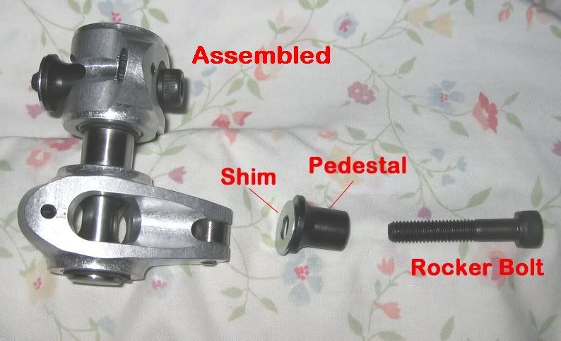
I just finished setting up the wipe pattern of my Yella Terra roller rockers on my new AFR heads. The Yella Terra rockers are fixed fulcrum rockers (as opposed to a fully adjustable rocker like the Crane I set up on my current configuration) and are furnished with a rocker pedestal and a single shim that is 0.048� thick, which when placed under the pedestal, will raise the fulcrum of the rocker and move the roller location towards the exhaust side of the valve stem. The goal is to center the wipe pattern on the valve stem and minimize the width of the pattern. When the width is reduced over the course of rocker motion, then the side loading into the valve guides is also reduced. This not only provides faster valve motions but also minimizes valve guide wear. Below is a photo of how the Yella Terra setup is installed with the pedestal and shim (if used) under the rocker shaft and the bolt passing through the assembly and into the threaded hole in the head.

I am doing this on the workbench but this can also be done on the car. The workbench has the advantage that there is more time to set things up and if parts are needed the car won�t be down as it would if you were in the middle of the head installation. Plus, it�s easier on the back.
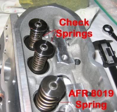
The first step is to remove two valve springs and replace them with checking springs. I have two sets of checking springs and I used the stiffer set since they provide more force against the rocker to help in wiping off the ink that is applied to obtain the final wipe pattern.

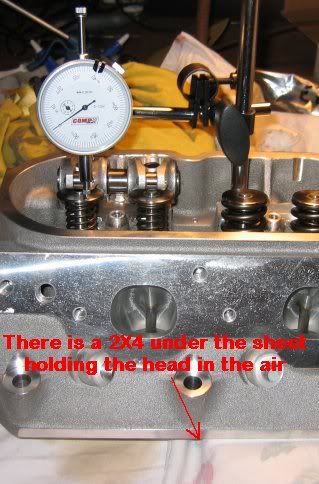
Once the check springs are installed, set the cylinder head in the air such that the valves can be manually operated without contacting the workbench surface. Using a dial indicator allows you to manually operate the rocker arm to the required valve lift. Since the final wipe pattern is lift sensitive, you have to ensure that the motion you are moving the rocker through imitates that which will be driven by the cam.
The next step in the operation is to setup your rockers and snug the bolts. There is no need to fully torque the bolts and load the threads in the aluminum head. Hand snug is fine and will eliminate thread wear as the bolts are taken in and out several times during the process. Once the rockers are in place with the shims that are being checked, and your measurement method is setup to determine how much the valve is being moved, use a Sharpie to spread black ink on the upper surface of the valve stem. I have found it best to not allow the ink to dry too long as with checking springs it doesn�t wipe off as well. Instead, I use a cotton swap and pull off most of the cotton then soak it with ink from the Sharpie. Then I simply rotate the rocker back off of the valve stem and apply the ink. After it is just dry, then the wipe test is conducted by rotating the rocker arm by hand in the same manner as the pushrod and cam would if the head were on the motor. This process is repeated until a satisfactory wipe pattern is found by adjusting the height of the shim. A thicker shim should push the wipe pattern towards the exhaust side of the valve stem. This will be critical later as the pushrod length changes approximately 0.016� in length for every 0.010� of shim you add to the rocker pedestal so that the wipe pattern needs to be established first followed by the pushrod length.

I started the process with no shim in place under the pedestal and then added shims until I got the desired wipe pattern. Washers can be used and stacked for this process but once a thickness is found you need to find a single piece shim of the correct thickness. In the photo below (sorry for the crappy photography), three of the patterns are shown. On the left is the wipe pattern without a shim. Notice that the wipe pattern is towards the intake side of the valve stem and barely gets to the valve stem center over the course of travel of the roller on the rocker. In the middle photo, shimming has now moved the wipe pattern towards the center of the valve stem. It is still biased to the intake side and a little wide. The final wipe pattern on the right is the shim setup I will use for final installation, as I am very pleased with the final wipe pattern obtained. Note that the shim value can be different for any given setup, the point being that simply bolting on the rockers from the box would have yielded the pattern on the left and likely resulted in not only disappointing results but higher than necessary valve guide wear for my installation. I bought my final shims (11/32" ID, 13/16" OD from McMaster-Carr, which are available in a lot of thicknesses. These were pretty much a perfect fit under the pedestal if you need a thickness that differs than the one provided by Yella Terra for any reason.

---------------------------------------------------------------------
I just finished setting up the wipe pattern of my Yella Terra roller rockers on my new AFR heads. The Yella Terra rockers are fixed fulcrum rockers (as opposed to a fully adjustable rocker like the Crane I set up on my current configuration) and are furnished with a rocker pedestal and a single shim that is 0.048� thick, which when placed under the pedestal, will raise the fulcrum of the rocker and move the roller location towards the exhaust side of the valve stem. The goal is to center the wipe pattern on the valve stem and minimize the width of the pattern. When the width is reduced over the course of rocker motion, then the side loading into the valve guides is also reduced. This not only provides faster valve motions but also minimizes valve guide wear. Below is a photo of how the Yella Terra setup is installed with the pedestal and shim (if used) under the rocker shaft and the bolt passing through the assembly and into the threaded hole in the head.
I am doing this on the workbench but this can also be done on the car. The workbench has the advantage that there is more time to set things up and if parts are needed the car won�t be down as it would if you were in the middle of the head installation. Plus, it�s easier on the back.
The first step is to remove two valve springs and replace them with checking springs. I have two sets of checking springs and I used the stiffer set since they provide more force against the rocker to help in wiping off the ink that is applied to obtain the final wipe pattern.
Once the check springs are installed, set the cylinder head in the air such that the valves can be manually operated without contacting the workbench surface. Using a dial indicator allows you to manually operate the rocker arm to the required valve lift. Since the final wipe pattern is lift sensitive, you have to ensure that the motion you are moving the rocker through imitates that which will be driven by the cam.
The next step in the operation is to setup your rockers and snug the bolts. There is no need to fully torque the bolts and load the threads in the aluminum head. Hand snug is fine and will eliminate thread wear as the bolts are taken in and out several times during the process. Once the rockers are in place with the shims that are being checked, and your measurement method is setup to determine how much the valve is being moved, use a Sharpie to spread black ink on the upper surface of the valve stem. I have found it best to not allow the ink to dry too long as with checking springs it doesn�t wipe off as well. Instead, I use a cotton swap and pull off most of the cotton then soak it with ink from the Sharpie. Then I simply rotate the rocker back off of the valve stem and apply the ink. After it is just dry, then the wipe test is conducted by rotating the rocker arm by hand in the same manner as the pushrod and cam would if the head were on the motor. This process is repeated until a satisfactory wipe pattern is found by adjusting the height of the shim. A thicker shim should push the wipe pattern towards the exhaust side of the valve stem. This will be critical later as the pushrod length changes approximately 0.016� in length for every 0.010� of shim you add to the rocker pedestal so that the wipe pattern needs to be established first followed by the pushrod length.
I started the process with no shim in place under the pedestal and then added shims until I got the desired wipe pattern. Washers can be used and stacked for this process but once a thickness is found you need to find a single piece shim of the correct thickness. In the photo below (sorry for the crappy photography), three of the patterns are shown. On the left is the wipe pattern without a shim. Notice that the wipe pattern is towards the intake side of the valve stem and barely gets to the valve stem center over the course of travel of the roller on the rocker. In the middle photo, shimming has now moved the wipe pattern towards the center of the valve stem. It is still biased to the intake side and a little wide. The final wipe pattern on the right is the shim setup I will use for final installation, as I am very pleased with the final wipe pattern obtained. Note that the shim value can be different for any given setup, the point being that simply bolting on the rockers from the box would have yielded the pattern on the left and likely resulted in not only disappointing results but higher than necessary valve guide wear for my installation. I bought my final shims (11/32" ID, 13/16" OD from McMaster-Carr, which are available in a lot of thicknesses. These were pretty much a perfect fit under the pedestal if you need a thickness that differs than the one provided by Yella Terra for any reason.
any chance of emailing the pic of of your setup above as they seam to be gone
i am just in the process of wanting to do mine with the YT6667 rockers
and mast 11deg heads
it would be appreciated
my EMAIL IS
bob@restlessenterprises.com.au
cheers


Taken from http://forums.corvetteforum.com/c5-t...e-pattern.html
where this thread still lives and is badass......
I have had several people e-mail and ask how to do this so I thought I would post this for discussion and information. I just finished setting up the wipe pattern of my Yella Terra roller rockers on my new AFR heads. The Yella Terra rockers are fixed fulcrum rockers (as opposed to a fully adjustable rocker like the Crane I set up on my current configuration) and are furnished with a rocker pedestal and a single shim that is 0.048” thick, which when placed under the pedestal, will raise the fulcrum of the rocker and move the roller location towards the exhaust side of the valve stem. The goal is to center the wipe pattern on the valve stem and minimize the width of the pattern. When the width is reduced over the course of rocker motion, then the side loading into the valve guides is also reduced. This not only provides faster valve motions but also minimizes valve guide wear. Below is a photo of how the Yella Terra setup is installed with the pedestal and shim (if used) under the rocker shaft and the bolt passing through the assembly and into the threaded hole in the head.
I am doing this on the workbench but this can also be done on the car. The workbench has the advantage that there is more time to set things up and if parts are needed the car won’t be down as it would if you were in the middle of the head installation. Plus, it’s easier on the back.
The first step is to remove two valve springs and replace them with checking springs. I have two sets of checking springs and I used the stiffer set since they provide more force against the rocker to help in wiping off the ink that is applied to obtain the final wipe pattern.
Once the check springs are installed, set the cylinder head in the air such that the valves can be manually operated without contacting the workbench surface. Using a dial indicator allows you to manually operate the rocker arm to the required valve lift. Since the final wipe pattern is lift sensitive, you have to ensure that the motion you are moving the rocker through imitates that which will be driven by the cam.
The next step in the operation is to setup your rockers and snug the bolts. There is no need to fully torque the bolts and load the threads in the aluminum head. Hand snug is fine and will eliminate thread wear as the bolts are taken in and out several times during the process. Once the rockers are in place with the shims that are being checked, and your measurement method is setup to determine how much the valve is being moved, use a Sharpie to spread black ink on the upper surface of the valve stem. I have found it best to not allow the ink to dry too long as with checking springs it doesn’t wipe off as well. Instead, I use a cotton swap and pull off most of the cotton then soak it with ink from the Sharpie. Then I simply rotate the rocker back off of the valve stem and apply the ink. After it is just dry, then the wipe test is conducted by rotating the rocker arm by hand in the same manner as the pushrod and cam would if the head were on the motor. This process is repeated until a satisfactory wipe pattern is found by adjusting the height of the shim. A thicker shim should push the wipe pattern towards the exhaust side of the valve stem. This will be critical later as the pushrod length changes approximately 0.016” in length for every 0.010” of shim you add to the rocker pedestal so that the wipe pattern needs to be established first followed by the pushrod length.
I started the process with no shim in place under the pedestal and then added shims until I got the desired wipe pattern. Washers can be used and stacked for this process but once a thickness is found you need to find a single piece shim of the correct thickness. In the photo below (sorry for the crappy photography), three of the patterns are shown. On the left is the wipe pattern without a shim. Notice that the wipe pattern is towards the intake side of the valve stem and barely gets to the valve stem center over the course of travel of the roller on the rocker. In the middle photo, shimming has now moved the wipe pattern towards the center of the valve stem. It is still biased to the intake side and a little wide. The final wipe pattern on the right is the shim setup I will use for final installation, as I am very pleased with the final wipe pattern obtained. Note that the shim value can be different for any given setup, the point being that simply bolting on the rockers from the box would have yielded the pattern on the left and likely resulted in not only disappointing results but higher than necessary valve guide wear for my installation. I bought my final shims (11/32" ID, 13/16" OD from McMaster-Carr, which are available in a lot of thicknesses. These were pretty much a perfect fit under the pedestal if you need a thickness that differs than the one provided by Yella Terra for any reason.
 This image has been resized. Click this bar to view the full image. The original image is sized 862x282 and weights 46KB.
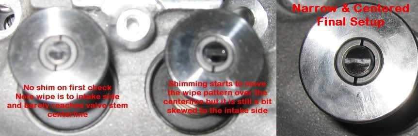
where this thread still lives and is badass......
I have had several people e-mail and ask how to do this so I thought I would post this for discussion and information. I just finished setting up the wipe pattern of my Yella Terra roller rockers on my new AFR heads. The Yella Terra rockers are fixed fulcrum rockers (as opposed to a fully adjustable rocker like the Crane I set up on my current configuration) and are furnished with a rocker pedestal and a single shim that is 0.048” thick, which when placed under the pedestal, will raise the fulcrum of the rocker and move the roller location towards the exhaust side of the valve stem. The goal is to center the wipe pattern on the valve stem and minimize the width of the pattern. When the width is reduced over the course of rocker motion, then the side loading into the valve guides is also reduced. This not only provides faster valve motions but also minimizes valve guide wear. Below is a photo of how the Yella Terra setup is installed with the pedestal and shim (if used) under the rocker shaft and the bolt passing through the assembly and into the threaded hole in the head.
I am doing this on the workbench but this can also be done on the car. The workbench has the advantage that there is more time to set things up and if parts are needed the car won’t be down as it would if you were in the middle of the head installation. Plus, it’s easier on the back.
The first step is to remove two valve springs and replace them with checking springs. I have two sets of checking springs and I used the stiffer set since they provide more force against the rocker to help in wiping off the ink that is applied to obtain the final wipe pattern.
Once the check springs are installed, set the cylinder head in the air such that the valves can be manually operated without contacting the workbench surface. Using a dial indicator allows you to manually operate the rocker arm to the required valve lift. Since the final wipe pattern is lift sensitive, you have to ensure that the motion you are moving the rocker through imitates that which will be driven by the cam.
The next step in the operation is to setup your rockers and snug the bolts. There is no need to fully torque the bolts and load the threads in the aluminum head. Hand snug is fine and will eliminate thread wear as the bolts are taken in and out several times during the process. Once the rockers are in place with the shims that are being checked, and your measurement method is setup to determine how much the valve is being moved, use a Sharpie to spread black ink on the upper surface of the valve stem. I have found it best to not allow the ink to dry too long as with checking springs it doesn’t wipe off as well. Instead, I use a cotton swap and pull off most of the cotton then soak it with ink from the Sharpie. Then I simply rotate the rocker back off of the valve stem and apply the ink. After it is just dry, then the wipe test is conducted by rotating the rocker arm by hand in the same manner as the pushrod and cam would if the head were on the motor. This process is repeated until a satisfactory wipe pattern is found by adjusting the height of the shim. A thicker shim should push the wipe pattern towards the exhaust side of the valve stem. This will be critical later as the pushrod length changes approximately 0.016” in length for every 0.010” of shim you add to the rocker pedestal so that the wipe pattern needs to be established first followed by the pushrod length.
I started the process with no shim in place under the pedestal and then added shims until I got the desired wipe pattern. Washers can be used and stacked for this process but once a thickness is found you need to find a single piece shim of the correct thickness. In the photo below (sorry for the crappy photography), three of the patterns are shown. On the left is the wipe pattern without a shim. Notice that the wipe pattern is towards the intake side of the valve stem and barely gets to the valve stem center over the course of travel of the roller on the rocker. In the middle photo, shimming has now moved the wipe pattern towards the center of the valve stem. It is still biased to the intake side and a little wide. The final wipe pattern on the right is the shim setup I will use for final installation, as I am very pleased with the final wipe pattern obtained. Note that the shim value can be different for any given setup, the point being that simply bolting on the rockers from the box would have yielded the pattern on the left and likely resulted in not only disappointing results but higher than necessary valve guide wear for my installation. I bought my final shims (11/32" ID, 13/16" OD from McMaster-Carr, which are available in a lot of thicknesses. These were pretty much a perfect fit under the pedestal if you need a thickness that differs than the one provided by Yella Terra for any reason.
This image has been resized. Click this bar to view the full image. The original image is sized 862x282 and weights 46KB.


