When you click on links to various merchants on this site and make a purchase, this can result in this site earning a commission. Affiliate programs and affiliations include, but are not limited to, the eBay Partner Network.
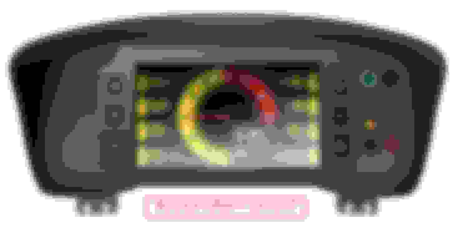
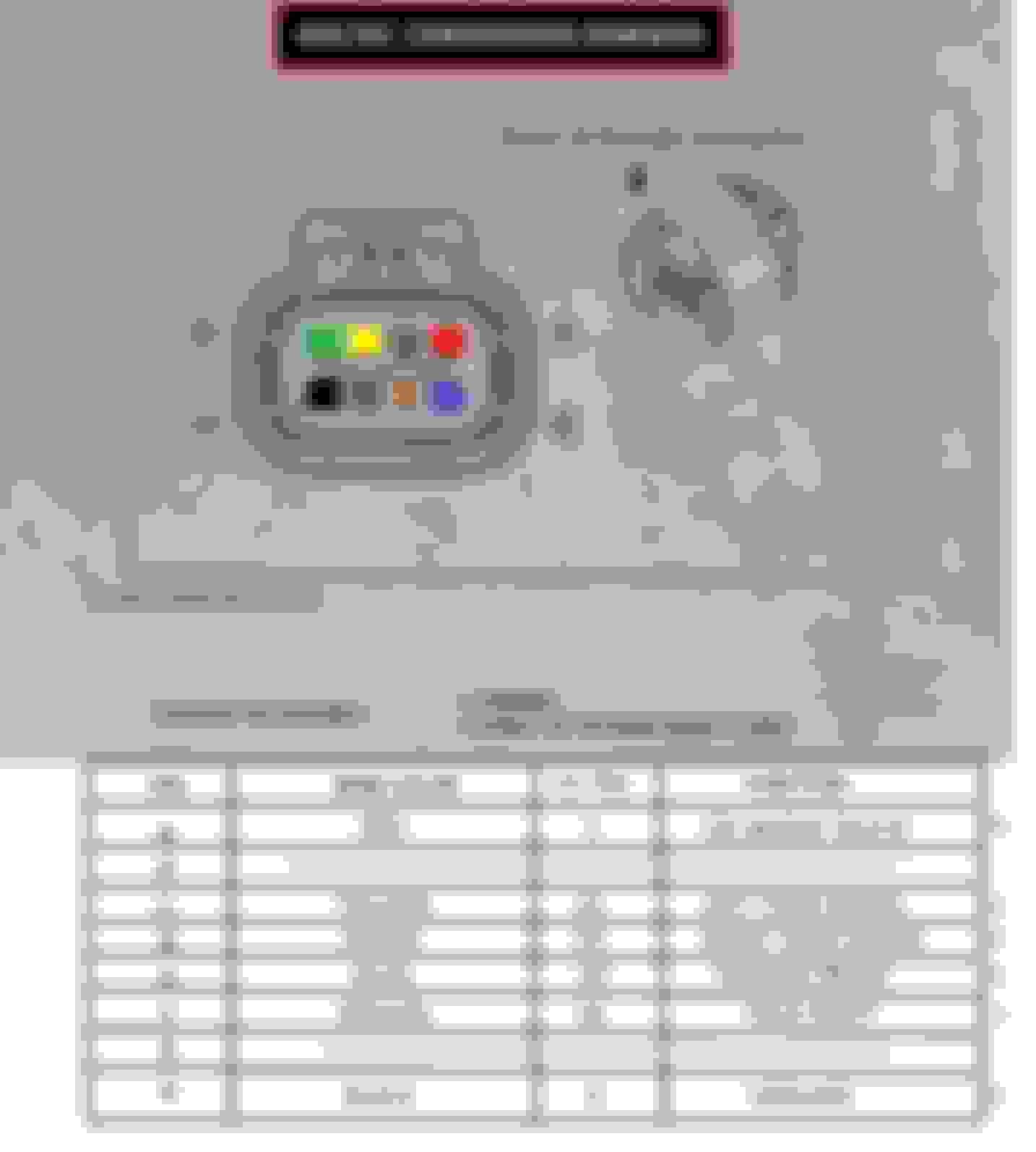
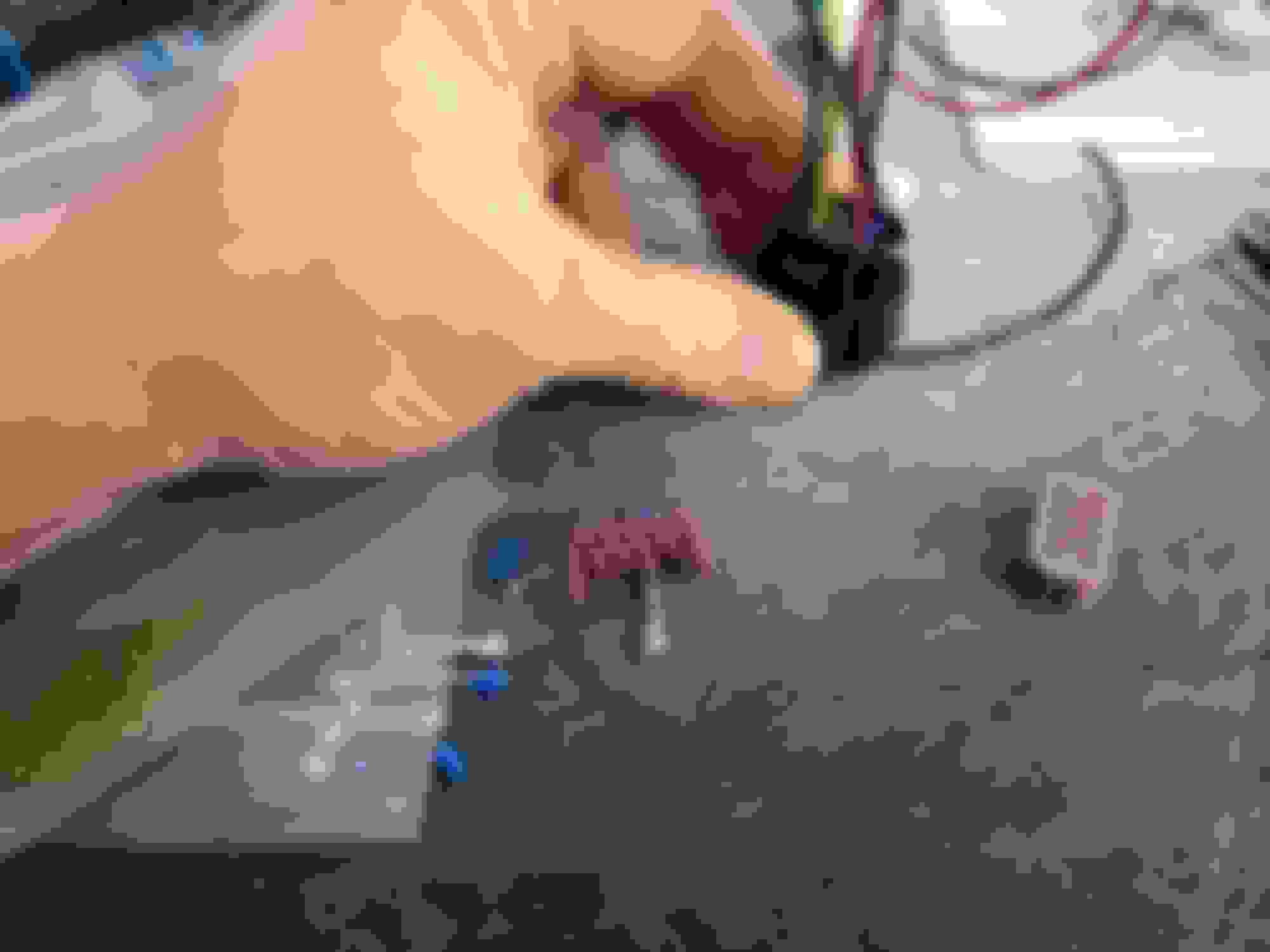
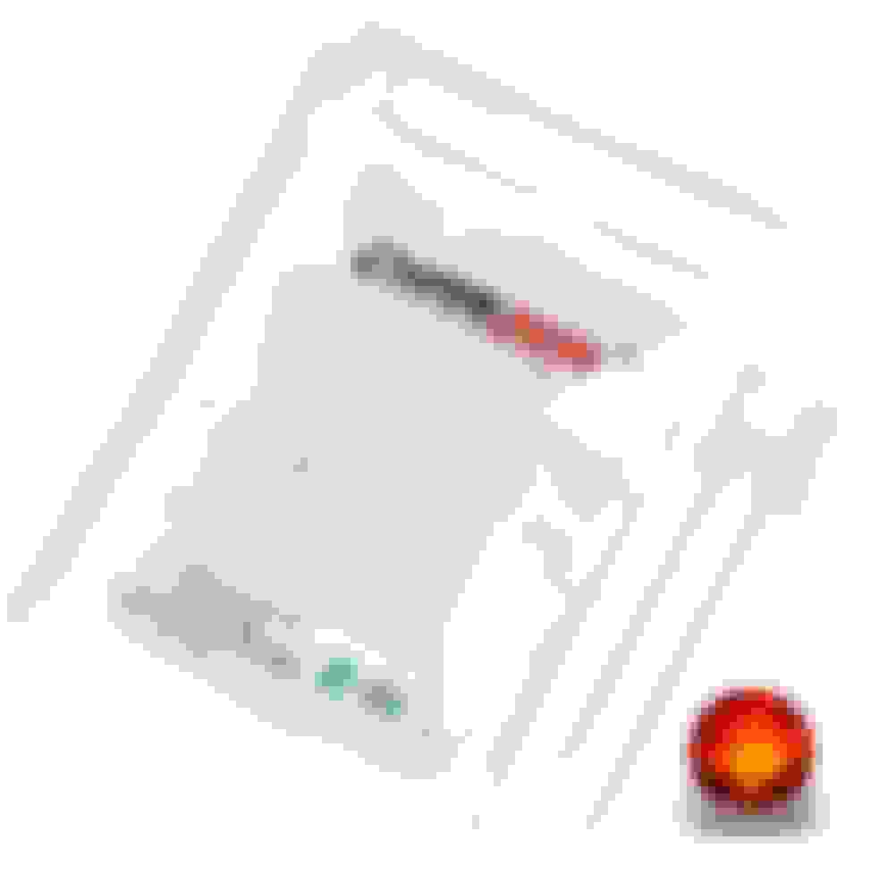
Taking apart the cluster to the bare circuit board. De-soldering these LED's. The DRL, High Beam, CEL, ABS, Air Bag and Low Voltage. I wish this was easier, but GM likes to keep dash lights ran through the low speed Serial Bus and the only way I can get these to show is this exact way. So I plan to take just the circuit board out of the cluster. I'm running 22 awg wires from the dash light solder pins into 5mm flat top 2v LED's into the new cluster housing with icon based light housings. The Cluster Circuit board will be covered in Polyimide Tape and Solder mask my jumper wires and tucked behind the new cluster. Since I run a E40 Gen 4 PCM it uses High Speed Can so I can run Speed, RPM, Fuel Level, and everything else directly from the Can Bus. I'm also making this easily installable/removal by using GT150 8 pin & 12 pin weather pack connectors. Can't forget you have to make your own diagrams for the future just incase lol... I have the rest of the pieces to the project are coming, but figured I could make a post... I know the IC-7 has a CEL but wanted to run it with the other LED's for ME state Inspection. They need to see the lights cycle to make sure its operational.

 05-06-2024, 02:38 PM