When you click on links to various merchants on this site and make a purchase, this can result in this site earning a commission. Affiliate programs and affiliations include, but are not limited to, the eBay Partner Network.
Hi All,
Some of you will have no doubt read my experience's with road racing standard componentary LS7 engines, and the issue's we experienced and largely solved.
I recently purchased a 2009 Mosler MT900R-GT3 with a near standard LS7 engine because I was by now familiar with the engine and was confident that we could increase the Horsepower significantly however, the comparatively long stroke, limits the RPM potential, which is something that we felt would help us to achieve close to 800 BHP if we could comfortably rev the engine to 8,200 RPM, this would also enable us to keep torque under 550ftlb's, which is highly desirable if you want the driveline to survive in endurance racing.
After months of research we decided on a bore of 4.185" with a 3.625" stroke and using a 6.200" rod length. After considering all the options we decided to use a Gen4 aluminum Ls Truck block, which is reputed to be the stiffest strongest LS engine block available.
We considered the Superdeck, however as a mechanical engineer I was concerned about the potential for weld distortion, we also liked the additional thermal stability that a wet liner offered, so settled on Darton's MID system, which led us to the co-developer of the MID patent, Steve Demirjian of Racing Engine Developments [RED] as we figured he would have more experience than anybody with the installation of the sleeves etc.
After having to wait until after Christmas for Darton to finish the sleeve's Steve was as good as his word and as the accompanying photo's show, completed the Block in under two week's.
Steve also shared his years of experience with us, and we gladly took his advice on how best to deal with thermal growth, crankcase breathing issues etc.
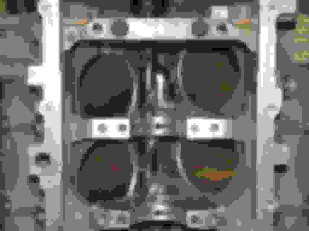
The first operation on a brand new block was drilling the crankcase breathers.<br/>
New crankcase breather holes completed.
Last edited by KiwiKid; Jan 23, 2015 at 03:24 AM.
Reason: grammar
very cool build...@ 136 crank revolutions per second you just got rid of 68 linear feet of ring travel per second by knocking the stroke from 4" to 3.625"
awesome to see the block transformation.....
Cool build! I'm not positive of it, but it seems to me from now owning an LS6, an ERL Superdeck, and an LS7, that the MID sleeve does the best job of cooling of the 3.
Also, I'm in to see the results! You rarely see big bore MID LS motors!
very cool build...@ 136 crank revolutions per second you just got rid of 68 linear feet of ring travel per second by knocking the stroke from 4" to 3.625"
awesome to see the block transformation.....
Thanks AR. you are right on the money, we also went with the longer 6.200" long connecting-rod to reduce side loading on the piston.
Most people on this forum have probably never heard of Marine Crank out in CA, as Dave does mostly Porsche and BMW billet crank's, and Like Steve at RED, Dave is pretty much a one man-band, but his billet crank's are truly awesome pieces. It also helps that he hails from the "Land Of The Long White Cloud" [New Zealand]
Through Dave I ended up at Pauter also out in CA, and another Euro engine specialist, after talking to these good old boy's, we decided to use their unique cross section, connecting-rod as in our opinion it has both strength and windage advantages over both conventional H-beam and I beam connecting rod's. Take a look at their website if you are interested, http://pauter.com/parts/rods/
We are using a typical Nascar style little-end running the ultra stiff C-350/DHL coated 0.827" wrist-pin's directly in the little-end with out any bushing and pressure oil feed through an .080" EDM'd [riffle bored] hole through the centre of the rod, and directing oil on up to the underneath of the piston crown. The flat-top piston's themselves are Diamond's custom billet typical Nascar style 9 pocket design, to suit our 12.8 to 1 desired compression ratio.
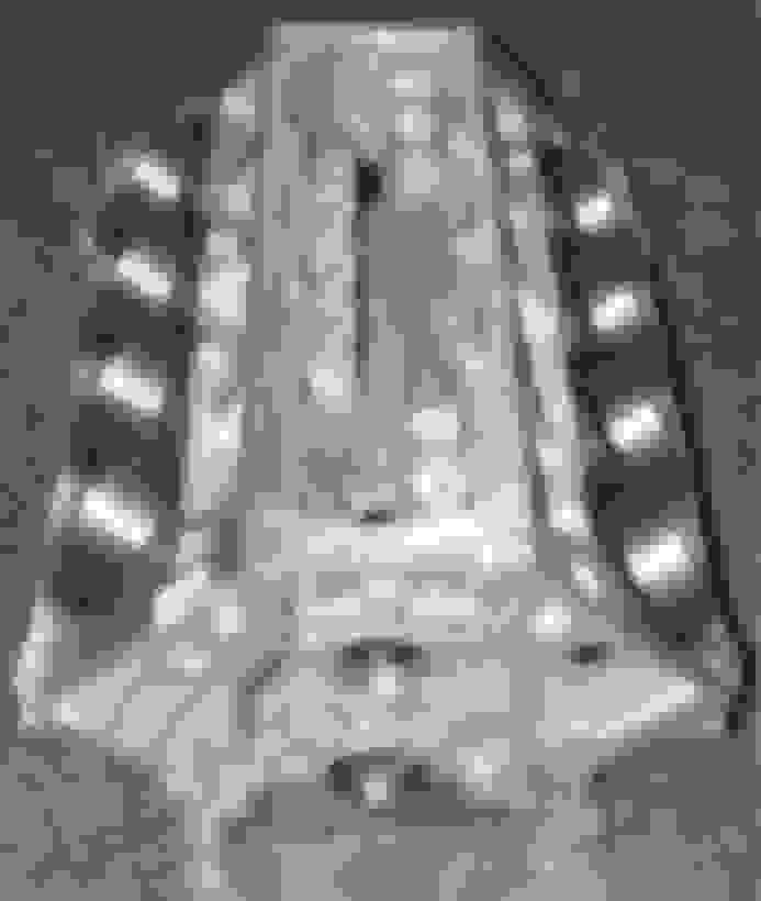
I have include one more photo of the block prep as it shows just how much material is machined out of each cylinder bank, scary stuff if you dont know what you are doing.
This photo shows the massive amount of material removed from each cylinder bank.
Excellent information. The sleeves look like they are in effect siamesed where they meet up. That would be good for extra wall strength in that area.
Hi GT,
You are right they are in effect "Siamesed" as the flat surface area on the side 's of each individual sleeve, which extend's vertically from the top of the sleeve almost to the bottom, are sandwiched together in the installation thus forming 3 relatively thick vertical beam's of centrifugally cast ductile iron.
Once up to operating temperature the bank of sleeves are held in tension forming in effect a solid nodular iron bridge like structure which reinforces the block's upper deck.
I think most performance engine builders believe that centrifugally cast nodular iron sleeves provide a very tough ideal sealing surface, which is worth horspower, and our engine builder is of the same mindset. The other nice thing about wet sleeves, is if you 'hurt' a bore, you can simply replace the sleeve and you are back to as good as new.
Darton call their patented wet sleeve system a “Modular Integrated Deck” [MID] I understand that the concept was proposed to Darton by Steve Demirjian of Race Engine developments [RED] who is named as the co-inventor in the actual patent paper's.
The cost of my finished block was around $3,500 which included some additional detailing that Steve suggested such as leaving the actual sealing flange .0025" proud of the deck.
Given that I was on the point of purchasing an RHS block for nearly $5K, and is maxed out at 4.165" bore, then apart from maybe a few lb's additional block weight it was a no brainer to go with Steve's block.
The engine block in my car is actually an RHS block so I will be able to weigh them both back to back in a about a months time and add it to the story line.
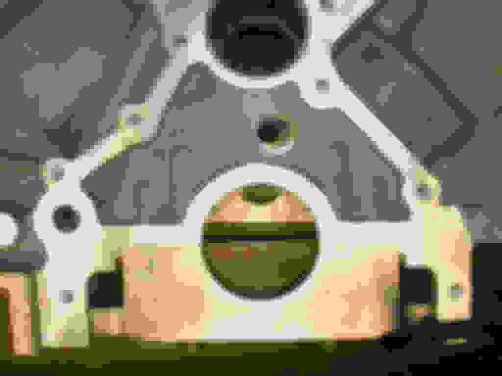
Question: After drilling your "vent holes", what do you do with the thrust bearing flange? Drill it too? Or just leave it?
After looking at the pictures again, I don't think it will go into the holes. They are a little lower than the machined surface for the thrust bearing flange.
Cool build! I'm not positive of it, but it seems to me from now owning an LS6, an ERL Superdeck, and an LS7, that the MID sleeve does the best job of cooling of the 3.
Also, I'm in to see the results! You rarely see big bore MID LS motors!
Wow!! I find that very interesting what you said about the cooling of each setup. It's great to hear from someone that have owned all 3 setups.... now I just need to gather my money up for Steve to hook me up on my block.
What kind of head gasket is going to seal those sleeves?
Hi Jontall,
Cometic have a range of gasket thickness's to suit the MID sleeves, they are not off the shelf but they make them pretty quickly, we settled on .040". IMO Cometic make the best gaskets in the world, I have used them on all sorts of race engines and many times been forced to re-use them without a problem.
After looking at the pictures again, I don't think it will go into the holes. They are a little lower than the machined surface for the thrust bearing flange.
You and me both, its vey clear that it wont, as they say "a picture is worth a thousand word's"
After looking at the pictures again, I don't think it will go into the holes. They are a little lower than the machined surface for the thrust bearing flange.
You're right! The thrust flange is shorter than I thought...
Can you tell me why that hole is needed and why it needs to be so large?
Hi JonTall,
Not trying to tell you how to "suck eggs" but the fact is piston's push air and gasses on both ends of the cylinder and moving anything takes energy. While the total interior volume of the crankcase remains constant as one piston goes up while another goes down, the displaced air has to move back and forth in the crankcase. If this is restricted in any way [relative to crankcase volume and rpm] this may not allow sufficient equalization between the pistons strokes, which can result in undesirable parasitic loss's in the engines efficiency.
Whilst we are running some 20" HG it's arguable that we don't need such a large vent hole however, we also run a very shallow billet dry sump pan that only just clears the crank, which also doesn't help the situation, so went with Steve's suggestion.
Cheer's,
Mark.
I was just curious because I never saw that done before. Thanks, Jon
Gas Monkey Built a 6-Wheel Ferrari Testarossa With a Corvette LT4 Engine
Slideshow: The controversial Ferrari F6 swaps its original flat-12 for a Corvette Z06-derived LT4 V8 and sends power to four rear wheels through a custom-built drivetrain.
7 Most Reliable High-Performance Engines GM Has Ever Built
Slideshow:These GM engines didn't just make huge power, they survived abuse, boost, track days, and six-digit mileage with a reputation for refusing to quit.
6 Common C5 Corvette Failures and What's Involved In Repairing Them
Slideshow: From wobbling harmonic balancers to failed EBCMs, these are the issues that define long-term C5 ownership and what repairs typically involve.
Retro Modern Bandit Pontiac Trans AM Comes With Burt Reynolds' Autograph
Slideshow: A modern Camaro transformed into a retro icon, this limited-run "Bandit" build blends nostalgia with brute force in a way few revivals manage.
Top 10 Greatest Cadillac V Series Performance Models Ever, Ranked
Slideshow: Cadillac didn't just crash the high-performance luxury vehicle party, it showed up loud, supercharged, and occasionally a little unhinged...
Coachbuilt N2A Anteros Is an LS2-Powered C6 Corvette In Italian Clothes
Slideshow: A one-off sports car that looks like a vintage Italian exotic-but hides a C6 Corvette underneath-just sold for the price of a new mid-engine Corvette.