When you click on links to various merchants on this site and make a purchase, this can result in this site earning a commission. Affiliate programs and affiliations include, but are not limited to, the eBay Partner Network.
So I talked with both the machine shop and MAST Motorsports today. The machinist started working on the block this week. They align honed the mains and we're decking the block today. The rotating assembly as it came from MAST did put the pistons "in the hole" as was expected. We did the calculations and settled on a zero deck height. With a combination of decking the block and milling the heads this will put the static compression ratio at 10.68:1 and the dynamic compression at about 8.68:1 (given the cam valve events). This will yield a quench / squish clearance right around 0.049".
Talking with both the machine shop and MAST they both agreed this is right in the range I want to be for this setup as a NA street car application.
Should be getting everything back later next week. Really looking forward to starting the pre-assembly!
That�s not a dcr and quench combo I�d want at all. What # did you use for ivc?
Hi bthomas, to answer the question the IVC is shown, along with the rest of the cam specs in the picture of the "cam card / spec sheet" that I posted last night. It is 47.4 ABDC (@ 0.050" lift). The rest of the specs are in the thread in earlier posts.
That being said I would like to hear your rationale for the Dynamic CR and quench not being a good combo. Not trying to question your opinion, I really do want to listen to your reasons. I am using a reputable machine shop / engine builder that does a lot of both all out race and street performance builds and has a lot of good reviews / feedback. I also spoke with the company that sold the rotating assembly (I know MAST Motorsports has a very good reputation for building all kinds of performance LS based engines). I went over all of the aspects of the build with them and they both are telling me this is in the range of where I want to be for a good street engine.
dcr is calculated at .006 which cam motion doesn�t list. But if your cam follows their standard ramp rate your ivc would be 75.5
recalculate with that and your dcr is going to be much lower
dcr is calculated at .006 which cam motion doesn�t list. But if your cam follows their standard ramp rate your ivc would be 75.5
recalculate with that and your dcr is going to be much lower
Alright now you have my attention. You are correct the cam specs sheet only list the IVC event @0.050" lift. Most of the online calculators that I've been referencing (Wallace racing, UEM, etc.) all calculate dynamic compression at 0.006". They say if your using the IVC spec'd @ 0.050" lift to add 15 degrees. My guess is that this is a best guess estimate. So using an IVC (@0.050") of 47.4 + 15 = 62.4. when I plug 62.4 into the calculators it winds up telling me I'd have to set static compression at 10.5:1 to yield 8.5:1 dynamic (given the rest of the engine parameters).
When I use the 75.5 you suggest, the calculators return a dynamic compression ratio of approx 7.8:1. So, first things first I will be calling Cam Motion tomorrow to get some more details and specs from them, in particular IVC @0.006" lift. Second thought is that this may not be a bad thing. If the dynamic CR will actually be closer to 7.8:1 (with the head gasket compressed thickness I have at the moment) yields a quench of approx 0.049" then I should pretty easily be able to change to a thinner head gasket and get a DCR closer to 8:1 or 8.5:1 and reduce the quench closer to 0.040". This is a good thing as it would only require swapping head gaskets and not require any additional machine work. I guess it will all come down to the actual cam IVC @0.006" spec from Cam Motion at this point.
Had a chance to speak with Cam Motion this morning. The cam they ground for me is using a XA236 intake lobe. They told me to add 27.5 degrees to the IVC @0.050" lift to get the IVC @0.006". So it is looking like IVC @ 0.006" lift will be 47.4+27.5= 74.9
I just re-calculated the DCR using the Wallace Racing online calculator and given the current engine specs and head gaskets it will wind up being 7.82:1 dynamic compression.
When I get everything back from the machine shop I plan to double and triple check everything. I do want to CC the combustion chambers using one of the liquid measuring kits this way I know for sure what the actual size is after milling the heads some. I will see where it all stands and do a pre-assembly mockup and check PTV clearance, actual quench clearance, etc. At that point I may decide to change to a thinner head gasket for the final assembly. I will wait and see how it all comes together. Fortunately it is looking like I will not be having to do any additional machine work (fingers crossed).
I will say that this is a good catch, so thank you to bthomas for bringing it to my attention!
Had a chance to speak with Cam Motion this morning. The cam they ground for me is using a XA236 intake lobe. They told me to add 27.5 degrees to the IVC @0.050" lift to get the IVC @0.006". So it is looking like IVC @ 0.006" lift will be 47.4+27.5= 74.9 I just re-calculated the DCR using the Wallace Racing online calculator and given the current engine specs and head gaskets it will wind up being 7.82:1 dynamic compression. When I get everything back from the machine shop I plan to double and triple check everything. I do want to CC the combustion chambers using one of the liquid measuring kits this way I know for sure what the actual size is after milling the heads some. I will see where it all stands and do a pre-assembly mockup and check PTV clearance, actual quench clearance, etc. At that point I may decide to change to a thinner head gasket for the final assembly. I will wait and see how it all comes together. Fortunately it is looking like I will not be having to do any additional machine work (fingers crossed). I will say that this is a good catch, so thank you to bthomas for bringing it to my attention!
yes so for example my cam motion cam is a 242/256 cam. If I remember correctly the duration at .006 is 53 degrees larger. So roughly 295/309 110+4. I plug these numbers into a valve event calculator and get the IVC event and plug that into a dynamic compression calculator. This number is 73.5. With 12.1 static compression I get about 9:1dcr. But altitude will also affect your cylinder pressure. Average DA here is 3500 and can go as high as 6500. At 3500 DA my dcr is about 8.3. Tighter quench will increase compression and dcr numbers but will actually increase detonation resistance. .036 - .04 with more compression is desirable versus trying to kill static compression by taking out all the quench and running say an ls9 gasket.
Where are you finding this rotating assembly on their site? I've looked all over and can only find a crank for $1921.....next is the 389 rotating assembly for $2685.
I was in a panic when I saw my dynamic compression came out to 10.25. Spoke with Bobby at Cam Motion and that's what I was told also. Add 27.5 to IVC. Actual DCR is 8.55 for my build. And for what it's worth, I used a .041 gasket with my pistons .007 or less out. Most were .005-6 above deck.
Had a chance to speak with Cam Motion this morning. The cam they ground for me is using a XA236 intake lobe. They told me to add 27.5 degrees to the IVC @0.050" lift to get the IVC @0.006". So it is looking like IVC @ 0.006" lift will be 47.4+27.5= 74.9
I just re-calculated the DCR using the Wallace Racing online calculator and given the current engine specs and head gaskets it will wind up being 7.82:1 dynamic compression.
When I get everything back from the machine shop I plan to double and triple check everything. I do want to CC the combustion chambers using one of the liquid measuring kits this way I know for sure what the actual size is after milling the heads some. I will see where it all stands and do a pre-assembly mockup and check PTV clearance, actual quench clearance, etc. At that point I may decide to change to a thinner head gasket for the final assembly. I will wait and see how it all comes together. Fortunately it is looking like I will not be having to do any additional machine work (fingers crossed).
I will say that this is a good catch, so thank you to bthomas for bringing it to my attention!
That is why I started to move away from the Mast assembly. I have no interest in using Cometics due to the Ra finish necessary on both the head and block. In my view, if you are having the block decked anyway, decking it to use a lower cost, readily available and more accommodating factory gasket would be preferable for a N/A moderate compression engine. Not a deal breaker either way though.
So I finally got everything back from the machine shop the other week. I've started doing a pre assembly and checking clearances and what not.
I will say that the crank journals are measuring out to be pretty much spot on for 0.010" undersize. I had the machine shop align hone the main caps as I'm using ARP main studs. I measured the mains with the ACL main bearings that came with the rotating assembly installed and it looks like I'm pretty much right at 0.0025" clearance.
I started on the road journals and checking bearing clearance. The rod journals on the crank are good. I'm coming up with 0.004" clearance on the rod big ends. Right now I'm thinking that actual rod journals themselves are too big. My guess is when MAST has them resized for the ARP bolts they took off too much material. Also it looks like the crank and the rods are at different ends of the tolerance range which is resulting in the 0.004" clearance. I'm going to triple check my measurements tonight and decide how to go forward. If something is off I'm hoping I can mix match bearings halves and get to where I need to be.
So I went and re measured everything (rod journals & bearing clearances) with a different bore gage and figured out what I believe was going on. I had been using a "3 point of contact" style bore gage for measuring everything. Here is a picture of the bore gage if your not familiar with them.
The gage has 3 anvils that expand outward to make contact on the i.d. of the bore your measuring. The setting ring shown in the picture is what you use to establish the diameter reference you are measuring against.
This worked great for the cylinders and main journals which have larger diameters. By the time I got to measuring the rod bearings the anvils were falling into the area of the bearing near the parting line which has an eccentric shape. The oval shape was throwing off the measurements. I went back and used a standard "single point of contact" style dial bore gauge and re-measured the rod bearings. Measuring in the direction along the length of the rods (perpendicular to the parting line) I wound up with 0.0028" clearance.
This is still a bit on the high side but at least is in the ballpark. I checked ACL's (bearing mfg) specs for the bearings that come with the rotating assembly (p/n 8B663H-010). They list a tolerance range for the crank journal dia. I see that the crank journals mic'd on the low side of that tolerance. So that combined with the rods having been resized for the ARP bolts is probably why the clearance is a little on the high side.
I called MAST and spoke to their tech line. They told me that the 0.0028" clearance would be fine for my application and suggested running 10W-40 oil and using a Melling high pressure high volume oil pump. Note, I'm using a C5 Corvette oil pan which 6+ quart capacity.
I also read over some documents that MAHLE published about their (Clevite bearings). They state for performance applications it is common recommend practice to use 0.001" of clearance per inch of journal diameter and then to add 0.0005" of additional clearance. That would work out to approx 0.0026" for the LS rod journals.
That all being said what does everyone think about the 0.0028" rod bearings clearance going with 10W-40 and the high pressure high volume oil pump?
I set up bearings according to power level and usage, intended rpm range, and compression. The “average” street build with 500ish flywheel hp…which is on the moderate side by todays standards, will see .0025 clearance numbers and have a long life with 35-40 lbs of oil pressure at idle with a standard volume/pressure pump…assuming lifter body to bore numbers are in check and cam bearing to journal numbers are in check of course. I’d have zero issues with .0028 numbers with a “mild” build and 40w oil personally. You will be fine with especially with that oil pump your planning. You might could even get by with a 30w oil, just have to see. Bearing numbers on the looser side will offer more forgiveness at rpm. I’ve seen .0045 in rod numbers, in the Cup world, so application and usage plays hand-in-hand in setting this stuff up.
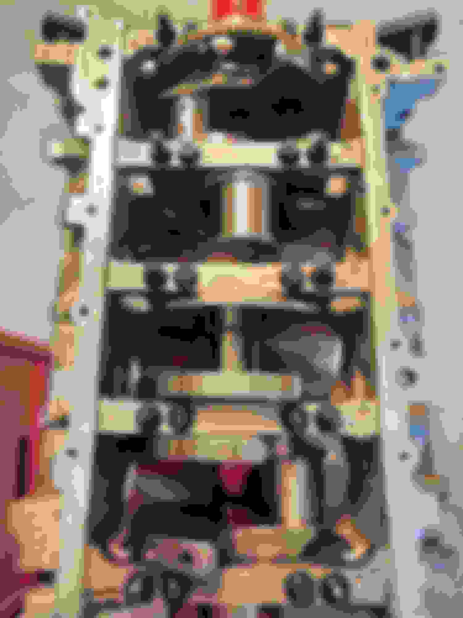
If anyone is interesting, here is a L8T crank installed into a L92 (gen 4 aluminum 6.2) block. No clearance issues with the counter weights. As far as clearances for the rotating assembly from MAST, so far I've not had to do anything other line hone the mains and have the rotating assembly balanced which included weight matching the rods.
I'll get to mocking up the rods and Pistons next week to check clearances and where I'm at with the deck height, quench and compression ratios.
Let me know if there are any specific pictures you'd like to see.
So I went and re measured everything (rod journals & bearing clearances) with a different bore gage and figured out what I believe was going on. I had been using a "3 point of contact" style bore gage for measuring everything. Here is a picture of the bore gage if your not familiar with them.
The gage has 3 anvils that expand outward to make contact on the i.d. of the bore your measuring. The setting ring shown in the picture is what you use to establish the diameter reference you are measuring against.
This worked great for the cylinders and main journals which have larger diameters. By the time I got to measuring the rod bearings the anvils were falling into the area of the bearing near the parting line which has an eccentric shape. The oval shape was throwing off the measurements. I went back and used a standard "single point of contact" style dial bore gauge and re-measured the rod bearings. Measuring in the direction along the length of the rods (perpendicular to the parting line) I wound up with 0.0028" clearance.
This is still a bit on the high side but at least is in the ballpark. I checked ACL's (bearing mfg) specs for the bearings that come with the rotating assembly (p/n 8B663H-010). They list a tolerance range for the crank journal dia. I see that the crank journals mic'd on the low side of that tolerance. So that combined with the rods having been resized for the ARP bolts is probably why the clearance is a little on the high side.
I called MAST and spoke to their tech line. They told me that the 0.0028" clearance would be fine for my application and suggested running 10W-40 oil and using a Melling high pressure high volume oil pump. Note, I'm using a C5 Corvette oil pan which 6+ quart capacity.
I also read over some documents that MAHLE published about their (Clevite bearings). They state for performance applications it is common recommend practice to use 0.001" of clearance per inch of journal diameter and then to add 0.0005" of additional clearance. That would work out to approx 0.0026" for the LS rod journals.
That all being said what does everyone think about the 0.0028" rod bearings clearance going with 10W-40 and the high pressure high volume oil pump?
Run it, you'll be fine with the .028 clearance. I run .025/025 rods and mains with a 10295 pump and Mobil 1 15-50 and pressure is excellent. That's with a shitty TBSS oil pan and overpriced PCM pickup in it.
Good info on CCW clearance as I have read that iron blocks require that but the aluminum ones do not. Not sure if a GTO/TBSS LS2 would need the extra machine work or not.
 02-22-2023, 03:55 PM