When you click on links to various merchants on this site and make a purchase, this can result in this site earning a commission. Affiliate programs and affiliations include, but are not limited to, the eBay Partner Network.
Need some expertise analysis on cause of failed rotating assembly
I had a recent failure of my rotating assembly and would like some help from those that have experienced, or have expertise in helping understand the what and why of the failure. Engine red-line was recently bumped up from 6800 to 7000 just prior to the failure. Engine was a LS2, OEM rods (with SPS rod bolts) and crank, Mahle pistons, Livernois stage II cam, and balance. SPS rod bolts I believe because of the stamp on end was "SPS 12.9" on the head of the bolt. What appeared to fail was the #1 rod bolt, but only speculating that was the cause, and not a result of something else. This is because one of the pieces of the bottom portion of the rod (not the cap) had a remaining threaded portion of the rod bolt still in that rod, where the bolt was snapped in half. Not sure if a rod bolt could be broken after something else failed, or if the bolt failure was what caused this mess. Anyway the result was the rod was broken into 3 pieces, the cap 3 pieces, and shrapnel everywhere. The block is cracked, and it appears the failure impacted the #2 rod as well, but to a lesser extent (#2 was broken, but still bolted around the crank journal).
Lubrication seemed to be sufficient (is an aftermarket dry sump). All journals except the 1-2 rod journals look great, as do the bearings. At this point I am posting some photos where I need some expertise to determine what damage I am looking at. The #1 rod crank journal has some odd coloring. On one side of the journal, no coloration, but on the opposite side of the same journal, it is nearly black, so I would like to have some thoughts on what/why that is. Secondly, a closeup of the #2 rod bearings is confusing to me. This bearing was still housed within the #2 rod. The #1 rod bearing (this was the rod that was completely destroyed) was wadded up in a ball, but did not have any of this scaling on the bearing material). Obviously, there is a lot of damage, but I cannot determine what caused this odd look of the bearing. Was it due to the immediate loss of oil pressure due to the adjacent rod leaving the journal at high RPM, or was this something else causing this (did low oil pressure cause the failure of the bearing, then rod, etc?). On one hand it appears to be a bearing failure of some sort, spalled somewhat, but more like it was ablated rather than spun off.
So…was this a failure of the bearing first, and if so why (am running a Dailey Engineering dry sump, and all other bearings are perfect), or was this a failure of the rod, or rod bolt, and the bearing appearance is a result of the calamity that took place?
Indication that I used SPS rod bolts
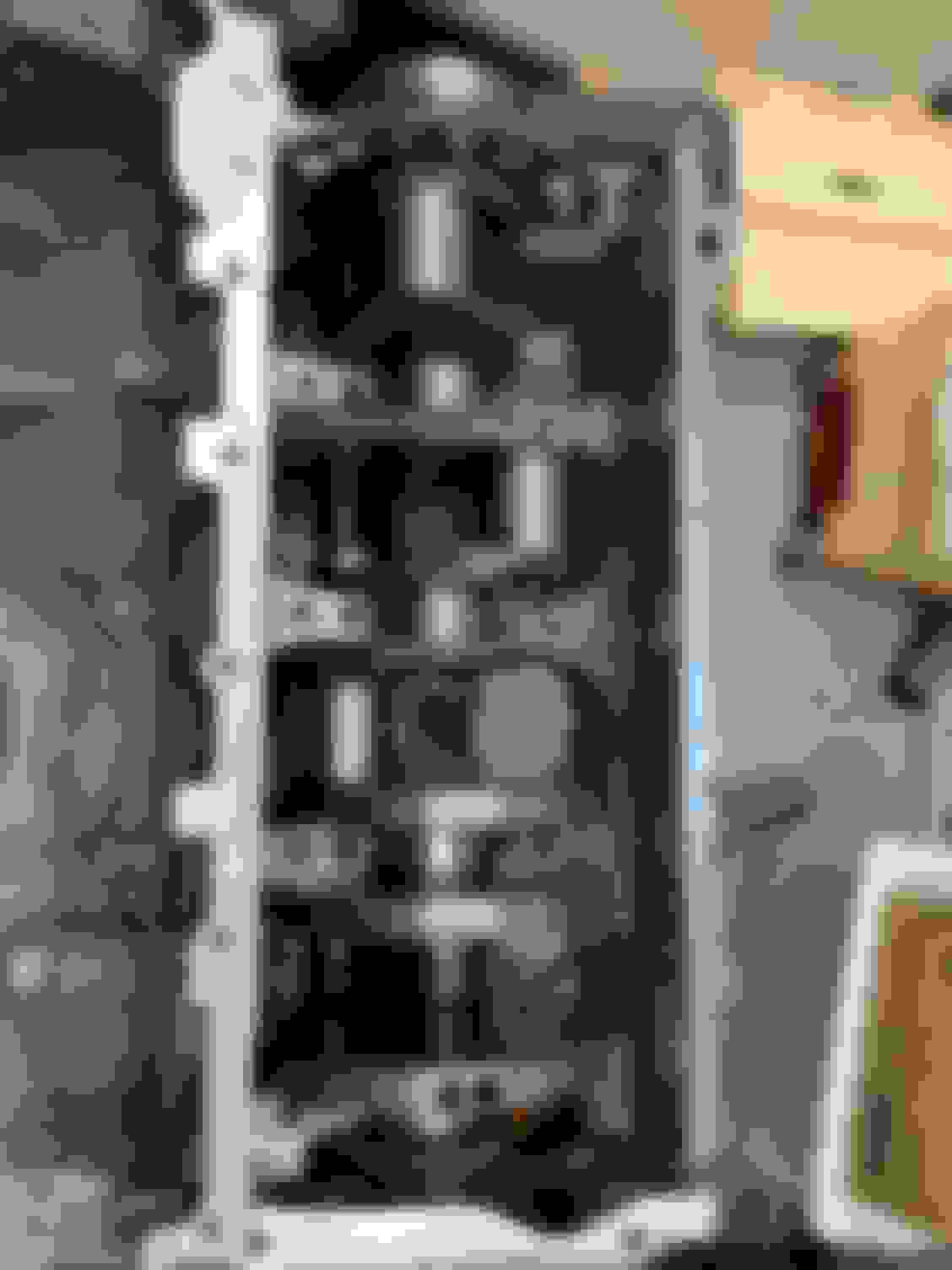
All journals looked great except for the failure
Beaten sided of the block inner wall
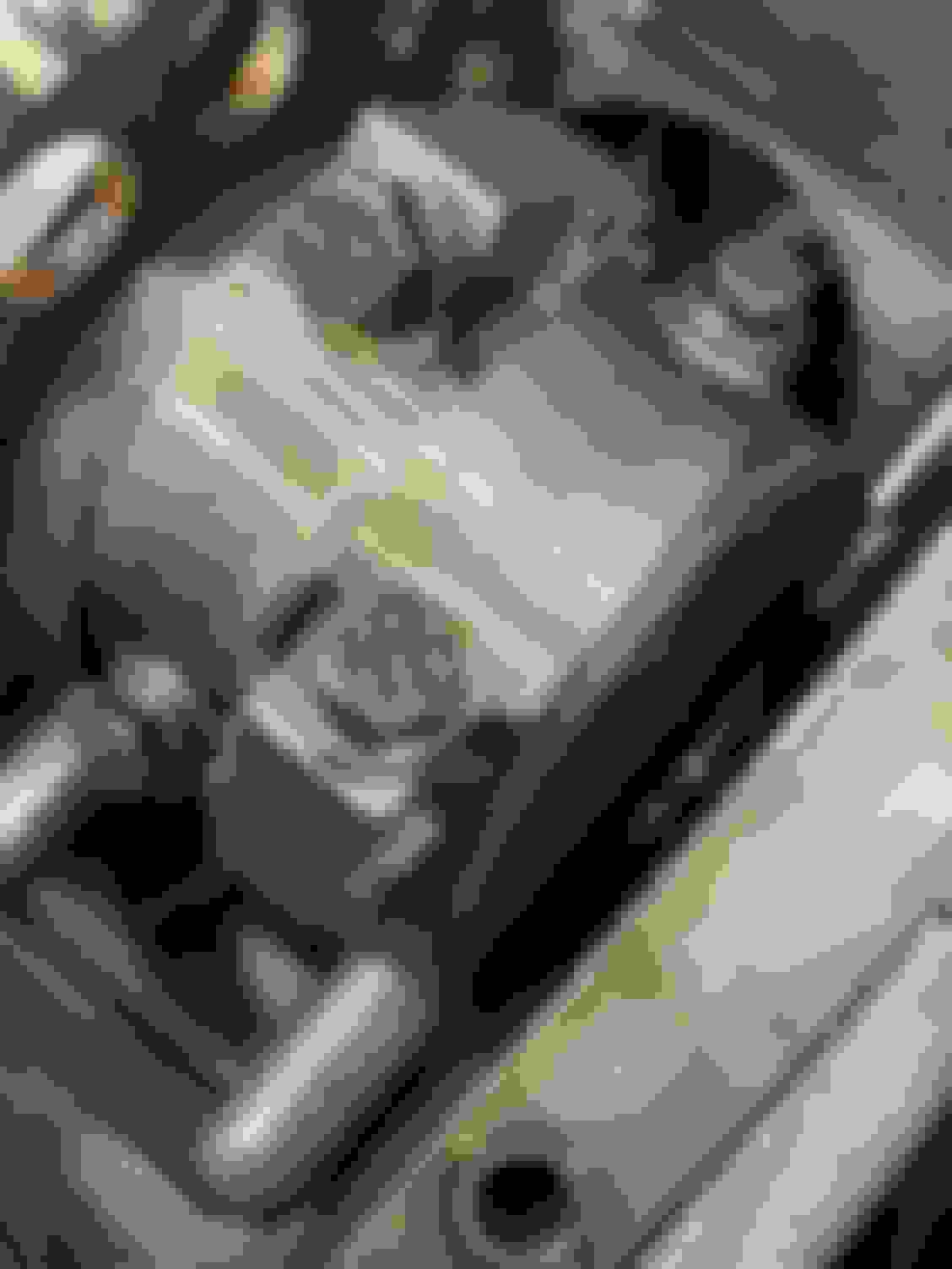
One side of the journal that had the failure
Opposite side of the same journal
Rod bearings of the #2 rod. #1 rod and bearing were pretty much obliterated.
Closeup of the other photo.
Comparison of number 3 rod bearing.
Last edited by blueovalz; Dec 9, 2023 at 05:03 PM.
I do not know the answer to that. Not sure if the following is pertinent to that question, but this motor had about 5000 miles on it, of which about half was asphalt track (road) racing before the failure. Rev limiter set to 6800 for years until just before the day the engine failed (set to 7000 for that event due to gearing/track configuration).
Not knowing what your clearances were setup to, and not knowing if the caps were resized would account for seeing something in the bearings outside of your failure.
that fact that it coincides with a rev limit change leads me to believe it was a rod failure. Typically a big end failure is from over rev. Btdt. Especially in a road course car, they are extra hard on rods from engine breaking/downshifts.
should a upgraded gen iv rod survived here? Probably, but again, don�t know the history. I�ve always suspected cracked cap rods should not be upgraded with hd bolts. Just outside design parameters.
Sorry my man. At least it died in battle, not in it's sleep.
What I think happened here is that at high RPM with a normal piston when the rod under tension it tries to turn 0 shaped instead of round, pinches the main bearing on the sides. This phenomenon is one reason high RPM V8 stuff runs more than the stock bearing clearance. Instantly gets hot as a pistol, and everything fails a fraction of a second later.
In my opinion, the big end went oval causing bearing clearances to collapse. Bearing immediately superheated which superheated the entire big end of the rod. This heat event caused the bolt failure and the rest is history. Total elapsed time at big RPM is about 2-3 seconds. It happens that fast.
Why did the rod go oval? I’m talking about a thousandth here. Rod bearings look worse to me at the parting lines, telling me that contact with the crank occurred there, reinforcing my idea of ovaling. It’s a gen 4 rod, and while it’s a great rod, it’s not rated to do what your doing with it, for the period of time that you’ve been doing this. I feel that the rods were round when assembled and this occurred lately…maybe after you bumped up the limiter. I say this because the build has 5k miles on it. It would have NEVER lasted 5k hard miles if the rods were out of round to begin with.
….edit…Kawboom said same thing while I was typing. Treed me…
Would the out of round show-up by using plastiguage?
Plastiguage is ok in a pinch. To properly and correctly measure the big ends, you need a dialbore gauge. It will measure out 4 zeros�ten thousandth of an inch. Plastiguage won�t do that. Keep in mind that the rod big end has elasticity. It won�t measure out on a bench, to what that rod is seeing at 7k rpm.
@blueovalz, can you measure the out of roundness with a dial bore gauge?
I'm interested to see how out of round the higher clamping force is with upgraded fasteners.
@blueovalz, can you measure the out of roundness with a dial bore gauge?
I'm interested to see how out of round the higher clamping force is with upgraded fasteners.
Dial bore gauge may not indicate what you're hoping to see, but it will tell the truth! As to whether you can measure the out-of-roundness, yes. It'll measure size, taper, and out-of-roundness.
Every rod bearing made for an engine is actually oval shaped. The big end of the rod itself is round, but the the bearing tapers on the ends so its () shaped with extra clearance on the side next to the bolts, allowing the tension of high RPM rotation to pull the rod closer to round, but it can be overridden with enough RPM and make the rod go 0 shaped and pinch the main.
Bearing got hot and tried to weld to crank, clearance got loose from material loss and it jackhammered the bolt and pulled it. As to why, detonation can cause it, also I'm not for installing aftermarket bolts in stock LS rods, more clamping force distorts the rod end and can tighten up bearing clearances, because they are cracked cap rods you cannot resize them.
Gas Monkey Built a 6-Wheel Ferrari Testarossa With a Corvette LT4 Engine
Slideshow: The controversial Ferrari F6 swaps its original flat-12 for a Corvette Z06-derived LT4 V8 and sends power to four rear wheels through a custom-built drivetrain.
7 Most Reliable High-Performance Engines GM Has Ever Built
Slideshow:These GM engines didn't just make huge power, they survived abuse, boost, track days, and six-digit mileage with a reputation for refusing to quit.
6 Common C5 Corvette Failures and What's Involved In Repairing Them
Slideshow: From wobbling harmonic balancers to failed EBCMs, these are the issues that define long-term C5 ownership and what repairs typically involve.
Retro Modern Bandit Pontiac Trans AM Comes With Burt Reynolds' Autograph
Slideshow: A modern Camaro transformed into a retro icon, this limited-run "Bandit" build blends nostalgia with brute force in a way few revivals manage.
Top 10 Greatest Cadillac V Series Performance Models Ever, Ranked
Slideshow: Cadillac didn't just crash the high-performance luxury vehicle party, it showed up loud, supercharged, and occasionally a little unhinged...
Coachbuilt N2A Anteros Is an LS2-Powered C6 Corvette In Italian Clothes
Slideshow: A one-off sports car that looks like a vintage Italian exotic-but hides a C6 Corvette underneath-just sold for the price of a new mid-engine Corvette.