


Inside the LS7 Intake.......Pics inside
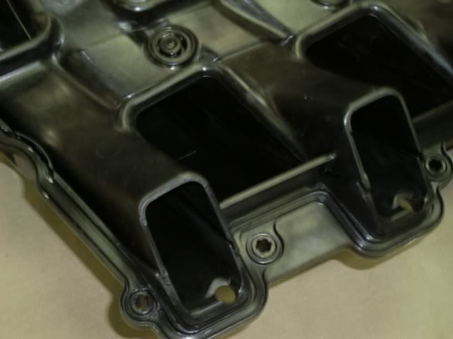
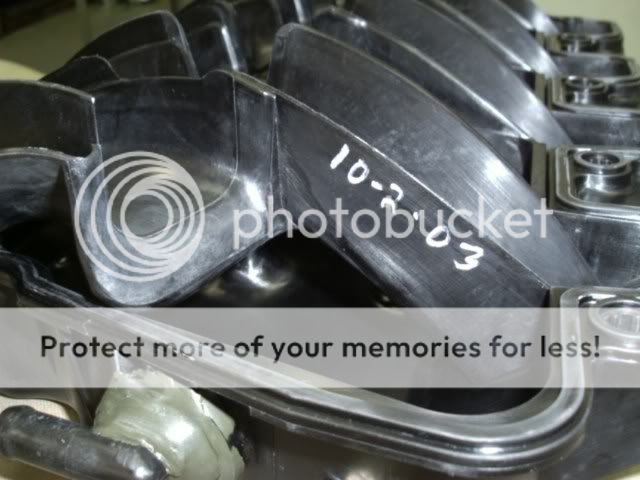
Well........curiosity got the cat I'm afraid. I just HAD to see the inside of an LS7 intake. I figured this would be helpful to others on this site as well. Note the date on the runner wall.
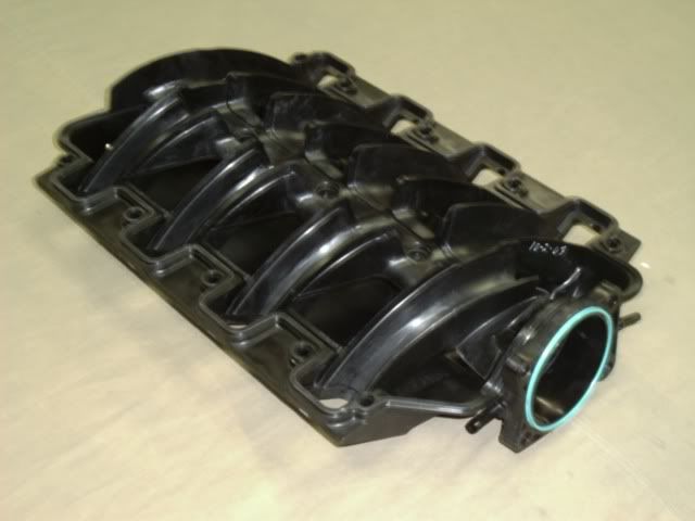
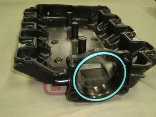
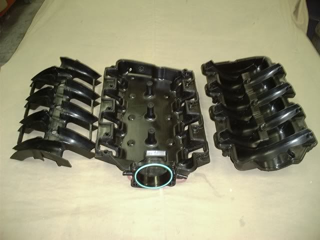
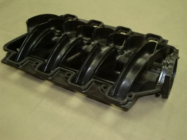
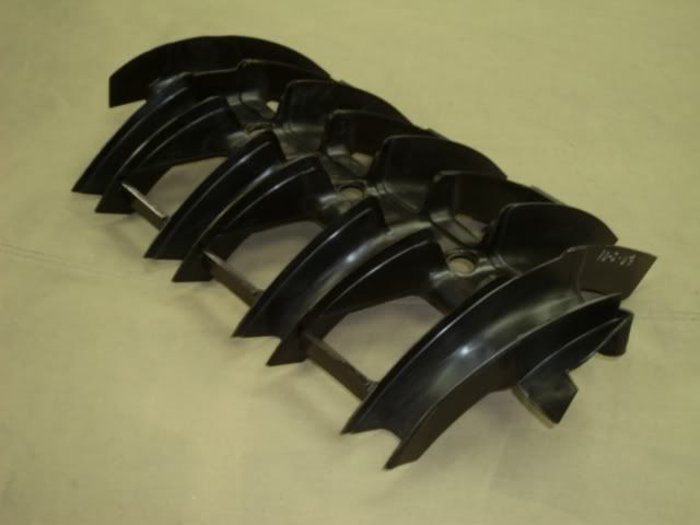
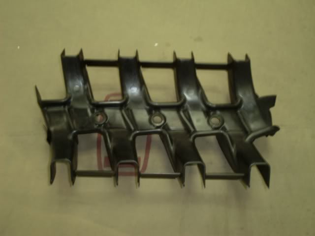
These manifolds are a slick modular design similar to the FAST intakes. This manifold did not have a part number on it.
Richard
These manifolds are a slick modular design similar to the FAST intakes. This manifold did not have a part number on it.
Richard
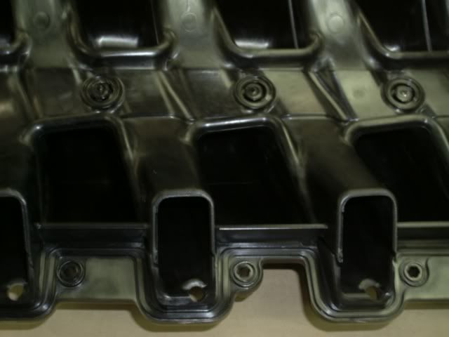
Sorry John.......forgot to include the runner length. Measuring down the runner centerline, the runner is 11.0" in length.
Your correct about the born on date. I'm guessing this is a pre production part?
Richard
Your correct about the born on date. I'm guessing this is a pre production part?
Richard
Yes, I thought the runners looked pretty short. How does the runner length compare to the LS1-style manifolds?
__________________

2013 Corvette Grand Sport A6 LME forged 416, Greg Good ported TFS 255 LS3 heads, 222/242 .629"/.604" 121LSA Pat G blower cam, ARH 1 7/8" headers, ESC Novi 1500 Supercharger w/8 rib direct drive conversion, 747rwhp/709rwtq on 93 octane, 801rwhp/735rwtq on race fuel, 10.1 @ 147.25mph 1/4 mile, 174.7mph Half Mile.
2016 Corvette Z51 M7 Magnuson Heartbeat 2300 supercharger, TSP LT headers, Pat G tuned, 667rwhp, 662rwtq, 191mph TX Mile.
2009.5 Pontiac G8 GT 6.0L, A6, AFR 230v2 heads. 506rwhp/442rwtq. 11.413 @ 121.29mph 1/4 mile, 168.7mph TX Mile
2000 Pewter Ram Air Trans Am M6 heads/cam 508 rwhp/445 rwtq SAE, 183.092 TX Mile
2022 Cadillac Escalade 6.2L A10 S&B CAI, Corsa catback.
2023 Corvette 3LT Z51 soon to be modified.
Custom LSX tuning in person or via email press here.
Originally Posted by Richard@WCCH


Richard
Is that epoxy on the brake booster elbow in the pic with the date visible?
What's odd is that recessed "pocket" right behind the TB opening showing on the first pic.
Trending Topics
It doesn't appear that these intakes are welded together like the LS6 and truck intakes. This is the only LS7 intake I have in the shop right now but I've heard that the production manifolds have screws on the bottom holding them together like this one. This intake came apart fairly easy. I suspect it was taken apart once before. I'm not sure how the inside of this intake will vary from the rest but I figured since I had the opportunity to share this we all might learn something.
Richard
Richard
LS1 Tech Stories
The Best V8 Stories One Small Block at Time

6 Common C5 Corvette Failures and What's Involved In Repairing Them
Pouria Savadkouei
Retro Modern Bandit Pontiac Trans AM Comes With Burt Reynolds' Autograph
Verdad Gallardo
Top 10 Greatest Cadillac V Series Performance Models Ever, Ranked
Pouria Savadkouei
Top 10 Most Powerful Chevy Trucks Ever Made!

Hennessey's New Supercharged Silverado ZR2 Has 700 HP
Verdad Gallardo
Coachbuilt N2A Anteros Is an LS2-Powered C6 Corvette In Italian Clothes
Verdad Gallardo
Awesome K5 Blazer Restomod Comes With C7 Corvette Power
Verdad Gallardo
10 Camaros You Should Never Buy

10 LS Engine Myths That Refuse to Die
Verdad Gallardo
Thank you for posting.
Based on your observations, does this intake look robust enough to be used for forced induction? Since it's not 'welded' I am slightly concerned how tough it will be when 20 psi is thrown at it (having not seen one).
Thanks again!
Based on your observations, does this intake look robust enough to be used for forced induction? Since it's not 'welded' I am slightly concerned how tough it will be when 20 psi is thrown at it (having not seen one).
Thanks again!


so whats similar/different between this and the F.A.S.T. intake? and was the F.A.S.T. out before Oct 2003? i wonder if there was a little reverse engineering on somebody's part.


Teching In
Joined: Feb 2005
Posts: 32
Likes: 0
From: Montana, USA
I just have to ask/propose the obvious: Can the L92 manifold be dissected in a similar manner? I.e. is it welded, or perhaps like the LS7, just epoxied together?
If so, the issues of the too-tall-for-an-f-body manifold and long runners optimized for midrange torque are a very simple fix.
And of course in a perfect world, one would just be able to take the center and top sections of the LS7 manifold and slap them onto the L92 bottom section, mated to those gorgeous heads.
Ah, what dreams may come?
it was probably from a prototype run. my buddy works at 3d design services and they sometimes make a handful of a part for pre production projects. they have a ls1 manifold hanging on the wall from 1996.
Originally Posted by JustAnIlluzion
it was probably from a prototype run. my buddy works at 3d design services and they sometimes make a handful of a part for pre production projects. they have a ls1 manifold hanging on the wall from 1996.

Some have questioned the epoxy on the vacuum tube. I far as I can see, it's just holding the tube in place. Perhaps it was broken off when the intake was originally separated? I reinspected the inside of the intake and there is absolutely no epoxy anywhere inside. I'll try and get some pics of the intake fitted to the heads. This intake will provide some perspective when bolting up to the standard LS7 or other heads.
Richard

