LS1/LS2/LS6 intake swap Sticky!!!
 11-16-2011 | 07:11 PM
#81


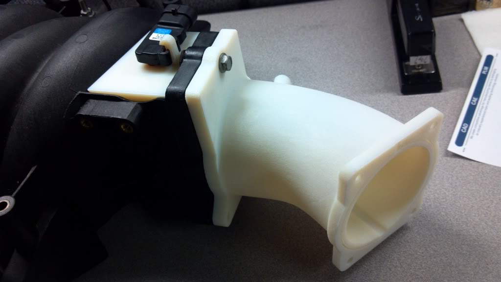
Map sensor adapter is a go, fits very nicely.
TB adapter now has a provision for a GM LS4 thottle body gasket (about $7 I think) so it'll seal up. the only thing left to do is find the right thread call out for the GM throttle body bolts. I made stand offs that will be internally threaded so hopefully there will be no need for backing nuts on the piece. I need to get it made complete so I can bolt it all up and drive it around for a bit to see if the plastic will warp over time, and if so I just need to add support ribs along the tube to strengthen it up. Otherwise it looks pretty close to being ready to go.
TB adapter now has a provision for a GM LS4 thottle body gasket (about $7 I think) so it'll seal up. the only thing left to do is find the right thread call out for the GM throttle body bolts. I made stand offs that will be internally threaded so hopefully there will be no need for backing nuts on the piece. I need to get it made complete so I can bolt it all up and drive it around for a bit to see if the plastic will warp over time, and if so I just need to add support ribs along the tube to strengthen it up. Otherwise it looks pretty close to being ready to go.
11-18-2011 | 11:05 AM
#82
the first throttle body adapter is being made right now. Im pretty nervous because its gonna take a while to make and i just hope its not a botched piece. Ill know more on Monday when i get the parts. That is unless i swing by the office sometime this weekend and get it, but dont know if ill have time for that.
11-19-2011 | 10:47 AM
#84
GM has put the map sensor in several locations on different vehicles.
05-06 LS4 it's behind the throttle body, the 07-08 LS4 it was moved to the top of a runner at middle of the intake
LS1/6 was on a plastic elbow at the rear of the manifold
LS2/7 is located near the throttle body. It's about the same distance away from the TB as my part sets it on a LS1 intake, but it is off to the passenger side of the manifold by a couple inches
Truck intakes it's located on the top of the runners, in the middle of the intake
So what is "best" I'm not sure with because all it is reading is pressure, which it should be able to do at all of the locations.
11-20-2011 | 10:12 PM
#85
GM has put the map sensor in several locations on different vehicles.
05-06 LS4 it's behind the throttle body, the 07-08 LS4 it was moved to the top of a runner at middle of the intake
LS1/6 was on a plastic elbow at the rear of the manifold
LS2/7 is located near the throttle body. It's about the same distance away from the TB as my part sets it on a LS1 intake, but it is off to the passenger side of the manifold by a couple inches
Truck intakes it's located on the top of the runners, in the middle of the intake
So what is "best" I'm not sure with because all it is reading is pressure, which it should be able to do at all of the locations.
05-06 LS4 it's behind the throttle body, the 07-08 LS4 it was moved to the top of a runner at middle of the intake
LS1/6 was on a plastic elbow at the rear of the manifold
LS2/7 is located near the throttle body. It's about the same distance away from the TB as my part sets it on a LS1 intake, but it is off to the passenger side of the manifold by a couple inches
Truck intakes it's located on the top of the runners, in the middle of the intake
So what is "best" I'm not sure with because all it is reading is pressure, which it should be able to do at all of the locations.
11-21-2011 | 12:24 PM
#86
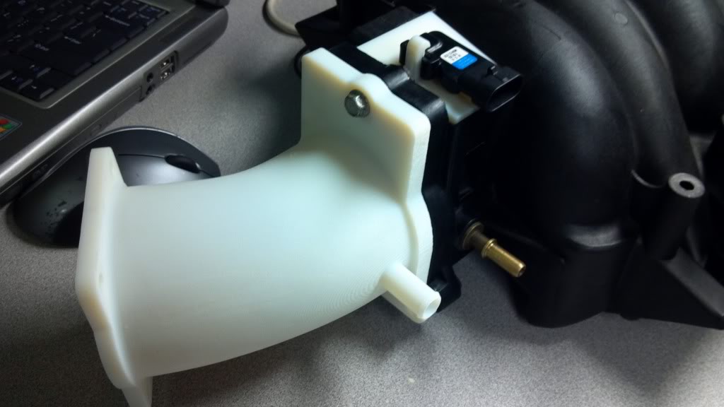
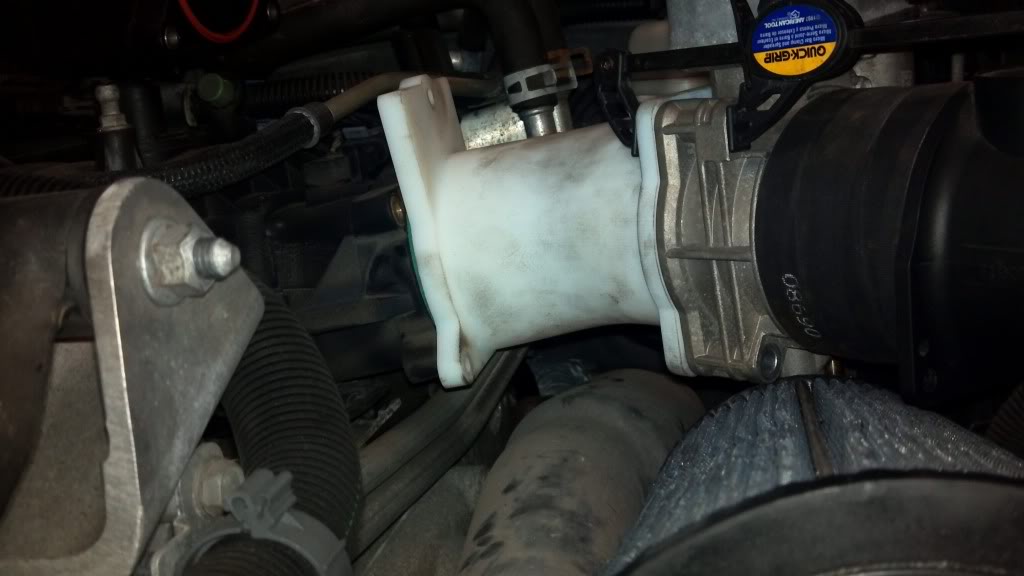
first prototype TB adapter is done.....and needs work already. but thats what prototypes are for.
here it is mocked up on the intake. ill hopefully be able to get the needed modifications done this week and printed over the weekend so i can have it for next week.
here it is mocked up on the intake. ill hopefully be able to get the needed modifications done this week and printed over the weekend so i can have it for next week.
11-21-2011 | 03:37 PM
#87
What kind of material are you using, and will the final pieces be in black?
The TB adapter looks pretty bad ***, but will push the TB and the MAF sensor way foward. Possible clearance issues?
The TB adapter looks pretty bad ***, but will push the TB and the MAF sensor way foward. Possible clearance issues?
11-21-2011 | 04:06 PM
#88
the material here is a polymer made for prototyping. the final will be made of a ABS like material and if i need to, for structural integrity, I can have it plated which will add a bit of strength. It will have a greenish color out of teh machine, but its all paintable, or plateable. as for fitment issues it would most certainly be an issue for someone who has a fixed box type setup like yourself. but for me, i plan on building a fender well style intake in the future which this will help with minimizing restrictive bends in the overall system.
11-21-2011 | 04:15 PM
#89
the material here is a polymer made for prototyping. the final will be made of a ABS like material and if i need to, for structural integrity, I can have it plated which will add a bit of strength. It will have a greenish color out of teh machine, but its all paintable, or plateable. as for fitment issues it would most certainly be an issue for someone who has a fixed box type setup like yourself. but for me, i plan on building a fender well style intake in the future which this will help with minimizing restrictive bends in the overall system.
11-22-2011 | 11:02 AM
#90
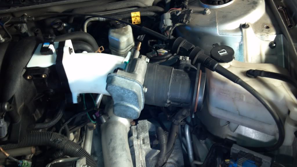
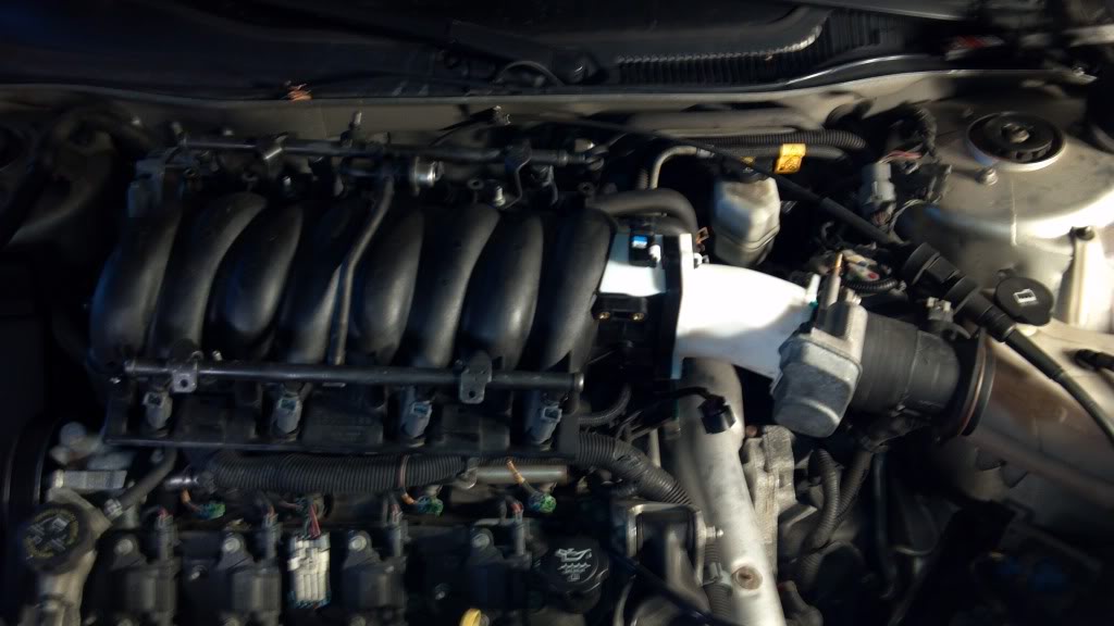
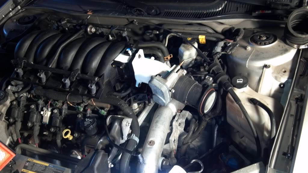
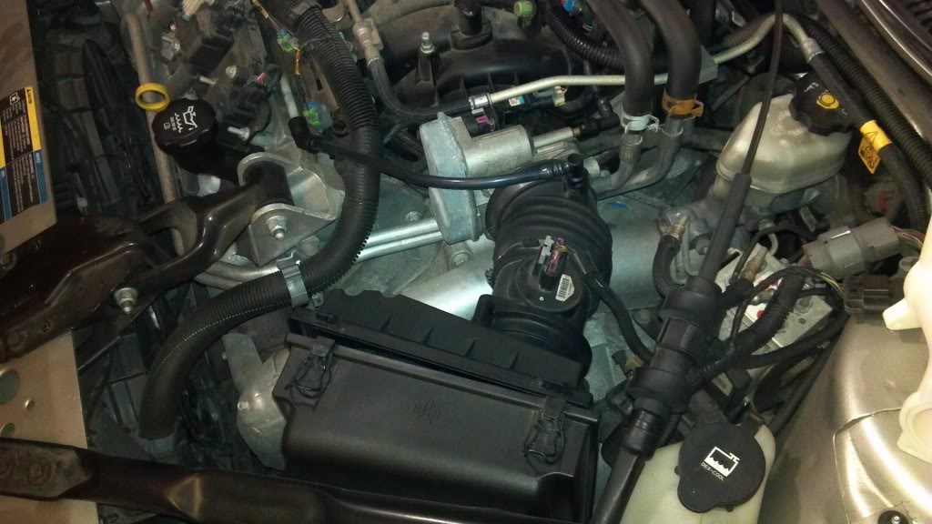
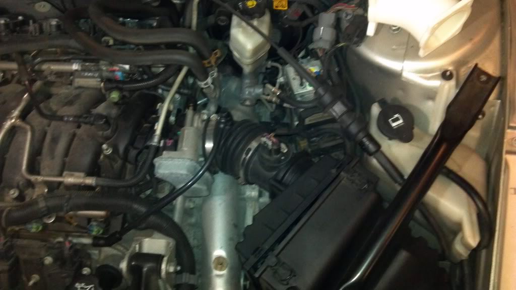
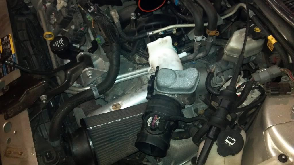
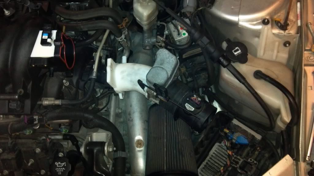
so i halfway mocked it up last night to just see what i was up against. my first thing i noticed (after i built it) is i rotated my TB 90* to where it should be, no biggie though as i still got a good idea of what it looks like. So i need to make a few adjustments to it, but i think it is really close for a first run part with no dimensions to work off of under the hood other than my eyecrometer. so here are the pics of it mocked up and reference the stock setup so you can see how it sits compared to that. Also remember this is hooked up to the LS4 intake so it will sit slightly different on the LS1 intake when installed. Sorry for the camera phone quality.
Stock setup
New TB adapter with TB and MAF attached
Stock setup
New TB adapter with TB and MAF attached
11-22-2011 | 03:16 PM
#92
TECH Fanatic
Joined: Oct 2003
Posts: 1,101
Likes: 0
looks pretty cool.
is there going to be enough give in the system to allow the engine to move? i know some of the camaro guys had issue when swapping to different materials from the throttle body to the maf, the engine moved enough to crack the airlid.
is there going to be enough give in the system to allow the engine to move? i know some of the camaro guys had issue when swapping to different materials from the throttle body to the maf, the engine moved enough to crack the airlid.
11-22-2011 | 03:21 PM
#93
Attempt is good word to use  ....after i get the TB adapter squared away i still need to modify the bottom of the intake and the valley cover. My biggest fear is screwing up the sensor in the tray or not getting the piece welded in on the right angle. So i dont know exactly when ill be getting to this, but its either going to be over the winter or waiting till spring time. but itll be be done for next year. I have a few other things id like to do to aid in freeing up some HP, but i wont get into all that in here.
i dont think its a concern here. the silicone couplers should allow any flex needed for it to move. plus its all mounted to the engine, not the body so it will move with the engine.the airlid is mounted to the car, the TB/MAF are attached to eht engine so if there is no flex something has to give. not the case with our cars unless you have everything welded up and a air box deal.
....after i get the TB adapter squared away i still need to modify the bottom of the intake and the valley cover. My biggest fear is screwing up the sensor in the tray or not getting the piece welded in on the right angle. So i dont know exactly when ill be getting to this, but its either going to be over the winter or waiting till spring time. but itll be be done for next year. I have a few other things id like to do to aid in freeing up some HP, but i wont get into all that in here.i dont think its a concern here. the silicone couplers should allow any flex needed for it to move. plus its all mounted to the engine, not the body so it will move with the engine.the airlid is mounted to the car, the TB/MAF are attached to eht engine so if there is no flex something has to give. not the case with our cars unless you have everything welded up and a air box deal.
Last edited by Dom87SS; 11-22-2011 at 03:27 PM.
 03-09-2012 | 02:16 PM
#97
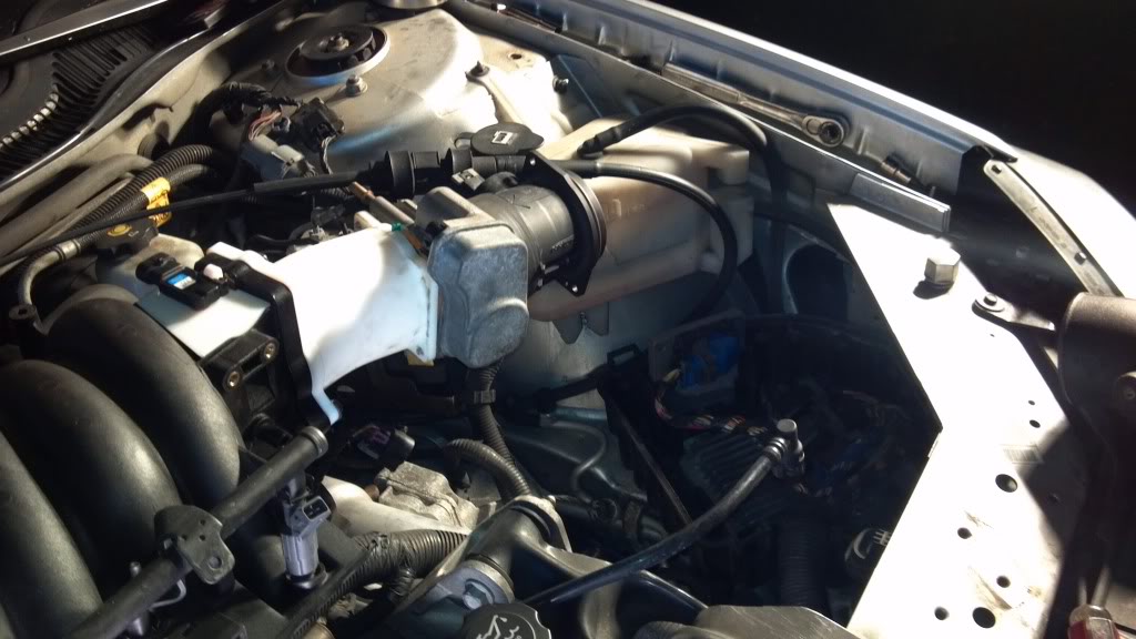
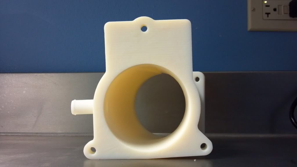
new revision of my TB adapter is being printed right now, itll be done tomorrow Am. I need to go past the office tomorrow anyway so im going to swing in and pick it up after its done. Hopefully to at least test fit the throttle body on it on sunday.
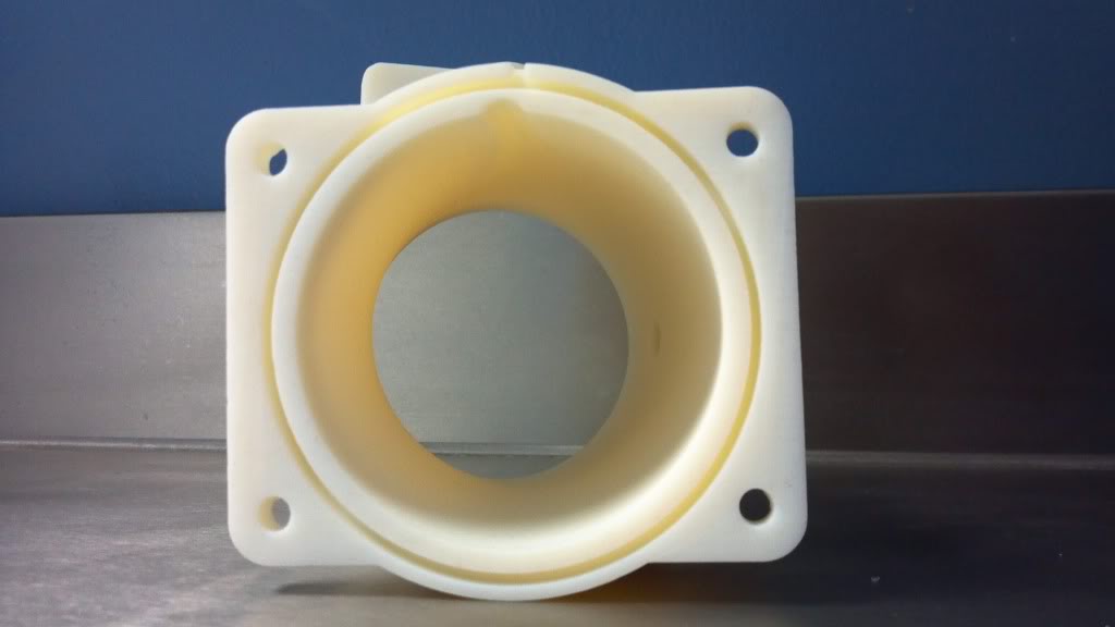
here is a in progress build of it right now

here is a in progress build of it right now
 03-11-2012 | 04:28 PM
#99
So I think I have a winner here, one more piece to the puzzle complete. dumI need to make a FWI now, modify the bottom of the intake, plug the rear, get a alternator bracket to modify, and DOD connector to modify.dum