


PCV Exit As Vacuum Source?
Ok great, but you still have the manifold tied to the can, where during WOT there will be pressure, which makes no sense. How does this protect the turbo compressor inlet? What was the point of the can? Where is the low pressure source during boost for the crank case? And one more, why would we go out of our way, that is why would we go through the trouble of adding another valve, another point of failure, to the engine crankcase system? Its like you said "Well, there arnt enough places for **** to leak so lets add another valve and extra plumbing/lines so its less reliable. "
Last edited by kingtal0n; Feb 28, 2016 at 08:27 PM.
I have no idea. My setup is NA. I'm not worried about boost. I got an MM can to help with excessive crankcase pressure. I'm sure MM will chime back in to answer that for you. I do know that he makes a great product and his customer service in also great. There are also plenty of boosted setups running one of his cans.
11 Second Club
Joined: Mar 2012
Posts: 1,541
Likes: 15
From: South Florida
Ok great, but you still have the manifold tied to the can, where during WOT there will be pressure, which makes no sense. How does this protect the turbo compressor inlet? What was the point of the can? Where is the low pressure source during boost for the crank case? And one more, why would we go out of our way, that is why would we go through the trouble of adding another valve, another point of failure, to the engine crankcase system? Its like you said "Well, there arnt enough places for **** to leak so lets add another valve and extra plumbing/lines so its less reliable. "
TECH Addict
Joined: Dec 2010
Posts: 2,610
Likes: 4
From: Maricopa, AZ
Ok great, but you still have the manifold tied to the can, where during WOT there will be pressure, which makes no sense. How does this protect the turbo compressor inlet? What was the point of the can? Where is the low pressure source during boost for the crank case? And one more, why would we go out of our way, that is why would we go through the trouble of adding another valve, another point of failure, to the engine crankcase system? Its like you said "Well, there arnt enough places for **** to leak so lets add another valve and extra plumbing/lines so its less reliable. "
The Blue line runs from between the filter and the compressor to the crankcase vent with a hollowed out PCV valve as an adapter (so no check valve).
The Green line goes from the catch can to the intake plenum, this line does have a check valve.
The Red line runs from the catch can to the crankcase too, no check valve.
Under low/vacuum loads air is drawn into the crankcase via the blue line, crankcase is evacuated through the red line to the catch can, then to the intake plenum.
Under boost the check valve on the catch can closes. Air is drawn into the crankcase via the catch can/filter and pulled out through the blue line via the Venturi effect pre-compressor.
What you don't know is that the LT1 intake manifold has a designed port to the crankcase on it with a pretty decent oil baffle design already on it. So, while under boost, the flow of the crankcase through the intake is as factory designed. And the amount of oil getting into the compressor is negligible. Could you put a catch can there for peace of mind? Sure. Is it needed? Only if you have other more serious issues going on and you're trying to band aid something else.
The reason there is a catch can between the red and green lines is because the oil baffling on that part of the crankcase vent is poor (stock this was designed to be the fresh air inlet port), so the catch can is there to keep oil from getting into the plenum. But it's not needed on the Blue line because there's already a "catch can" installed on the bottom of the intake manifold (in the valley).
this is the exact opposite of what the other fellow just said,
Originally Posted by huntr1117
The filter on top has a one way valve inside of it. It will not suck air in. It only opens to relieve excess crankcase pressure at or near WOT. During normal driving/idle it remains shut.
Sounds like the can is setup to vent to the atmosphere, exactly like a breather on a valve cover. NO PCV ACTION. Neither way is because even if by some magic the blue line is also a crankcase evacuation port, you have just added a significant volume to the crankcase which will further diminish the PCV signal supplied by the compressor inlet. The line from compressor to can needs to be as short as possible for best pressure signal. Or else, If installed to the trouble side, as you put it, there is still a connection to the compressor inlet through the engine block to the other side (blue line) which means these two sides share pressure signals, i.e. pressure in the blue line will also be detectable in the red line leading to the can. Except of course for the diminishing signal as the lines get longer and longer- see where I am going? The additional lines are killing the pcv signal to the red line side, to the catch can. If P1 is the compressor inlet, and P2 is in the can, P1 < P2 and the difference becomes larger and larger the farther you get from the P1. Since there is a check valve on the green line side of the can, air cannot flow this direction so it must exit via the filter on the top of the can as implied previously, as opposed to being connected directly to the blue line side (compressor inlet) for some reason. This is an acceptable way of protecting the intake plenum, Ill agree to that, but there is very little to any pcv action implied.
Last edited by kingtal0n; Feb 28, 2016 at 09:59 PM.
TECH Addict
Joined: Dec 2010
Posts: 2,610
Likes: 4
From: Maricopa, AZ
this is the exact opposite of what the other fellow just said,
Which is it?
Sounds like the can is setup to vent to the atmosphere, exactly like a breather on a valve cover. NO PCV ACTION. Neither way is because even if by some magic the blue line is also a crankcase evacuation port, you have just added a significant volume to the crankcase which will further diminish the PCV signal supplied by the compressor inlet. The line from compressor to can needs to be as short as possible for best pressure signal. Or else, If installed to the trouble side, as you put it, there is still a connection to the compressor inlet through the engine block to the other side (blue line) which means these two sides share pressure signals, i.e. pressure in the blue line will also be detectable in the red line leading to the can. Except of course for the diminishing signal as the lines get longer and longer- see where I am going? The additional lines are killing the pcv signal to the red line side, to the catch can. If P1 is the compressor inlet, and P2 is in the can, P1 < P2 and the difference becomes larger and larger the farther you get from the P1. Since there is a check valve on the green line side of the can, air cannot flow this direction so it must exit via the filter on the top of the can as implied previously, as opposed to being connected directly to the blue line side (compressor inlet) for some reason. This is an acceptable way of protecting the intake plenum, Ill agree to that, but there is very little to any pcv action implied.
Sorry, I can see why you would want a can protecting the manifold on aproblem side, didn't mean to over complicate it. I just noticed that the compressor inlet was only seemed to be on one side of the engine, seems awkward and almost like another line is missing (from can -> red -> compressor inlet) but I can see how having two is even more plumbing/mess and complexity thus I reason the vent. It isn't optimal but it works in a pinch to protect the manifold from a poor baffle, I agree to that.
TECH Addict
Joined: Dec 2010
Posts: 2,610
Likes: 4
From: Maricopa, AZ
Sorry, I can see why you would want a can protecting the manifold on aproblem side, didn't mean to over complicate it. I just noticed that the compressor inlet was only seemed to be on one side of the engine, seems awkward and almost like another line is missing (from can -> red -> compressor inlet) but I can see how having two is even more plumbing/mess and complexity thus I reason the vent. It isn't optimal but it works in a pinch to protect the manifold from a poor baffle, I agree to that.
LS1 Tech Stories
The Best V8 Stories One Small Block at Time

Top 10 Greatest Cadillac V Series Performance Models Ever, Ranked
Pouria Savadkouei
Top 10 Most Powerful Chevy Trucks Ever Made!

Hennessey's New Supercharged Silverado ZR2 Has 700 HP
Verdad Gallardo
Coachbuilt N2A Anteros Is an LS2-Powered C6 Corvette In Italian Clothes
Verdad Gallardo
Awesome K5 Blazer Restomod Comes With C7 Corvette Power
Verdad Gallardo
10 Camaros You Should Never Buy

10 LS Engine Myths That Refuse to Die
Verdad Gallardo
Five Reasons the Camaro Was the Most Pivotal Player in the Pony Car Wars 2.0
Brett Foote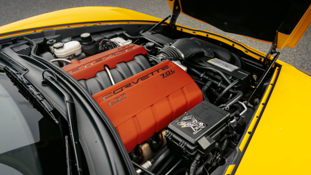
10 Reasons the LS7 Is GM's Most Extreme Naturally Aspirated V8 Engine Ever
Verdad Gallardo regardless, the crank case from oil pan to valve cover is all connected. Pull from one valve cover, you pull from both, there is just a differential of pressure through the crank case. I think the green line should T into the compressor inlet for best results, and do away with the silly extra valve and atmospheric filter. But I can also understand if that would make the plumbing difficult, complex, cumbersome, which is why it wasn't done.


You cannot Tee-in an open air source to the manifold vacuum (green line). It would be a major vacuum leak not to mention completely defeat PCV.
Read the corner text? It explains everything.

The way you have it hooked up to that ricer is not a complete PCV system, it is either not one at all (draft only,scavenging and unrelated to this thread), or only part of it (clean side), and not collecting oil being consumed the 99% of time you drive your car in Vacuum (PCV return side).
Either way, it is forcing the engine to 'eat' all of its blowby possible at full load to make power vs. using clean fresh air (more power). This engine runs on oxygen and fuel.
I also wouldn't talk about it creating measurable crank vac at full load until you do have a gauge on it as you suggest, but consider IF you have solid measured suction here, don't you think you should then clean / upgrade your air filter? K&N rates their filters at 1.5" max flow, so as far as they are concerned more than that and you are leaving power on the table.
To extend that thought, you usually get around a 4% gain from hodling the crank in vacuum ( I mean big boy vac like 16" ). So at say 4" IF you could even get that you would be rewarded with something like 2HP on that ricer in exchange for running a restrictive air filter which is costing you 2-3 times that much.
Anything I missed?
Read the corner text? It explains everything.
The way you have it hooked up to that ricer is not a complete PCV system, it is either not one at all (draft only,scavenging and unrelated to this thread), or only part of it (clean side), and not collecting oil being consumed the 99% of time you drive your car in Vacuum (PCV return side).
Either way, it is forcing the engine to 'eat' all of its blowby possible at full load to make power vs. using clean fresh air (more power). This engine runs on oxygen and fuel.
I also wouldn't talk about it creating measurable crank vac at full load until you do have a gauge on it as you suggest, but consider IF you have solid measured suction here, don't you think you should then clean / upgrade your air filter? K&N rates their filters at 1.5" max flow, so as far as they are concerned more than that and you are leaving power on the table.
To extend that thought, you usually get around a 4% gain from hodling the crank in vacuum ( I mean big boy vac like 16" ). So at say 4" IF you could even get that you would be rewarded with something like 2HP on that ricer in exchange for running a restrictive air filter which is costing you 2-3 times that much.
Anything I missed?
You cannot Tee-in an open air source to the manifold vacuum (green line). It would be a major vacuum leak not to mention completely defeat PCV.
The way you have it hooked up to that ricer is not a complete PCV system, it is either not one at all (draft only,scavenging and unrelated to this thread), or only part of it (clean side), and not collecting oil being consumed the 99% of time you drive your car in Vacuum (PCV return side).
The way you have it hooked up to that ricer is not a complete PCV system, it is either not one at all (draft only,scavenging and unrelated to this thread), or only part of it (clean side), and not collecting oil being consumed the 99% of time you drive your car in Vacuum (PCV return side).
Either way, it is forcing the engine to 'eat' all of its blowby possible at full load to make power vs. using clean fresh air (more power). This engine runs on oxygen and fuel.
I also wouldn't talk about it creating measurable crank vac at full load until you do have a gauge on it as you suggest, but consider IF you have solid measured suction here, don't you think you should then clean / upgrade your air filter? K&N rates their filters at 1.5" max flow, so as far as they are concerned more than that and you are leaving power on the table.
To extend that thought, you usually get around a 4% gain from hodling the crank in vacuum ( I mean big boy vac like 16" ). So at say 4" IF you could even get that you would be rewarded with something like 2HP on that ricer in exchange for running a restrictive air filter which is costing you 2-3 times that much.
Anything I missed?
Next, there is a trade off between vacuum signal for PCV during boost, and air filter restriction, exactly as you are suggesting ( you didnt miss it, its just next). For daily drivers, we DO leave a little power on the table for some PCV action here at the inlet, it keeps the crankcase cleaner by forcing the engine to breath from it's own crankcase volume, scavenging combustion byproduct, and you would want a gauge to determine exactly how filthy the air cleaner is getting, I prefer the OEM paper style elements for max filtration and they get filthy pretty quickly. To each their own, I understand if you have a maximum effort engine you do not want to push partially burnt carbon fragments back into the chambers; but at that point you should be exhaust scavenging or using a real pump, not just venting to the atmosphere. We choose one or the other: [cleaner oil+daily driver or more frequent oil changes+faster car] and I hate being caught in between, not quite maximum effort but not quite full cleaning mode, IMO we should go for one or the other, not both.
If we are running a traditional PCV like the OEM has in a daily driver application, and not a vacuum pump for maximum effort, you will want the clean oil benefit and the reduced oil-pushing action at the oil seals that an OEM setup provides. The one you posted in the picture is one possible solution, but there are others depending on the application and preference.
Last edited by kingtal0n; Feb 29, 2016 at 02:40 PM.
TECH Addict
Joined: Dec 2010
Posts: 2,610
Likes: 4
From: Maricopa, AZ
Yes, the "ricer" in the picture has an OEM pcv route, with only the additional catch can between the valve cover and inlet pipe, purely for looks ( there is no oil entering the can unless the engine blows ) there is also an intake manifold suction side that you cannot see in the picture, on the far upper left corner of the engine, the OEM location for the PCV valve is intact there. During cruise/idle this vacuum signal over-rides the open crankcase "breather" leading to the turbo inlet, exactly as you see in the drawing I posted, fresh air enters the crankcase to feed to PCV valve leading to the manifold. This is also where you find an OEM restrictor in many cars, to limit the amount of fresh air per time that is allowed to enter the crankcase, thereby facilitating the vacuum signal in the crank case.
Next, there is a trade off between vacuum signal for PCV during boost, and air filter restriction, exactly as you are suggesting. For daily drivers, we DO leave a little power on the table for some PCV action here at the inlet, it keeps the crankcase cleaner by forcing the engine to breath from it's own crankcase volume, scavenging combustion byproduct, and you would want a gauge to determine exactly how filthy the air cleaner is getting, I prefer the OEM paper style elements for max filtration and they get filthy pretty quickly.
If we are running a traditional PCV like the OEM has in a daily driver application, and not a vacuum pump for maximum effort, you will want the clean oil benefit and the reduced oil-pushing action at the oil seals that an OEM setup provides.
Under boost the green line is blocked off, air comes in the filter to the redline, into the crank case, and out the blue line to the compressor inlet.
It's not that complicated.
The red line does not see atmosphere until boost. Air comes in that filter, not out. So under vacuum, the air goes in the blue line, out the red line, through the catch can, and into the intake plenum via the green line.
Under boost the green line is blocked off, air comes in the filter to the redline, into the crank case, and out the blue line to the compressor inlet.
It's not that complicated.
Under boost the green line is blocked off, air comes in the filter to the redline, into the crank case, and out the blue line to the compressor inlet.
It's not that complicated.
so here is the recap:
you came on here telling this guy his is set up wrong/sub-par, when:
- his setup is creating measurable vac in the crank during normal driving (yours is not)
- his setup is relieving crank pressure without recirculating fumes (yours is not)
- his setup is actually stopping the pcv return oil consumption (yours is not)
- his setup can be used with any air filter or none at all vs. suggesting a stock/paper type that you yourself are not using, and would result in hp loss
Please don't consider this an attack, I just operate off of facts, and you just came in here at an obtuse angle without them. Now there they all are lined up for us
What is stopped the vacuum signal at the manifold from pulling air through the can's filter during engine vacuum, bypassing the entire crank case and feeding a "vacuum leak"? Nothing, which is why I have trouble believing you are correct. The filter isnt going to stay shut when the manifold sends vacuum, and magically open when the inlet sends vacuum. Thats like saying that boosted air is "special" and can damage an engine easier than "normal" air.
TECH Addict
Joined: Dec 2010
Posts: 2,610
Likes: 4
From: Maricopa, AZ
What is stopped the vacuum signal at the manifold from pulling air through the can's filter during engine vacuum, bypassing the entire crank case and feeding a "vacuum leak"? Nothing, which is why I have trouble believing you are correct. The filter isnt going to stay shut when the manifold sends vacuum, and magically open when the inlet sends vacuum. Thats like saying that boosted air is "special" and can damage an engine easier than "normal" air.
- his setup is relieving crank pressure without recirculating fumes (yours is not)
and yes, I prefer to force my daily driven engines to eat the fumes, or else eject into the exhaust system that is right. As opposed to allowing them to enter the oil and hang around the crankcase.
- his setup is actually stopping the pcv return oil consumption (yours is not)
There is no oil consumption because the engine internals are good and the OEM baffles are well designed on those engines (nissan/toyota 2jz/sr20 86x86mm engines). why would there be oil consumption in either case? I certainly cannot stand to see oil in my manifold or anywhere near the chambers, get that our of your head right now. I will tear an engine apart before I run it with oil on the plugs.
- his setup can be used with any air filter or none at all vs. suggesting a stock/paper type that you yourself are not using, and would result in hp loss


I have examined, installed, and tuned variety of engines with low to high mileage from over seas over the last fifteen years. It has become evident that when pcv systems are disrupted by unaware users, the engine insides are much more filthy once mileage has been dealt. Engines with intact OEM pcv systems like in the pictures I posted are much cleaner inside everywhere, and last longer.

