


PCV Exit As Vacuum Source?

Thread Starter
Launching!
Joined: Jul 2003
Posts: 258
Likes: 0
From: Rancho Cucamonga, CA
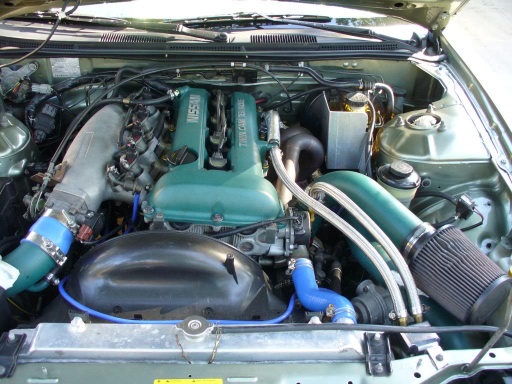
I'm trying to finish up installing the catch can on my turbo '97 LTX, but it looks like I've run out of vacuum ports so I can hookup the filtered clean air side.
As you can see, the only unutilized port is the stock PCV exit port (I have my catch can ran off an AN line added to the front of the driver's side valve cover). I did see a diagram where that port was used for the fresh air vacuum, but that didn't make sense to me as I'd think that port only flowed out, not providing vacuum in. Any thoughts on this?
As you can see, the only unutilized port is the stock PCV exit port (I have my catch can ran off an AN line added to the front of the driver's side valve cover). I did see a diagram where that port was used for the fresh air vacuum, but that didn't make sense to me as I'd think that port only flowed out, not providing vacuum in. Any thoughts on this?
TECH Addict
Joined: Dec 2010
Posts: 2,610
Likes: 4
From: Maricopa, AZ
The PCV port on the side of the intake is not a vacuum source, its a port to the lifter valley of the engine to evacuate the crankcase. The PCV port for vacuum is located under the throttle body.
Thread Starter
Launching!
Joined: Jul 2003
Posts: 258
Likes: 0
From: Rancho Cucamonga, CA
Yeah, that's what I thought and why that diagram I was shown didn't make sense to me. Unfortunately that port is already being used for the return line from the catch can.
So at this point, what are my options? Will I have to pull the intake and have another vacuum port drilled in? The only other port not being used is the EGR port at the back of the intake.
So at this point, what are my options? Will I have to pull the intake and have another vacuum port drilled in? The only other port not being used is the EGR port at the back of the intake.
It is inefficient, because the lines are so long, during boost there will not be enough pressure drop at the inlet to provide PCV action through such extensive plumbing. I recommend not using the catch can at all, unless your engine is bad/blowby is a problem.
This is what you want. This will keep boost and off-boost PCV action.

this is how PCV is routed on ALL OEM engines with boost. Combustion gasses are: gas state. They will not stop in the can / the catch can will not catch gas molecules / partially burnt hydrocarbons. Sure some might stick the walls of the tubes; but they would do that even without the can in place. The shorter the distance from the compressor inlet -> crank case the better your vacuum source during boost will be, the better the PCV action during WOT.
I was sent the same pic from mighty mouse. This is how he said I should run his pcv catch can for my NA setup:
remove all hoses
replace your pcv valve with restricted orifice
this now goes to your fresh air inlet at tb or etc.
run hose barb from valve cover to catch can inlet
catch can pcv outlet to intake manifold vac.�dum
thats it.
if we left the passenger v/c going to the throttle body you may still see oil consumption there.
I don't have my can yet but that's how I plan on installing it.
Trending Topics
LS1 Tech Stories
The Best V8 Stories One Small Block at Time

Topdon ONE vs. Artidiag 800 BT2: Which is the Diagnostic Tablet For You?
Pouria Savadkouei
Gas Monkey Built a 6-Wheel Ferrari Testarossa With a Corvette LT4 Engine
Verdad Gallardo
7 Most Reliable High-Performance Engines GM Has Ever Built
Verdad Gallardo
Amazing '71 Camaro Restomod Is Modern Muscle Car Under the Skin
Verdad Gallardo
6 Common C5 Corvette Failures and What's Involved In Repairing Them
Pouria Savadkouei
Retro Modern Bandit Pontiac Trans AM Comes With Burt Reynolds' Autograph
Verdad Gallardo
Top 10 Greatest Cadillac V Series Performance Models Ever, Ranked
Pouria Savadkouei
Top 10 Most Powerful Chevy Trucks Ever Made!

Hennessey's New Supercharged Silverado ZR2 Has 700 HP
Verdad Gallardo
with all due respect, i do not understand, all you did was draw a very colorful diagram of a stock system. how did that help the question?
the diagram linked has different routing on purpose
the diagram linked has different routing on purpose
It is inefficient, because the lines are so long, during boost there will not be enough pressure drop at the inlet to provide PCV action through such extensive plumbing. I recommend not using the catch can at all, unless your engine is bad/blowby is a problem.
This is what you want. This will keep boost and off-boost PCV action.

this is how PCV is routed on ALL OEM engines with boost. Combustion gasses are: gas state. They will not stop in the can / the catch can will not catch gas molecules / partially burnt hydrocarbons. Sure some might stick the walls of the tubes; but they would do that even without the can in place. The shorter the distance from the compressor inlet -> crank case the better your vacuum source during boost will be, the better the PCV action during WOT.
This is what you want. This will keep boost and off-boost PCV action.
this is how PCV is routed on ALL OEM engines with boost. Combustion gasses are: gas state. They will not stop in the can / the catch can will not catch gas molecules / partially burnt hydrocarbons. Sure some might stick the walls of the tubes; but they would do that even without the can in place. The shorter the distance from the compressor inlet -> crank case the better your vacuum source during boost will be, the better the PCV action during WOT.
Thread Starter
Launching!
Joined: Jul 2003
Posts: 258
Likes: 0
From: Rancho Cucamonga, CA
I spoke to Mr. Mouse and have everything figured out. I'm going to use my breather on the passenger valve cover for now that's routed to the suck side of the turbo intake, but I'll probably get a hollowed out PCV valve and stick a breather on that later.
I just didn't realize that the PCV exit location could be used for the fresh air inlet based on my assumption of how everything flowed, but I understand it will sere the purpose well. Now time to get it tuned soon!
BTW, I found an awesome location to mount the can. I'll try to get some pics before she goes.
Dear mr. Mouse,
Here is what I see in your diagram.
Lets consider boost situation. During boost, pressure in the crank case is > atmospheric, just like in a naturally aspirated engine during WOT, there is always some net blowby and thus the pressure there will always be higher than atmospheric.
Lets follow the red line now. Clearly this is an evacuation port for the crank case. i.e. there will be crankcase pressure here during WOT, boost or no boost, and it will enter the catch can. So far so good. Now, the outlet of the catch can (green) leads back to the manifold? It says green: "pcv return to manifold" so I am guessing that is the manifold. Well, during boost, the manifold pressure is higher than crank case pressure. So you will have NO pcv action during boost with the line like this.
Lets... tackle this first, before I go on to the other problems I see. Maybe I misunderstand what is going on here (I hope so)
- There is no manifold boost getting to the can, ever; and crank fumes are free to move from area of higher pressure (crank case) to area of lower pressure (intake or engine bay) whichever path is easier, 100% of the time.
I fail to understand, if the line is connected to the manifold, and boost pressure is 7psi, then it looks like there will be 7psi of boost in the catch can. The only way to stop that is with a PCV or "check" valve, which should not be installed there for other reasons. The line looks to be incorrectly labelled or else it is incorrectly utilized. Also, how is crankcase venting to the engine bay? that is a big problem on pcv systems in general, it unseals the crankcase (same as running an open filter)
PCV action is anywhere there is a pressure lower than crankcase pressure, that can also be applied to the crank case simultaneously. The only place to get that on a turbo car is from the pre-compressor inlet, which as you can see in the OEM design I posted, is tied directly the crank case.
Oh I see now there is an enormous filter on top of the can. So you are eliminating PCV all together and installing additional crank case volume with an atmospheric outlet. Not a good idea if that is the message. Also since the can is attached to the manifold, when the manifold sees vacuum, it will suck through the filter on the can, pulling in un-metered air to the manifold and none from the crank case (no PCV action). Is this what I am seeing correctly?
Last edited by kingtal0n; Feb 28, 2016 at 01:34 AM.
Why don't you start by asking questions and learn FIRST instead of talking about how wrong it is when you don't even know what is going on, (with all due respect).
Your approach is heavily affecting my answers.
Your approach is heavily affecting my answers.
Last edited by MIGHTYMOUSE; Feb 29, 2016 at 08:50 AM.
11 Second Club
Joined: Mar 2012
Posts: 1,541
Likes: 15
From: South Florida
Oh I see now there is an enormous filter on top of the can. So you are eliminating PCV all together and installing additional crank case volume with an atmospheric outlet. Not a good idea if that is the message. Also since the can is attached to the manifold, when the manifold sees vacuum, it will suck through the filter on the can, pulling in un-metered air to the manifold and none from the crank case (no PCV action). Is this what I am seeing correctly?
If you apply a vaccum to the can, it will pull air through the filter. It will not supply any vacuum to the crank case because there is an open filter on top.
Under boost you want pcv action, not a vent. Running an open filter is like putting breathers on the valve cover; it disables the PCV system completely. This leads to filthy oil, combustion by-product contaminated oil, the opposite of what you desire in a clean engine. It also assists in developing oil leaks at every oil seal. There is no benefit to an open filter. PCV systems when properly utilized also increase power output. By removing even the generic OEM pcv you are reducing oil quality AND lowering power output.
Under boost you want pcv action, not a vent. Running an open filter is like putting breathers on the valve cover; it disables the PCV system completely. This leads to filthy oil, combustion by-product contaminated oil, the opposite of what you desire in a clean engine. It also assists in developing oil leaks at every oil seal. There is no benefit to an open filter. PCV systems when properly utilized also increase power output. By removing even the generic OEM pcv you are reducing oil quality AND lowering power output.
This is the part where I love that picture above. Check it out one more time, please, Look at the compressor inlet pipe, the one attached to the air filter, and see how the inlet is feeding the crankcase fresh air under engine manifold vacuum? This is cruise situation. When you boost, the PCV valve shuts and flow reverses direction: it heads towards the inlet pipe, out of the crankcase, into the compressor. The oem often includes a healthy baffle in the valvecover (oil separation) and then sometimes convolutions in the inlet plumbing to control oil molecules which make it that far, they become trapped in a sort of healthy looking "sludge" over time between the convolutions, as an alternative on a problem engine (one with a poor baffle) THAT is when you resort to the catch can, when the oil quantity passing the valvecover baffles exceeds what you would feed the compressor wheel, and THAT is where you position the catch can to catch oil between. The popular (sr/2j) OEM Nissan and Toyota engines you see with 130,000 miles could use a degreasing and wash the compressor wheel (depends how crazy you get with maint.), but its never anything serious as long as the engine is healthy and they will go 200k+ without anyone even cleaning it once.
Here is a picture of how to route the catch can like in the picture above, like the OEM.
Ideally there is a gauge on can, or near it, to determine what sort of PCV action you are getting. Something in the inches of water range.
Here is a picture of how to route the catch can like in the picture above, like the OEM.

Ideally there is a gauge on can, or near it, to determine what sort of PCV action you are getting. Something in the inches of water range.
Last edited by kingtal0n; Feb 28, 2016 at 08:17 PM.
If you apply a vaccum to the can, it will pull air through the filter. It will not supply any vacuum to the crank case because there is an open filter on top.
Under boost you want pcv action, not a vent. Running an open filter is like putting breathers on the valve cover; it disables the PCV system completely. This leads to filthy oil, combustion by-product contaminated oil, the opposite of what you desire in a clean engine. It also assists in developing oil leaks at every oil seal. There is no benefit to an open filter. PCV systems when properly utilized also increase power output. By removing even the generic OEM pcv you are reducing oil quality AND lowering power output.
Under boost you want pcv action, not a vent. Running an open filter is like putting breathers on the valve cover; it disables the PCV system completely. This leads to filthy oil, combustion by-product contaminated oil, the opposite of what you desire in a clean engine. It also assists in developing oil leaks at every oil seal. There is no benefit to an open filter. PCV systems when properly utilized also increase power output. By removing even the generic OEM pcv you are reducing oil quality AND lowering power output.
11 Second Club
Joined: Mar 2012
Posts: 1,541
Likes: 15
From: South Florida
If you apply a vaccum to the can, it will pull air through the filter. It will not supply any vacuum to the crank case because there is an open filter on top.
Under boost you want pcv action, not a vent. Running an open filter is like putting breathers on the valve cover; it disables the PCV system completely. This leads to filthy oil, combustion by-product contaminated oil, the opposite of what you desire in a clean engine. It also assists in developing oil leaks at every oil seal. There is no benefit to an open filter. PCV systems when properly utilized also increase power output. By removing even the generic OEM pcv you are reducing oil quality AND lowering power output.
Under boost you want pcv action, not a vent. Running an open filter is like putting breathers on the valve cover; it disables the PCV system completely. This leads to filthy oil, combustion by-product contaminated oil, the opposite of what you desire in a clean engine. It also assists in developing oil leaks at every oil seal. There is no benefit to an open filter. PCV systems when properly utilized also increase power output. By removing even the generic OEM pcv you are reducing oil quality AND lowering power output.
I just went ahead & got a vacuum pump.
Last edited by SoFla01SSLookinstok; Feb 28, 2016 at 08:27 PM.