


Timing Pull Resistor Trick !
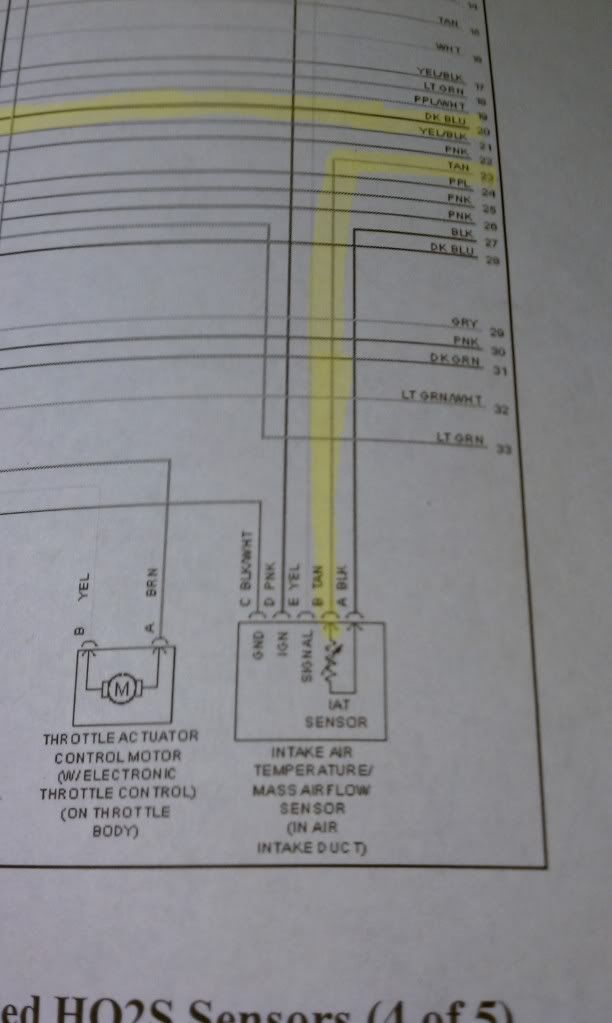
Bringing back from the dead, have a wiring diagram in front of me, I have no purple wire, Looks like black/white ground, yellow signal, pink ignition, tan IAT sensor, and black which is part of the IAT circuit which grounds in the pcm. Would I just exchange the purple wire in the diagram for the black attached to the IAT? it doesn't look like my IAT has a reference, just sensor and ground.

TECH Apprentice
Joined: Nov 2009
Posts: 367
Likes: 0
From: Kentucky
Bringing back from the dead, have a wiring diagram in front of me, I have no purple wire, Looks like black/white ground, yellow signal, pink ignition, tan IAT sensor, and black which is part of the IAT circuit which grounds in the pcm. Would I just exchange the purple wire in the diagram for the black attached to the IAT? it doesn't look like my IAT has a reference, just sensor and ground.
LS1 Tech Stories
The Best V8 Stories One Small Block at Time

Topdon ONE vs. Artidiag 800 BT2: Which is the Diagnostic Tablet For You?
Pouria Savadkouei
Gas Monkey Built a 6-Wheel Ferrari Testarossa With a Corvette LT4 Engine
Verdad Gallardo
7 Most Reliable High-Performance Engines GM Has Ever Built
Verdad Gallardo
Amazing '71 Camaro Restomod Is Modern Muscle Car Under the Skin
Verdad Gallardo
6 Common C5 Corvette Failures and What's Involved In Repairing Them
Pouria Savadkouei
Retro Modern Bandit Pontiac Trans AM Comes With Burt Reynolds' Autograph
Verdad Gallardo
Top 10 Greatest Cadillac V Series Performance Models Ever, Ranked
Pouria Savadkouei
Top 10 Most Powerful Chevy Trucks Ever Made!

Hennessey's New Supercharged Silverado ZR2 Has 700 HP
Verdad Gallardo what kinda resistor would you want to use to add timing instead of pulling it. I rather be on the safe side and run a nitrous tune, and when im n/a ill add timing. without looking at hp tuners and seeing at what time, how much voltage the knock sensor is picking up, if any, I wouldn't trust just pulling 3 degrees across the board on spray, as timing will vary during the hole shot. maybe im just confusing myself, but I want to do this and I want to get the greatest benefit while being safe, as im going to be running a 200 shot. I know this thread is also old as $#!+