


This will work, right? (Nitrous wiring questions)

Thread Starter
Teching In
Joined: Aug 2006
Posts: 29
Likes: 0
This will be going on my 2009 Pontiac G8 GT.
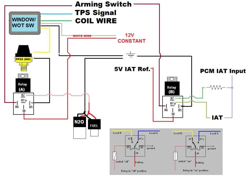
Been tossing this around in my head for a little bit, finally did an MS Paint diagram. I know it's not 100% perfect, but just want to make sure my logic is sound.
Main thing I'm thinking- I can use the 2'nd relay (RELAY B) to switch the 5v reference signal from the ECU? The coil is 100% independent of the switch on the relay, no? Last thing I wanna do is send 12 volts through my MAF and then ECU. Wouldn't be pretty, I don't think.
The fixed resistor will be whatever value I want to pull the desired about of timing (according to THIS HPTuners table) This resistor will only be used when the nitrous switch is armed. Whenever it isn't armed, it will revert back to the factory (relocated) IAT.
I'm using a Dynotune WOT / Window switch, which is designed to ground the signal wire when conditions (RPM and WOT Voltage) are met.
If you guys see anything that may not work, let me know.
your IAT resistor relay is wrong
you need it to switch the resistance,
30 should be the one the +signal wires(ohms) from the pcm, not the 5v reference.
87a should be the one wire of the IAT signal
87 should be one wire of the resistor.
both the resistor and the IAT other wire should just go to ground..(basically clip one side of the IAT signal wire and ground it to the chassis, same for resistor)
85 gets a ground
86 gets +12v arming
or vice versa...as long as one side of the coil is hot and the other side is ground
the key is that you are trying to switch from IAT resistance to fixed value resistance, so that resistance needs to pass thru the relay to the pcm.
Thread Starter
Teching In
Joined: Aug 2006
Posts: 29
Likes: 0
Trying to follow, don't really understand though. The 5v Reference is the 5V OUTPUT the ECU is sending to the factory IAT. Stock is like this:
ECU 5V OUT ---------- IAT ----------- 0-5v INPUT ECU
The way I have it diagrammed, I change it to this-
xxxxxxxxxxxxxxxxxxxxxxxxxxxxx IAT ----------------------
ECU 5V OUT -------- <xxxxxxxxxxxxxxxxxxxxxxxxxxxxxxxxx> 0-5v INPUT ECU
xxxxxxxxxxxxxxxxxxxxxxxxxxxxx RESISTOR ----------------
I don't see what grounding the IAT or Resistor will do for me.
I can be a bit dense, so please try and help me understand?
Thanks for input.
forgive me, I forgot its a 3 wire IAT
does it voltage back? or resistance to determine temperature...
if its voltage, the resistor mod is not going to work.
if its resistance...
then you still do it the way I mentioned...
leave the 5v out of it
also, if its voltage, then you need to know what the 0-5v represents...if 5 is high iat, then you can use your 5v...but not like you have it in your drawing
ok.. so a quick double check looks like its still resistance with the 3 wire..I could be wrong
some are voltage, some are resistance, dont know which ones get used in your vehicle.
so you will need to do it just like I mentioned above
IAT
+signal to 87A
-Signal to Chassis Ground or pcm(leave it uncut)
5v to pcm(leave it uncut
Resistor
+signal to 87
-signal to Chassis ground
30 will get the PCM side of the IAT sensor +signal
I'll try to draw something up to show you what I mean
Last edited by soundengineer; Dec 16, 2011 at 09:55 AM.
Thread Starter
Teching In
Joined: Aug 2006
Posts: 29
Likes: 0
That won't work. The ecu expects to see somewhere between 0 and 5 volts. The Iat is a variable resistor that will convert some of that voltage into heat. The fixed resistor does the same thing. The way you have it diagrammed, when using the fixed resistor, if checked with a voltmeter, the PCM would see 0 volts.
The ecu doesnt 'see' ohms or resistance, it sees voltage. It sends out 5 volts, puts it through a resistor, and gets back less than 5 volts. See ohms law.
If you could get a 2.5v dc power supply, and wire hat directly to the ecu's Iat signal input, it would read a certain temperature. Not sure what it'd be exactly, but the ecu would think is 69degrees or something,
Trending Topics
ok.. if its seeing voltage of 0-5vdc instead of ohms,
then just substitute...
the ohms value will be a voltage value...
same thing goes on....
the resistor side now just needs to be a 5v source coming into 87
you could either use an existing 5v source(which could cause a dirty signal)
or you could go buy a voltage regulator (5v, 3 prong, accepts up to 35vdc) from Radio Shack..
then just take any 12v switched source(like the one you use for your relay pin 85) and you can hit the regulator, and it will output 5v
then you just need to edit the tune so that the IAT it represents pulls timing for nitrous.
LS1 Tech Stories
The Best V8 Stories One Small Block at Time

Gas Monkey Built a 6-Wheel Ferrari Testarossa With a Corvette LT4 Engine
Verdad Gallardo
7 Most Reliable High-Performance Engines GM Has Ever Built
Verdad Gallardo
Amazing '71 Camaro Restomod Is Modern Muscle Car Under the Skin
Verdad Gallardo
6 Common C5 Corvette Failures and What's Involved In Repairing Them
Pouria Savadkouei
Retro Modern Bandit Pontiac Trans AM Comes With Burt Reynolds' Autograph
Verdad Gallardo
Top 10 Greatest Cadillac V Series Performance Models Ever, Ranked
Pouria Savadkouei
Top 10 Most Powerful Chevy Trucks Ever Made!

Hennessey's New Supercharged Silverado ZR2 Has 700 HP
Verdad Gallardo