

HOW TO: Make a Timing Retard Box for a Nitrous Oxide system...

Still all in all, everybody who talks about how cheap this is to do, don't ever include the cost of buying HPT or EFI live. You have to think about the guy who has nothing at all and is starting from scratch. Which route do you think he is going to go?
The only good thing I see from this is having multi stage retard for multiple shots.
The only good thing I see from this is having multi stage retard for multiple shots.
Ugh......Re-read the last part of my original HOW TO: post. You will notice that I mention there being an alternate option for those who don't have access to HPT, EFILive or other tuning solution. Look in the G8 IAT Spark Tables and you will see that it also pulls -3* spark at 113*F and pulls -5* at 122*F. The Multiplier table for these corresponding cells requests roughly about 75% across the RPM range which means -2.25* spark being pulled for the -3* figure in the main IAT Spark Table and 3.75* timing being pulled for the -5* figure in the main IAT Spark Table. So as long as you can get someone to send you the screen shots of what your vehicle's tune looks like in this area then you will have all of the information to be able to make the box according to what temperature cell you need to reference and also what resistance equates to that from the IATS. That would be a way to accomplish this, although not as cleanly in my book, without ever changing the existing tune in the vehicle.
Besides, you don't have to own HPT or EFILive to do this in the tune. Chances are likely that if you are spraying nitrous that you also have some boltons. This means that you should already have a N/A tune. When you have your tuner finalizing your N/A tune you can show them this thread with the above screenshots and request that they take the 3 minutes to change these settings to whatever you prefer. So 3 minutes x roughly $100/hr labor charge equates to roughly $5. Not exactly breaking the bank is it.
I didn't really think I had to lay it out this far for the skeptics. Use your own creativity and there are many options you can have with this item based on what capabilities and tools you do or don't have.

If you do the rheostat,potentiometer, or anything else you still want to have it activate into the IATS circuit by some sort of switch and relay, whether that be the master arm or other, so that when you are normally driving then the ECM is still able to pull unmodified data from the IATS itself.


id buy one for $50 bucks.im about to get my car tuned after my plate kit install and my tuner asked me if i wanted and n/a tune or a nitrous tune.i guess imma gonna get the nitrous tune. but with this device i am assuming i could run maximum timing advance and then when im at the track i could retard the timing 4* or so and be safe,rather than running around town 4* retarded all the time.
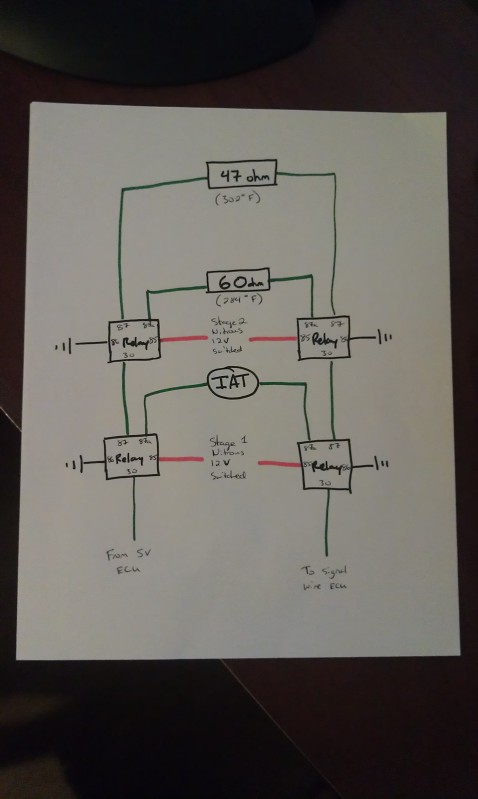
If trying to wire up different amounts of timing pulled for two different stages of nitrous, would this wiring work?
I understand that the timing tables need to be adjusted via HPTuners.
I got the ohm numbers from this post: https://ls1tech.com/forums/12990137-post2.html
I understand that the timing tables need to be adjusted via HPTuners.
I got the ohm numbers from this post: https://ls1tech.com/forums/12990137-post2.html
If trying to wire up different amounts of timing pulled for two different stages of nitrous, would this wiring work?

I understand that the timing tables need to be adjusted via HPTuners.
I got the ohm numbers from this post: https://ls1tech.com/forums/12990137-post2.html
I understand that the timing tables need to be adjusted via HPTuners.
I got the ohm numbers from this post: https://ls1tech.com/forums/12990137-post2.html
You got it. Good job on the diagram. Just make sure that you test your actual ohms of resistance since resistors are rated for a range of accuracy of resistance. A 100k resistor may actually resist only 95k or so on. Then since you have HPT datalog your "IAT" with the switches in their various stages to ensure that your ECM is seeing what it should so that you know it will be using the corresponding column of the IAT spark tables. It looks like you are well on your way.

Just want to say thanks for the write up appreciate the time it took you. Just got hp tuners and installing nitrous on the car as we speek big help. Sticky material alot of people new to nitrous have probably never seen this
What would be a nice addition is a multiple input so more than one stage can be used. IE fixed resistance for each system once armed.
Arm stage one, have it pull say 3* in temp cells -4
Arm stage two and have it pull say 8* in temp cells -40
This would work better in my application where I won't be on both stages out of the hole.
Arm stage one, have it pull say 3* in temp cells -4
Arm stage two and have it pull say 8* in temp cells -40
This would work better in my application where I won't be on both stages out of the hole.

Sorry for the late reply! Been getting divorced and ****. lol.
Chances are likely that you will have a digital multimeter when doing the wiring for this project. Set it to test ohms of resistance Ω and then verify what actual resistance you get out of your resistors. Remember, that just like anything else in life there is a standard deviation that the resistors are rated to, within the area of their claimed resistance. So even though you buy a 100k ohm resistor and it has a +/- 3% rating, you may probe its actual resistance and discover is only has 97k ohms of resistance or something else within 3% above or below the rated amount. Just make sure to meet or exceed the resistance value of the cell of the spark table you are working in so that you know you will be referencing the correct table to pull the amount of timing you want to pull. It would suck to assume that the car is pulling 4 degrees of spark when it is actually only pulling 2 because actual resistance of your home-built resistor pack didn't add up to enough to hit whatever IAT spark cell column you are trying to hit. If you really want to be sure then a quick 20 second datalog will do the trick to verify everything reads kosher.
Chances are likely that you will have a digital multimeter when doing the wiring for this project. Set it to test ohms of resistance Ω and then verify what actual resistance you get out of your resistors. Remember, that just like anything else in life there is a standard deviation that the resistors are rated to, within the area of their claimed resistance. So even though you buy a 100k ohm resistor and it has a +/- 3% rating, you may probe its actual resistance and discover is only has 97k ohms of resistance or something else within 3% above or below the rated amount. Just make sure to meet or exceed the resistance value of the cell of the spark table you are working in so that you know you will be referencing the correct table to pull the amount of timing you want to pull. It would suck to assume that the car is pulling 4 degrees of spark when it is actually only pulling 2 because actual resistance of your home-built resistor pack didn't add up to enough to hit whatever IAT spark cell column you are trying to hit. If you really want to be sure then a quick 20 second datalog will do the trick to verify everything reads kosher.
Last edited by rocket5979; Dec 6, 2012 at 11:37 PM.
Sorry about thethe big D, been thereyou done that. Thanks for the reply, i was unsure so i drove to a hobby shop about 30 miles away and got the right one. The box is done and on and is pulling the timing perfectly. Thanks for the write up!
I am glad to hear this thread is helping people.
this may be a little old, but you do realize you guys are over complicating this right? the box and resistor etc are not necessary. if the IAT (or ECT whichever you choose) circuit is broken, the PCM defaults out to the max coldest value (-40 IAT, -38 ECT). you cna just hook up a 5 pole relay with the singal wire going to the load in wire and the normally closed contact. then trigger the relay off your WOT switch to break the circuit and deafault it to the -40 table, and do your nitrous tune on the -40 IAT table like you showed. same results, just simpler way of going about it. I accidentally discovered this when dealing with wiring issues on my 5.3 swap
this may be a little old, but you do realize you guys are over complicating this right? the box and resistor etc are not necessary. if the IAT (or ECT whichever you choose) circuit is broken, the PCM defaults out to the max coldest value (-40 IAT, -38 ECT). you cna just hook up a 5 pole relay with the singal wire going to the load in wire and the normally closed contact. then trigger the relay off your WOT switch to break the circuit and deafault it to the -40 table, and do your nitrous tune on the -40 IAT table like you showed. same results, just simpler way of going about it. I accidentally discovered this when dealing with wiring issues on my 5.3 swap
There is more than one way to skin a cat; and your reservations about the methodry for this mod have already been answered in detail previously in this thread. Whether you use the more complicated method, outlined in this thread, or not completely depends on how you want to set your spark timing retard. This especially holds true for multistage nitrous equipped cars where you may prefer to have different spark retardation settings for each stage. So, in short, no my method is not "too complicated" depending on the application.