

HOW TO: Make a Timing Retard Box for a Nitrous Oxide system...


Mine is similar to this without the box, but mounted in the spare change console next to my nitrous switch panel. Since the mishap I've had 4 yrs ago, my previous tuner re-wired it so the nitrous will not come on unless the switch is flipped on. 
That is the way I setup all of the nitrous systems that I install too. I always wire it so that the safeties are wired in a way so that the user cannot activate anything without those first being active. In most cases that means a single switch controlling them all, unless the owner is real adamant about maintaining separate switches for reason of preference. There are just too many people who get in the heat of the moment, excited about a big race, etc; and forget to flip a switch.

TECH Enthusiast
Joined: Nov 2006
Posts: 620
Likes: 0
From: Katherine N.T Australia
Problem with hacking the IAT sensor to use the IAT/Spark table is IAT is also a function of the air flow model and thus effects fuelling. ie you'll effectively loose any influence to control fuelling in varying ambient temp's when on the juice.
This has already been addressed in this thread, as well as other threads, by those of us who have been tuning GMs and Fords for a long time.
It is a non-issue as long as you are only engaging the IAT signal modifier while using the spray and thus more or less at WOT for the entire time (aka in Open loop PE fueling mode, not closed loop fueling, as well). The car will be dumping more fuel in during PE to achieve a richer AFR and since we are tricking the car into thinking that the aircharge is colder, and thus more dense, the computer will be trying to add more fuel as well. So, since I always advocate a nitrous tune to take the most advantage of things then less additional fuel can be demanded via PE so that WOT AFR's don't drift too rich while making the pass on the track. At the very least, at least the AFR's if left unchecked by someone too lazy or cheap to make a nitrous specific tune will drift more rich and not leaner as the IAT mod is engaged. Keep in mind that this will be different if the IAT is tricked to read on the high temp side of the range, which I do not recommend if avoidable.
Teching In
Joined: Dec 2012
Posts: 25
Likes: 0
From: Florida
Rocket, I think you did a great job with this thread, thank you. I ran across it while looking for how others wire these relays.
I used a single relay, activated by the master arming switch. 85 and 86 go to ground and the arming switch, as usual. The original IAT sensor wire was cut in half near the sensor itself, and the two ends go to the relay on pins 30 and 87a, maintaining the original IAT sensor path. Pin 87 (the connection that gets used when the system is armed) remained unconnected to anything. This caused the IATs to drop to -40F when the system was armed, by basically breaking the IAT sensor wire.
The problem is that the car doesn't pull any timing. So I checked the tune, and found that -5 degrees was being pulled in the IAT table anywhere below +5 degrees F. Next, I looked at the IAT mult 2 table (IAT vs coolant temp), and found that it was set to 0, up til 122 degrees, .5 at 140 degrees, and 1.0 from 158 up. This causes alarm, because what happens if some nimrod hits the juice at 140 degrees or below? I am assuming the way this table works is by multiplying the original IAT table, so -5 x 0 = 0. No timing pulled! So that table might need to get dragged down a little further to be safe. Perhaps set to 1.0 from 122 or 140 degrees on up.
But this was not my problem anyway. I was at normal operating temperature, so my multiplier is 1.0. The car should be pulling 5 degrees.
So I looked at the mult 1 table (IAT vs RPM) and found that it varied a lot, but basically everything below 104 IAT had a multiplier of 0, and everything above 104 varied between .75 and 1.0. This would cause timing to pull between 3.75 and 5 degrees, depending on RPM if the IAT read above 104. But since the IAT mod would register -40, the multiplier would be 0, and no timing would be pulled. So I changed all the lower temp settings to 1.0, so when the IAT reads -40, the full 5 degrees would be pulled (-5 x 1.0 = -5).
And to my surprise, NOTHING. No timing being pulled. I logged all the timing and retard parameters there was, and nothing. So I have a theory... maybe when you trick the IAT into reading the full -40F, the car goes into (what Ford calls FMEM) a sensor failure management mode, and doesn't pull anything. Has anybody else encountered this??
Moral of story is to make sure you datalog the IAT and the actual final timing advance value, to make SURE your car actually pulls the timing.
I'm off to Radio Shack now, to grab some resistors, a 0-100,000 ohm potentiometer, and I am going to test this theory by temporarily wiring the potentiometer inline to the IAT. If all goes well, I can use the potentiometer to find the exact amount of resistance I need (which I already know anyway, but I want to see it work and see if my FMEM theory is correct). I will then wire in the appropriate amount of resistors inline between Pin 87 and a ground.
If I remember right, you add up resistor values to get a total resistance value, right? Like a 3k and a 2K resistor in series will = a 5k resistor, right? Looks like I'm going to want around 23,000 ohms to hit 0 degrees in my table.

The tan and purple wires are for the IAT, other 3 are for the MAF in the 5 wire setups. Same as the separate units, just combined in one connector

Registered User
Joined: Sep 2013
Posts: 2
Likes: 0
You have 5 slots A-E, A being low reference (tan), B being IATS signal (tan), C being MAF signal (yellow), D being Battery positive (Pink/Black), and E being chassis ground (black)
Just want to be sure im wiring correctly because it would be nice having full power until nitrous is armed. I built the box to the exact instructions and im just alittle unsure on how its wired in and which wire will correspond with which to make it function properly, sorry for the newb question just wanna be sure its done properly. Mine main concern is not interfering with the MAF the low refrence which im assuming is a sensor ground idk if they share this and if it will affect anything
Last edited by TwoToneTerror; Sep 9, 2013 at 08:56 PM.
On The Tree
Joined: Jun 2012
Posts: 122
Likes: 2
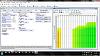
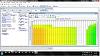
What would someone do with a truck OS that only goes down to 14f IAT Spark - Base. Here have a look .. I did think about using the ECT though not sure how that would affect other portions of the tune like fueling and what not.. help I WANT NITROUS  BAD
BAD
BAD 

Last edited by the404man; Nov 27, 2013 at 02:31 AM.

Registered User
Joined: Dec 2014
Posts: 16
Likes: 0
From: Largo, FL
Rocket, I think you did a great job with this thread, thank you. I ran across it while looking for how others wire these relays.
I used a single relay, activated by the master arming switch. 85 and 86 go to ground and the arming switch, as usual. The original IAT sensor wire was cut in half near the sensor itself, and the two ends go to the relay on pins 30 and 87a, maintaining the original IAT sensor path. Pin 87 (the connection that gets used when the system is armed) remained unconnected to anything. This caused the IATs to drop to -40F when the system was armed, by basically breaking the IAT sensor wire.
The problem is that the car doesn't pull any timing. So I checked the tune, and found that -5 degrees was being pulled in the IAT table anywhere below +5 degrees F. Next, I looked at the IAT mult 2 table (IAT vs coolant temp), and found that it was set to 0, up til 122 degrees, .5 at 140 degrees, and 1.0 from 158 up. This causes alarm, because what happens if some nimrod hits the juice at 140 degrees or below? I am assuming the way this table works is by multiplying the original IAT table, so -5 x 0 = 0. No timing pulled! So that table might need to get dragged down a little further to be safe. Perhaps set to 1.0 from 122 or 140 degrees on up.
But this was not my problem anyway. I was at normal operating temperature, so my multiplier is 1.0. The car should be pulling 5 degrees.
So I looked at the mult 1 table (IAT vs RPM) and found that it varied a lot, but basically everything below 104 IAT had a multiplier of 0, and everything above 104 varied between .75 and 1.0. This would cause timing to pull between 3.75 and 5 degrees, depending on RPM if the IAT read above 104. But since the IAT mod would register -40, the multiplier would be 0, and no timing would be pulled. So I changed all the lower temp settings to 1.0, so when the IAT reads -40, the full 5 degrees would be pulled (-5 x 1.0 = -5).
And to my surprise, NOTHING. No timing being pulled. I logged all the timing and retard parameters there was, and nothing. So I have a theory... maybe when you trick the IAT into reading the full -40F, the car goes into (what Ford calls FMEM) a sensor failure management mode, and doesn't pull anything. Has anybody else encountered this??
Moral of story is to make sure you datalog the IAT and the actual final timing advance value, to make SURE your car actually pulls the timing.
I'm off to Radio Shack now, to grab some resistors, a 0-100,000 ohm potentiometer, and I am going to test this theory by temporarily wiring the potentiometer inline to the IAT. If all goes well, I can use the potentiometer to find the exact amount of resistance I need (which I already know anyway, but I want to see it work and see if my FMEM theory is correct). I will then wire in the appropriate amount of resistors inline between Pin 87 and a ground.
If I remember right, you add up resistor values to get a total resistance value, right? Like a 3k and a 2K resistor in series will = a 5k resistor, right? Looks like I'm going to want around 23,000 ohms to hit 0 degrees in my table.
I used a single relay, activated by the master arming switch. 85 and 86 go to ground and the arming switch, as usual. The original IAT sensor wire was cut in half near the sensor itself, and the two ends go to the relay on pins 30 and 87a, maintaining the original IAT sensor path. Pin 87 (the connection that gets used when the system is armed) remained unconnected to anything. This caused the IATs to drop to -40F when the system was armed, by basically breaking the IAT sensor wire.
The problem is that the car doesn't pull any timing. So I checked the tune, and found that -5 degrees was being pulled in the IAT table anywhere below +5 degrees F. Next, I looked at the IAT mult 2 table (IAT vs coolant temp), and found that it was set to 0, up til 122 degrees, .5 at 140 degrees, and 1.0 from 158 up. This causes alarm, because what happens if some nimrod hits the juice at 140 degrees or below? I am assuming the way this table works is by multiplying the original IAT table, so -5 x 0 = 0. No timing pulled! So that table might need to get dragged down a little further to be safe. Perhaps set to 1.0 from 122 or 140 degrees on up.
But this was not my problem anyway. I was at normal operating temperature, so my multiplier is 1.0. The car should be pulling 5 degrees.
So I looked at the mult 1 table (IAT vs RPM) and found that it varied a lot, but basically everything below 104 IAT had a multiplier of 0, and everything above 104 varied between .75 and 1.0. This would cause timing to pull between 3.75 and 5 degrees, depending on RPM if the IAT read above 104. But since the IAT mod would register -40, the multiplier would be 0, and no timing would be pulled. So I changed all the lower temp settings to 1.0, so when the IAT reads -40, the full 5 degrees would be pulled (-5 x 1.0 = -5).
And to my surprise, NOTHING. No timing being pulled. I logged all the timing and retard parameters there was, and nothing. So I have a theory... maybe when you trick the IAT into reading the full -40F, the car goes into (what Ford calls FMEM) a sensor failure management mode, and doesn't pull anything. Has anybody else encountered this??
Moral of story is to make sure you datalog the IAT and the actual final timing advance value, to make SURE your car actually pulls the timing.
I'm off to Radio Shack now, to grab some resistors, a 0-100,000 ohm potentiometer, and I am going to test this theory by temporarily wiring the potentiometer inline to the IAT. If all goes well, I can use the potentiometer to find the exact amount of resistance I need (which I already know anyway, but I want to see it work and see if my FMEM theory is correct). I will then wire in the appropriate amount of resistors inline between Pin 87 and a ground.
If I remember right, you add up resistor values to get a total resistance value, right? Like a 3k and a 2K resistor in series will = a 5k resistor, right? Looks like I'm going to want around 23,000 ohms to hit 0 degrees in my table.
Wow, it's been a long time since I have been in here. I haven't received any updates that new posts were in the thread until now.
In short, not all GM cars will have the exact same tables, settings, and multipliers for how their ECU retards spark timing in reference to IAT. This difference becomes even more pronounced when you apply this methodry to Ford ECU logic. The best info I can provide here is to keep looking at the tables to see what direction the logic that controls IAT spark travels in. I know that this is VERY vague, but that is the most specific I can get without literally taking a look at everyone's tunefiles to see what logic/architecture was used to approach controlling IAT spark with their specific ECU and OS.
As pontisteve mentioned, doing a datalog to verify that these hardware, and corresponding software, changes made actually net your desired result is highly adviseable. Even if I am "100%" sure about a change I made in a tune, I always verify that it had the effect that I was seeking via datalogs. Whether that be datalogging on your own, or if you pay your tuner to do so is up to your preference.
Registered User
Joined: Dec 2014
Posts: 16
Likes: 0
From: Largo, FL
I sent Pontisteve a pm and got a really great reply back. I think my resistor is too high putting my voltage too high. The car got a code for IAT sensor voltage too high. It must think the sensor failed so it's not pulling any timing. I'm going to get some different resistors and bring the IAT down to -20 or so instead of -40 and see how it goes
Teching In
Joined: Dec 2012
Posts: 25
Likes: 0
From: Florida
Normally, I might keep this card a little closer to my chest, but today I'm going to spill the beans. So go on over to Facebook and click LIKE on Drag Radial Performance's page for me! www.facebook.com/dragradialperformance. There's also a ton of tech articles over there you might enjoy. Here goes.
I wasn't using any timing retard box. The car was just using a relay (turned on by the nitrous button). The relay caused the IAT signal to go through a resistor.
In the case of the GTO I was working on, no timing was getting pulled, and the car was built by some other jackass. My job was to figure out why. I found 3 things wrong total.
1) There was a multiplier table in the softare that multiplied the timing retard amount by this table. I forget what the table was based on, but it had all zero's in it. So it was multiplying the 5 degrees that should have been pulled by zero. 5 x 0 = 0. So no timing was pulled. Chalk that up to the previous tuner missing that.
2) And this is the big one. They didn't use a resistor. They simply grounded (as I recall) the IAT signal wire. This causes the PCM to read -40 IAT. Any time you get too close to the very ends of the signal range (-40 or +256 in this case), you are into an area where the PCM realizes that this is likely an error. I don't know the exact cutoff in GM's, but let's just say it's something like -30 to +246, for example. Anything within that range is normal. Anything outside that range is too close to the ends of the sensor range, and the PCM knows that isn't right.
In the world of Fords, this happens on 0 to 5 volt sensors when you get below about .2 volts, or above about 4.8 volts. Same concept... too close to the end of the range to be believable, so the car goes into what Ford calls a Failed Memory Effects Management mode. In this mode, Ford substitutes a predetermined value in there, and ignores the sensor. So for example, if your coolant temp sensor goes bad, Ford knows that by seeing the voltage on the sensor signal being too close to 0 or 5, and goes into FMEM, then substitutes 180 degrees as a coolant reading.
GM works differently, as I found out. GM uses the last believable value it saw before the sensor took a crap. So when I was reading a normal say 80 degrees IAT, and then activated this nitrous IAT mod, the IAT sensor went from reading 80 to reading -40. The PCM picked up on the fact that -40 is too cold to believe, and therefore just kept using 80 as a substituted value. I can't remember if you can see this happening, but that's what is happening. And how much timing is being pulled out at 80 degrees? None. At least not in my tune.
The fix for this is to use a resistor, and not hook the sensor signal wire straight to ground. A small amount of resistance will cause the sensor to read -20 or something, instead of -40. This is enough for the PCM to believe the reading, and look at the IAT timing retard table. It's also low enough of a reading that there's no way this car would ever actually be used in that climate, so it was safe for me to pull timing out down in that -40 to 0 degree IAT range without fearing the car would ever actually see that range.
3) Once I fixed these two things, the car would pull timing when I hit the nitrous button. But it wasn't pulling the right amount of timing for the temperature row I was in, in the software. This confused me, but after enough trial and error, I realized that HP Tuners had the breakpoints wrong on the table. I figured out what they should have been, and notified HP Tuners and they fixed it the same day. Probably did it so fast because the next day they were releasing version 2.24 and wanted it to be right.
In order to figure out what resistor to use, I built a little box at Radio Shack with a potentiometer in it that varied resistance. I hooked the box up inline to the IAT signal wire, and that allowed me to turn the **** and change the IAT readings. Once I dialed it to the IAT that I wanted (somewhere around -20 to -30 degrees as I recall), I unplugged the box and measured the resistance of it with an ohmmeter. Then I bought a resistor from Radio Shack that had the same amount of resistance. Worked like a charm.
The magic number on that particular GTO (and quite possibly all GM cars)?
56,000 ohms.
The right resistor would have a Green / Blue / Orange / Gold stripe.
Green means 5. Blue means 6. Orange means x 1,000. And Gold means this resistor's tolerance is 5% (high quality).
When I tested this resistor in the car, I think the temperature range was something between 0 and -30 degrees. That's low enough to be in the range where you'll never really drive the car in that weather, and not so low that you will hit the diagnostic range of the sensor voltage, making the PCM think the sensor is bad and ignoring it.
You would use a typical Bosch 5 wire relay. The 87 and 87A terminals will both be used. The IAT sensor signal wire would travel through terminal 30 to the normally closed terminal (87A) when the kit is off. When you turn the master arm switch on, the relay should be activated and the IAT sensor signal wire would now travel through relay terminal (87) instead.
Next, hook terminal 87 to a verified good ground, with the 56k resistor inline with that wire somewhere. This way, when you turn the master arm switch on, power from that switch goes to activate the IAT mod relay. This will pull timing immediately if everything is working, so datalog the car and verify that when you turn on the master arm switch, x amount of timing is pulled instantly and globally.
I choose to retard the timing globally as soon as you hit the master arm switch, instead of using the instant on nitrous activation button, for two reasons. One, you can instantly hear the engine change pitch, and that will be your confirmation that the retard is working right, without resorting to datalogging all the time. (The first time you do this, you should be datalogging to confirm!). And two, I want that retard to already be in place when I hit the nitrous button, so there is no delayed reaction. I don't want the nitrous to activate, and a small amount of time later, the timing retards. This is probably just being overcautious.
Originally Posted by tmenees2
Did you ever figure out the issue with the timing retard box not pulling timing? I know its an old thread but i just found it and decided to try it and ended up with the same thing. The IAT goes to -40 like it should but on the log its not pulling any timing. Just curious if you continued with it or not
In the case of the GTO I was working on, no timing was getting pulled, and the car was built by some other jackass. My job was to figure out why. I found 3 things wrong total.
1) There was a multiplier table in the softare that multiplied the timing retard amount by this table. I forget what the table was based on, but it had all zero's in it. So it was multiplying the 5 degrees that should have been pulled by zero. 5 x 0 = 0. So no timing was pulled. Chalk that up to the previous tuner missing that.
2) And this is the big one. They didn't use a resistor. They simply grounded (as I recall) the IAT signal wire. This causes the PCM to read -40 IAT. Any time you get too close to the very ends of the signal range (-40 or +256 in this case), you are into an area where the PCM realizes that this is likely an error. I don't know the exact cutoff in GM's, but let's just say it's something like -30 to +246, for example. Anything within that range is normal. Anything outside that range is too close to the ends of the sensor range, and the PCM knows that isn't right.
In the world of Fords, this happens on 0 to 5 volt sensors when you get below about .2 volts, or above about 4.8 volts. Same concept... too close to the end of the range to be believable, so the car goes into what Ford calls a Failed Memory Effects Management mode. In this mode, Ford substitutes a predetermined value in there, and ignores the sensor. So for example, if your coolant temp sensor goes bad, Ford knows that by seeing the voltage on the sensor signal being too close to 0 or 5, and goes into FMEM, then substitutes 180 degrees as a coolant reading.
GM works differently, as I found out. GM uses the last believable value it saw before the sensor took a crap. So when I was reading a normal say 80 degrees IAT, and then activated this nitrous IAT mod, the IAT sensor went from reading 80 to reading -40. The PCM picked up on the fact that -40 is too cold to believe, and therefore just kept using 80 as a substituted value. I can't remember if you can see this happening, but that's what is happening. And how much timing is being pulled out at 80 degrees? None. At least not in my tune.
The fix for this is to use a resistor, and not hook the sensor signal wire straight to ground. A small amount of resistance will cause the sensor to read -20 or something, instead of -40. This is enough for the PCM to believe the reading, and look at the IAT timing retard table. It's also low enough of a reading that there's no way this car would ever actually be used in that climate, so it was safe for me to pull timing out down in that -40 to 0 degree IAT range without fearing the car would ever actually see that range.
3) Once I fixed these two things, the car would pull timing when I hit the nitrous button. But it wasn't pulling the right amount of timing for the temperature row I was in, in the software. This confused me, but after enough trial and error, I realized that HP Tuners had the breakpoints wrong on the table. I figured out what they should have been, and notified HP Tuners and they fixed it the same day. Probably did it so fast because the next day they were releasing version 2.24 and wanted it to be right.
In order to figure out what resistor to use, I built a little box at Radio Shack with a potentiometer in it that varied resistance. I hooked the box up inline to the IAT signal wire, and that allowed me to turn the **** and change the IAT readings. Once I dialed it to the IAT that I wanted (somewhere around -20 to -30 degrees as I recall), I unplugged the box and measured the resistance of it with an ohmmeter. Then I bought a resistor from Radio Shack that had the same amount of resistance. Worked like a charm.
The magic number on that particular GTO (and quite possibly all GM cars)?
56,000 ohms.
The right resistor would have a Green / Blue / Orange / Gold stripe.
Green means 5. Blue means 6. Orange means x 1,000. And Gold means this resistor's tolerance is 5% (high quality).
When I tested this resistor in the car, I think the temperature range was something between 0 and -30 degrees. That's low enough to be in the range where you'll never really drive the car in that weather, and not so low that you will hit the diagnostic range of the sensor voltage, making the PCM think the sensor is bad and ignoring it.
You would use a typical Bosch 5 wire relay. The 87 and 87A terminals will both be used. The IAT sensor signal wire would travel through terminal 30 to the normally closed terminal (87A) when the kit is off. When you turn the master arm switch on, the relay should be activated and the IAT sensor signal wire would now travel through relay terminal (87) instead.
Next, hook terminal 87 to a verified good ground, with the 56k resistor inline with that wire somewhere. This way, when you turn the master arm switch on, power from that switch goes to activate the IAT mod relay. This will pull timing immediately if everything is working, so datalog the car and verify that when you turn on the master arm switch, x amount of timing is pulled instantly and globally.
I choose to retard the timing globally as soon as you hit the master arm switch, instead of using the instant on nitrous activation button, for two reasons. One, you can instantly hear the engine change pitch, and that will be your confirmation that the retard is working right, without resorting to datalogging all the time. (The first time you do this, you should be datalogging to confirm!). And two, I want that retard to already be in place when I hit the nitrous button, so there is no delayed reaction. I don't want the nitrous to activate, and a small amount of time later, the timing retards. This is probably just being overcautious.
Registered User
Joined: Dec 2014
Posts: 16
Likes: 0
From: Largo, FL
So it took me all day to finally figure it out but I'm making progress. I had it setup wrong and didn't see this last post until after I figured it out. I didn't know I needed to put a ground on the resistor attached to the signal wire. But I have the IAT reading -26 degrees now. I just have to setup the timing tables now. Hopefully tomorrow I'll get it finished up. But I'll let you know the outcome. It really needs this to work. It's not an LS but this is the only place I found a good thread about how to build one. It's going on a 2013 Cadillac ATS 3.6L. I have an Hp Tuner with a 2 stage 150 shot on it. I have to pull a lot of timing in the tune to keep the knock down. Motor is 11.5:1 compression stock so it fights me. Not much fun to drive with that much timing pulled so hopefully I get it worked out. I ran an 11.62@116mph last weekend. So it runs pretty good for a V6 four door Cadillac :-) I really appreciate all the help and input
Teching In
Joined: Dec 2012
Posts: 25
Likes: 0
From: Florida
You may want to consider the things that are causing heat, and try to knock them down some so the motor is more timing tolerant. Also, fuel makes a pretty good combustion chamber temp cooler.
The IAT retard relay basically splits the IAT signal off into two different directions. The normally closed contact (87A) connects the IAT signal wire back together. The normally open contact (87) connects the IAT signal wire to the resistor. The resistor then goes off to ground. You just solder the resistor inline, heat shrink it, and forget it, and then connect that wire to a real good ground. Real good ground!
When the relay is off, 87A keeps the system working as if the relay didn't exist. With the relay on, the signal wire is diverted to ground, but the resistor inline keeps the 5v signal coming from the PCM from being pulled all the way down to ground. Instead, because of the resistor, it pulls it only most of the way to ground.
Make sure that when you throw the master arm switch, you instantly see (and hear) the timing being pulled out of the motor. And log the timing, to see that it does indeed drop as much as you commanded it to!!!!!
You might want to use the bi-directional controls in the HP Tuners Scanner to lock the timing at a fixed amount, or just hold the throttle at say 1500 RPM where the timing is steady. Then arm the switch, and watch that instant timing drop. What am I saying.... just log IAT Retard, and you'll see it go from 0 to 5, or however many degrees of timing you are pulling.
Hey, don't forget that nitrous requires extra fuel. Whether you add that with the kit, or add that with the EFI.
Registered User
Joined: Dec 2014
Posts: 16
Likes: 0
From: Largo, FL
So its finally complete! It took me a while to get it figured out and installed. I used a single 5 pole relay with 2 resistors totaling 27k ohms. 27k brought the IAT to -26 degrees. The car didnt like going to -40 degrees. It kept thinking the sensor had failed and would get a code for IAT sensor voltage too high and not pull the timing. I just ran the n2o and it worked perfect. I data logged without the n2o for a while switching it on and off verifying that it was going to pull timing everytime like it is supposed to which it did. So I started with the 1 stage today wich is an 80 shot. Had a little knock so I pulled a little more timing, made a couple fuel adjustments and it was right on. Then I added the second stage. After the inital adjustments on the 1st stage the second stage was perfect. So I finally have the car back together with both stages running on the retard box. Im really excited to have the car running good on the motor again. I end up pulling about 15 degrees of timing for the 155 shot. Stock WOT is about 27 degrees advance. The car seems to like about 12-14 degrees advance with AFR of 11.2 on E85 with the 155 shot. Thats where the car ran an 11.62@116mph. I know for you LS boys thats not very fast but for my 4 door Cadillac with a V6 its moving pretty good  I just wanted to say thanks again for all the help with the project. I really wasnt sure if the mod would cross over to a cadillac but I figured it was worth a shot and im glad it did. Thanks guys
I just wanted to say thanks again for all the help with the project. I really wasnt sure if the mod would cross over to a cadillac but I figured it was worth a shot and im glad it did. Thanks guys Teching In
Joined: Dec 2012
Posts: 25
Likes: 0
From: Florida
So its finally complete! It took me a while to get it figured out and installed. I used a single 5 pole relay with 2 resistors totaling 27k ohms. 27k brought the IAT to -26 degrees. The car didnt like going to -40 degrees. It kept thinking the sensor had failed and would get a code for IAT sensor voltage too high and not pull the timing. I just ran the n2o and it worked perfect. I data logged without the n2o for a while switching it on and off verifying that it was going to pull timing everytime like it is supposed to which it did. So I started with the 1 stage today wich is an 80 shot. Had a little knock so I pulled a little more timing, made a couple fuel adjustments and it was right on. Then I added the second stage. After the inital adjustments on the 1st stage the second stage was perfect. So I finally have the car back together with both stages running on the retard box. Im really excited to have the car running good on the motor again. I end up pulling about 15 degrees of timing for the 155 shot. Stock WOT is about 27 degrees advance. The car seems to like about 12-14 degrees advance with AFR of 11.2 on E85 with the 155 shot. Thats where the car ran an 11.62@116mph. I know for you LS boys thats not very fast but for my 4 door Cadillac with a V6 its moving pretty good I just wanted to say thanks again for all the help with the project. I really wasnt sure if the mod would cross over to a cadillac but I figured it was worth a shot and im glad it did. Thanks guys
I just wanted to say thanks again for all the help with the project. I really wasnt sure if the mod would cross over to a cadillac but I figured it was worth a shot and im glad it did. Thanks guysAnd 15 degrees of retard? That's a lot more retard than this thing should need. Are you sure you have the motor dialed in with no knock first?
Registered User
Joined: Dec 2014
Posts: 16
Likes: 0
From: Largo, FL
Woah, 11.2 AFR on E85??? I hope you're just talking about the wideband reading 11.2 because it's set for gasoline's stoich of 14.68.
And 15 degrees of retard? That's a lot more retard than this thing should need. Are you sure you have the motor dialed in with no knock first?
And 15 degrees of retard? That's a lot more retard than this thing should need. Are you sure you have the motor dialed in with no knock first?
Yes that is the wideband reading. At WOT stock the car runs about 27 degrees advanced. And stock the car knocks it's *** off. I started out low pulling timing a few degrees at a time and that's what it took to get the KR to stop. If the AFR gets up closer to 12 it starts knocking even worse. Low 11's on the AFR seemed to be the best.