


HOW TO: Make a Timing Retard Box for a Nitrous Oxide system...

Teching In
Joined: Nov 2015
Posts: 13
Likes: 0
From: Tampa area

Pontisteve, Nice write up!! I understand the concept just not sure which of the 2 wires for my particular car i need to use. I am assumng its the one labled IAT Signal (#1). See #2 says 5v and your schematic says 5v. Thats what is throwing me off.
I tried twice last night to post a pic showing what my choices of wires are for my IAT sensor and both times it says a moderator has to approve the pic. Not sure what thats all about. But it worked this morning.
IAT Sensor
Last edited by bensrat; Nov 13, 2015 at 01:12 PM.
Teching In
Joined: Nov 2015
Posts: 13
Likes: 0
From: Tampa area
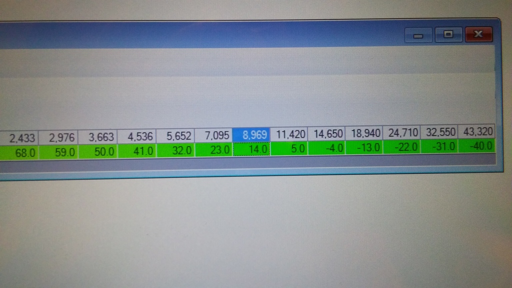
Well i assume its #1 as thats how i hooked it up today. I assume its hooked up right cause with the switch armed my IATS are reading -17. I used a 22k ohm resistor. Here are my 3 tables and what i find weird is the IAT-RPM table jumps from -4 to 14 where as the other tables have a -13 and a +5 to choose from. When i tried to use -4 the eng light came on and since +5 isnt visible on the one table i had no choice but to use +14 degrees. I read in an earlier post by tmenees2 who also has an LFX engine that he had to use a positive temp or he got a eng light. Beeing that is the case and i want to try my first pass with 5 degrees pulled do i only have to put that in the 14 degree column or that column and all temps below that as well? Here are screen shots of the tables i am talking about.


Last edited by bensrat; Nov 14, 2015 at 05:20 PM.
Teching In
Joined: Dec 2012
Posts: 25
Likes: 0
From: Florida
Show pictures less zoomed in, so I can see what you're working with... particularly the name of the table. And show a picture of the main spark screen, that shows all the available spark tables.
What kind of vehicle are you working on?
What kind of vehicle are you working on?
Teching In
Joined: Nov 2015
Posts: 13
Likes: 0
From: Tampa area
2012 Camaro RS LFX motor...same engine u helped tmenees2 in the caddy do last year. I will get some new pics posted for u. Really appreciate the help! Guess I should ask, if my IAT reading is -17 does that have to match my IAT in the chart or I can use any IAT from the chart as long as its not more negative in temp then -17?
These are the same table names (except the numbers are for my car)as the original post on page 1. I will repost mine again after work tonight.
These are the same table names (except the numbers are for my car)as the original post on page 1. I will repost mine again after work tonight.
Last edited by bensrat; Nov 16, 2015 at 03:16 PM.
Teching In
Joined: Dec 2012
Posts: 25
Likes: 0
From: Florida
I'm not familiar with there being an issue with using any temperature, but that's not to say there isn't one I'm unaware of. The only thing I know for sure is no good is to use temperatures at the end of the range (-40 or +260), etc. I know you would want to be at least say 20 degrees away from the ends, to prevent the PCM from failing the sensor and ignoring it.
I'm not sure what you're talking about with -4 and 14, or what that top table is in the picture. I need more details or less zoomed pictures of what you're doing. When I pull up a 2012 3.6 V6 Auto Camaro, I don't see much like that. I just see an IAT Spark Retard Table, and four multiplier tables to that.
The breakpoints on the IAT table go from -40 to +248 IAT temps.
Teching In
Joined: Dec 2012
Posts: 25
Likes: 0
From: Florida
Sorry, just saw the pictures you uploaded. But again, you cut off the name of the table at the top of each pic. That's alright though, as I downloaded the 2012 Camaro V6 Auto tune to look at. What exactly is your question?
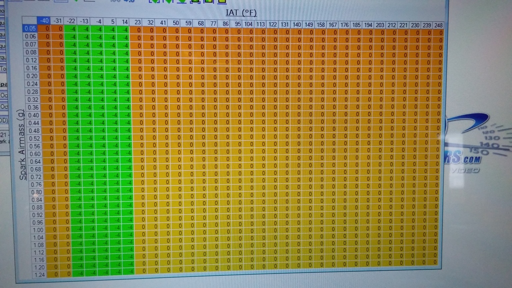
Don't screw with the IAT sensor curve table. That table just describes how the computer interprets the readings from the IAT sensor.
The other two are just the IAT retard table, and probably a multiplier table. What you need to know here is that you can't multiply anything by zero and get any answer other than zero. The table being zero'd out basically means that there will be no timing retard, even if you put any in the the IAT Spark Retard table. You would enable spark retard by making the multiplier 1.0 in the temperature areas where you want timing to be pulled... for example, 14 degrees and below.
The IAT Spark Retard table itself is also zero'd out, which is really strange. Not sure I understand why the factory wouldn't retard timing with increased IAT's, unless they are over-relying on knock sensors.
I would focus on the area between -4 and -22 degrees of IAT, and put your retard in that area. You could choose not to add the retard at low RPM, such as idle. But it's kind of nice to flip the master nitrous arm switch and hear a noticeable change in idle when you do. It's kind of an audible confirmation that the retard is working.
In any scenario, you will want to idle the car, flip the master arm switch on, and datalog Spark Advance and IAT Spark Advance/Retard. As soon as you flip the master arm switch on, you want to see the timing instantly drop by X degrees, and see the IAT retard PID rise by X degrees. At idle, timing is bouncing all over the place anyway. It may be easier to rev the motor to 2500 and then flip the master arm switch. Timing will be steady at that point, and the timing retard will be noticeable and clear.
Teching In
Joined: Nov 2015
Posts: 13
Likes: 0
From: Tampa area
Sorry if I wasn't clear. If you look at charts I labled 1 and 2 you will see IAT #5, but when you look at chart 3 there is no IAT #5. That is why I was going to use #14 as that appears on all 3 charts. I would have used a negative number like you suggested but when I tried #-4 the eng light came on. My other question was does the resistance need to be close to the IAT used or is it OK for it to be much higher. As I mentioned, I am using a 22k ohm resistor which gave me #-17 IAT. I have to wonder how would the car know to use a column less in IAT's then what it actually reads. Basically, if the car thinks its -17 iat why would it look at my warmer 14 degree IAT to pull timing? Post #75 u will see he had the same issue til he used a positive IAT.
Last edited by bensrat; Nov 17, 2015 at 05:16 AM.
LS1 Tech Stories
The Best V8 Stories One Small Block at Time

Top 10 Greatest Cadillac V Series Performance Models Ever, Ranked
Pouria Savadkouei
Top 10 Most Powerful Chevy Trucks Ever Made!

Hennessey's New Supercharged Silverado ZR2 Has 700 HP
Verdad Gallardo
Coachbuilt N2A Anteros Is an LS2-Powered C6 Corvette In Italian Clothes
Verdad Gallardo
Awesome K5 Blazer Restomod Comes With C7 Corvette Power
Verdad Gallardo
10 Camaros You Should Never Buy

10 LS Engine Myths That Refuse to Die
Verdad Gallardo
Five Reasons the Camaro Was the Most Pivotal Player in the Pony Car Wars 2.0
Brett Foote
10 Reasons the LS7 Is GM's Most Extreme Naturally Aspirated V8 Engine Ever
Verdad GallardoTeching In
Joined: Dec 2012
Posts: 25
Likes: 0
From: Florida
The Missing 5 degree breakpoint is not a problem. Those tables that are missing some are missing every other row. It's just a table with half the resolution of the other tables. Altering the row just below and above where 5 degrees would be will basically surround 5, and control it. For example if your row breakpoints are 10 and 20 degrees, and you are at 15 degrees, the PCM will interpolate between the two rows nearest you. So if breakpoint 10 commanded 1 degree of timing and breakpoint 20 commanded 3 degrees of timing, then a 15 would net you 2 degrees, because it will interpolate evenly between the two breakpoints. If the number were 11 and not 15, then you would get 1.1 degrees. See?
The engine light coming on at -4 degrees is unfortunate. We don't seem to have access to the diagnostic parameter that controls that. Somewhere in the tune, where we can't see, the factory tune probably has a parameter that says if ECT is less than X, throw an ECT circuit code. And X must be set to somewhere around 0 degrees in this tune. In the last GTO I did, I used -15 or -20 for an IAT, somewhere in there anyway, and it did not throw a code. But that was a different calibration, and X might have been -36 on that tune.
Clearly, you can't throw a code or this won't work. So if you can't change X to a lower temperature, then the only choice you have is to use a higher temp. In this case, somewhere around 5 to 10 degrees would be a good choice. You'll have to be careful here though, because we don't want to ever exceed 14 degrees or you'll start dropping timing retard towards 0 as you approach 23 degrees. I would modify the IAT retard table so you pull the desired amount of nitrous timing retard at all rows 14 degrees and below. Then pick a resistor that falls as close to 7 - 10 degrees as possible. Don't get too close to 0, and don't get too close to 14.
There's a reason for this. What if the resistor gets old and changes values a little bit? Things change over time, and you don't want to be on the ragged edge here. If you're dead certain you will never drive it in cold weather, then to be safe you could modify the next row (23 degrees) as well.
You just need to find a resistor that gives you the magic number. I used a stereo **** to test for different resistances, but you could just keep trying resistors with different resistance and keep going in the right direction, writing down the results as you go. Use alligator clips to attach the resistor to ground and your relay, until you find the right resistor.
To answer your last question, I think the answer is going to be a substituted value. The way GM works, from what I've seen, is that when a sensor fails, the PCM looks back and remembers the last known good value it produced, and just keeps using it forever, until the sensor no longer is failing. So let's say your real IAT is 72 degrees, and you turn on the relay and make the computer read -17 degrees. But the threshold for turning on the check engine light and setting a code is say 0 degrees. So the PCM will see 72, remember it, then suddenly it sees -17 and reacts by throwing a code and light and then it will ignore the sensor entirely, and use the 72 degree value for the rest of the time the key is on, or until the sensor starts reading a number above failing (0 degrees) and it knows it can now trust the sensor again. In other words, if you turn off the relay, it might start using the real sensor data again. It's also possible that once the code is thrown, it will refuse to believe the sensor even if it is correct, until the key is turned off and on again.
SUBSTITUTED VALUES WILL SCREW YOU.
If you get too close to 0 or whatever the X value is that is the threshold for a failed sensor in your calibration, the computer will default back to the last known good value, like I said. In my example above, the last known good value was 72 degrees, remember? And how much timing are we retarding at 72 degrees IAT??? None. See how you can get screwed here? Imagine pulling 6 degrees on the bottle, then suddenly you have a problem with your Nitrous IAT mod, and the computer defaults back to 72 degrees and doesn't pull timing. You'll be replacing pistons.
This means you not only need to get this right, and not get too close to the sensor failure temp threshold or the area that's too warm to pull timing, but it also means you had better be darn good at wiring. No loose connections. No corrosion. No failures over time.
In my Ebay store, I have some high quality Hella brand weatherproof Bosch 5 pin relays. They are way more heavy duty than what is really required here for an IAT signal (although they're perfect for a nitrous solenoid relay, or fan, water pump, etc). But they are weatherproof, so you never have to worry about corrosion. And they come with a nice heavy duty pigtail as well...
http://www.ebay.com/itm/Hella-Weathe...e=STRK:MESE:IT
Using this relay, pin 30 would go to the PCM side of the cut signal wire. Pin 87a would go to the sensor side of the cut signal wire. Pin 87 would go to the resistor, and on to a good ground.
Pins 86 would be power and 85 is ground (for the control side of the relay). One would be supplied all the time, and the other would come from the nitrous master arm switch, depending on how you wired it... power or ground side switched.
You would want to make darn sure that resistor was well connected to the middle of that wire between pin 87 and ground. A safe bet here might be to use thin non-insulated metal butt connectors, then heat the butt connectors up and flow some solder into them, and then use marine grade heat shrink (the type with the sealant that oozes out when you heat the shrink up). Also put the resistor some place where it can't fatigue over time, and break. Or put it inside some protective sleeve of some sort. Make this whole thing heavy duty, because you do not want it breaking over time when you're no longer paying attention to it!
One last thing. Regularly test the timing, to see if the IAT retard continues to work. And if it retards timing in the idle section of the tune, or low RPMs or whatever, listen for an audible change in motor tone. 5 degrees would be enough to change the pitch of the engine. Oh, and make sure you set all the multiplier tables to 1.00 in the areas of the tables where you need this to work. All multiplier tables must be enabled (set to 1.0) for this to work right. Datalog, and make sure you see the IAT retard PID show -5 degrees or whatever, when the master arm switch is turned on.
Teching In
Joined: Nov 2015
Posts: 13
Likes: 0
From: Tampa area
Thanks for reply again!! I made a test run this morning just to see if I am on the right track with a very small shot. I do plan to change the resistor out to something closer to the value i will actually be using. I think 14 to -17 is too big of an interpolation. I didnt see any KR come on which is good. I dont know if its an interpolation thing, but when i compared the log to a NA pass using various RPM points it didn't pull 4 degrees across the board as i programmed in the chart. Looks like it pulled 3-4, not just 4. Do you think that is because of my wide interpolation i am currently using.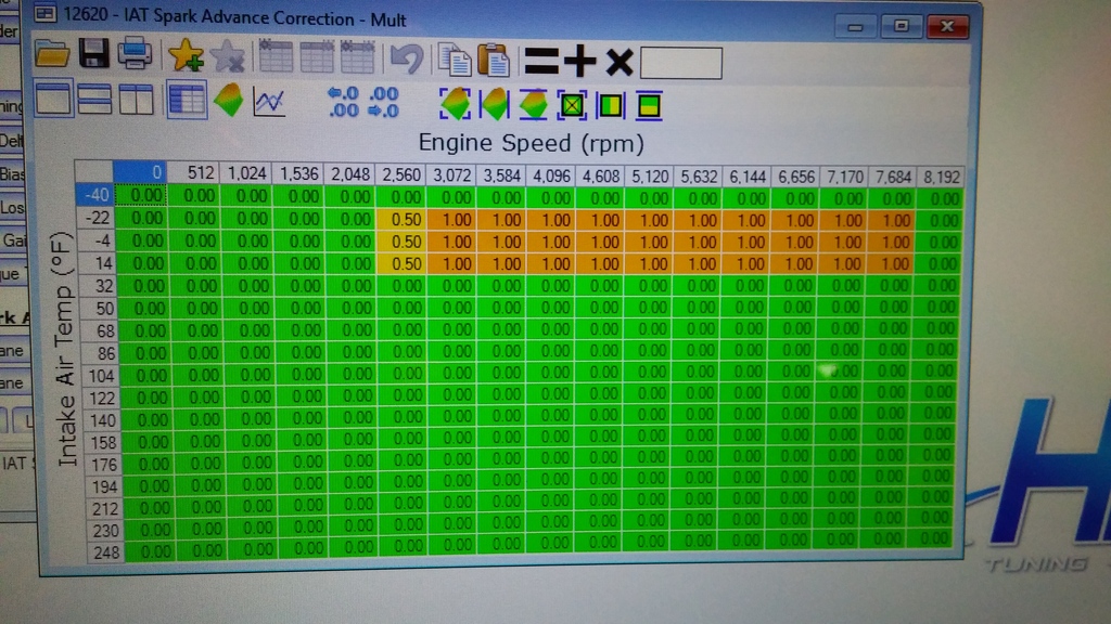


Teching In
Joined: Dec 2012
Posts: 25
Likes: 0
From: Florida
Thanks for reply again!! I made a test run this morning just to see if I am on the right track with a very small shot. I do plan to change the resistor out to something closer to the value i will actually be using. I think 14 to -17 is too big of an interpolation. I didnt see any KR come on which is good. I dont know if its an interpolation thing, but when i compared the log to a NA pass using various RPM points it didn't pull 4 degrees across the board as i programmed in the chart. Looks like it pulled 3-4, not just 4. Do you think that is because of my wide interpolation i am currently using.

You really should only have to turn the master arm switch on. And log IAT retard as well as spark Advance. It should pull pretty much exactly what you commanded. If it's 3.9 instead of 4.0, I wouldn't lose any sleep. But the IAT retard PID should show 4.0.
Also make sure the precision on your maps is set to 2 digits to see if any errors are coming from the commanded map.
Teching In
Joined: Nov 2015
Posts: 13
Likes: 0
From: Tampa area
OK, Thanks...i am picking up some more resistors today and i will replace the one i have now. I will target -4 thru 5 degrees so its a much smaller interpolation. If i use 2 resistors, should they be done in series or parallel? Does it matter?
Teching In
Joined: Nov 2015
Posts: 13
Likes: 0
From: Tampa area
OK, thanks...according to wikipedia The lowest temperature ever recorded in Tampa was 18 �F (−8 �C) on December 13, 1962, so i think using (+5 to +14) should be fine. IF it ever gets that cold i will change the tune.
Last edited by bensrat; Nov 18, 2015 at 02:09 PM.

Teching In
Joined: Aug 2013
Posts: 16
Likes: 0
From: Savannah, Ga
I want to do this to my ls1 but my base table only reads to 14F. Is there away to make it work still? Also the iat calibration table doesn't show what ohms need to be met it only gives a percentage. I apologize for not being very clear on this not sure how else to explain.
Teching In
Joined: Nov 2015
Posts: 13
Likes: 0
From: Tampa area
Yes, just use a resistor that correlates with 14 degrees. I am using a resistor that shows I am at 10 degrees when armed. Temps here in central Florida don't get that cold so for me 10 works fine. As long as you don't drive your car in 14degree weather you can use it.
Teching In
Joined: Dec 2012
Posts: 25
Likes: 0
From: Florida
I want to do this to my ls1 but my base table only reads to 14F. Is there away to make it work still? Also the iat calibration table doesn't show what ohms need to be met it only gives a percentage. I apologize for not being very clear on this not sure how else to explain.
If your table does bottom out at 14, you'll need to set your IAT trigger higher than that by 10 or 20 degrees, and then pick a resistor that causes that reading. I covered this in my earlier writeup.