


My nitrous install thread...!
I figured it out. I guess I need to learn to read better. I understand what your going to do with the Single Stage Nitrous Board, but how will you utilize the Big Dog Fuse Block and Single Relay? What all are you going to wire up to those two?

Thread Starter
TECH Apprentice
iTrader: (4)
Joined: Jan 2006
Posts: 374
Likes: 1
From: Rogersville, MO
The old new in box nitrous outlet purge solenoid I had did not match the new fuel and nitrous solenoids I got from nitrous outlet. After contacting Brandon he sent me a new sticker out. Here is the before and after.


I've been busy the past few days with a plug and wire change and tune for a local gto owner and this will probably take up my free time for the rest of the week so there will probably not be any progress made. My next goal is to get the wires soldered on the microedge to extend the harness, and work on getting the glovebox board completed and painted. Until I get the drivetrain back in the car that is about as far as I can take it.


I've been busy the past few days with a plug and wire change and tune for a local gto owner and this will probably take up my free time for the rest of the week so there will probably not be any progress made. My next goal is to get the wires soldered on the microedge to extend the harness, and work on getting the glovebox board completed and painted. Until I get the drivetrain back in the car that is about as far as I can take it.
Thread Starter
TECH Apprentice
iTrader: (4)
Joined: Jan 2006
Posts: 374
Likes: 1
From: Rogersville, MO
I will keep this thread updated as I go.
Looking really nice, very similar to what I plan to do. I'm cutting out the back of my glove box though so I can remove the glovebox anytime for ease of wiring (I'll fab up a piece of sheet aluminum to mount everything on). Then I'm taking out my passenger airbag to mount my NCC-001 nitrous controller in and I'll cut off the face of the airbag and find a way to mount it over it for that "stock" look.
Ok, I looked on Leash's website and I see you have the Big Dog Fuse Block, but the Single Stage Nitrous Board on their website looks different than the one you have. Did you opt for a different one? Still not sure what the third piece from Leash that you have is.
I am also going to do a common ground on the bottom of the panel as well as another area to try to eliminate clutter.
I just hope everything turns out as it is planned in my head.
Thanks, makes more sense now. I'm trying to visualize it in my head too, but since I've never done any extensive wiring, it's kind of hard to do. The fuse block is needed for basically everything on the switch panel, so instead of using the fuse box by the drivers side door or under the hood you can run everything off this fuse block, which is much cleaner. Very nice. For the purge, you can run that off the nitrous board because it has a spot for it, right? Too bad that nitrous board doesn't have more ports on it for other accessories, but I guess that's what the other pieces are for. I think this is going to be the cleanest install I've ever seen.
Thread Starter
TECH Apprentice
iTrader: (4)
Joined: Jan 2006
Posts: 374
Likes: 1
From: Rogersville, MO
Thanks, makes more sense now. I'm trying to visualize it in my head too, but since I've never done any extensive wiring, it's kind of hard to do. The fuse block is needed for basically everything on the switch panel, so instead of using the fuse box by the drivers side door or under the hood you can run everything off this fuse block, which is much cleaner. Very nice. For the purge, you can run that off the nitrous board because it has a spot for it, right? Too bad that nitrous board doesn't have more ports on it for other accessories, but I guess that's what the other pieces are for. I think this is going to be the cleanest install I've ever seen.
You know, you aren't that far from me and there is a track about 10 miles from my house. Maybe when you get everything done you should come down lol.
I will do that. I'll bring along a few turbo guys too. Maybe we can beat up on them a little.
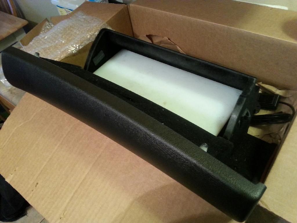
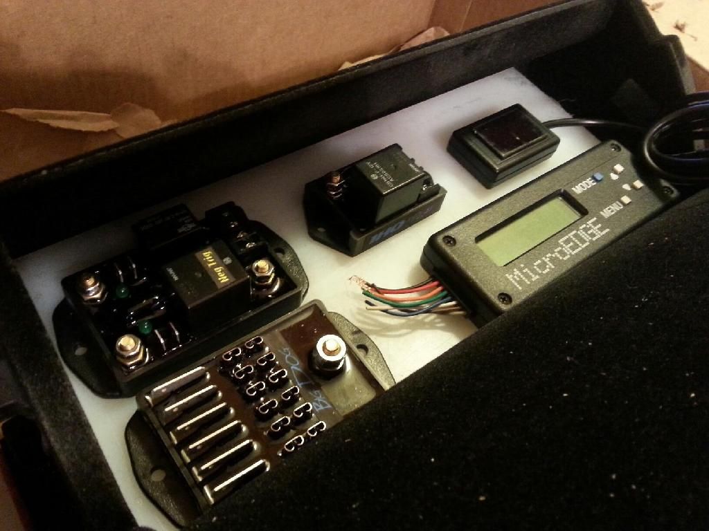
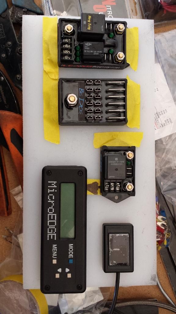
Here is the idea for the electronics. After mocking the glovebox up in the car with my panel I am going to change the layout slightly but this is the basic concept. I am actually going to be able to angle the 2 main leash boards on the left hand side.
I am going to get holes drilled so I can run the wires straight through the board then I am painting it satin black.
I am going to get holes drilled so I can run the wires straight through the board then I am painting it satin black.


Thread Starter
TECH Apprentice
iTrader: (4)
Joined: Jan 2006
Posts: 374
Likes: 1
From: Rogersville, MO
LS1 Tech Stories
The Best V8 Stories One Small Block at Time

Topdon ONE vs. Artidiag 800 BT2: Which is the Diagnostic Tablet For You?
Pouria Savadkouei
Gas Monkey Built a 6-Wheel Ferrari Testarossa With a Corvette LT4 Engine
Verdad Gallardo
7 Most Reliable High-Performance Engines GM Has Ever Built
Verdad Gallardo
Amazing '71 Camaro Restomod Is Modern Muscle Car Under the Skin
Verdad Gallardo
6 Common C5 Corvette Failures and What's Involved In Repairing Them
Pouria Savadkouei
Retro Modern Bandit Pontiac Trans AM Comes With Burt Reynolds' Autograph
Verdad Gallardo
Top 10 Greatest Cadillac V Series Performance Models Ever, Ranked
Pouria Savadkouei
Top 10 Most Powerful Chevy Trucks Ever Made!

Hennessey's New Supercharged Silverado ZR2 Has 700 HP
Verdad Gallardo Thread Starter
TECH Apprentice
iTrader: (4)
Joined: Jan 2006
Posts: 374
Likes: 1
From: Rogersville, MO
I made some decent progress today.
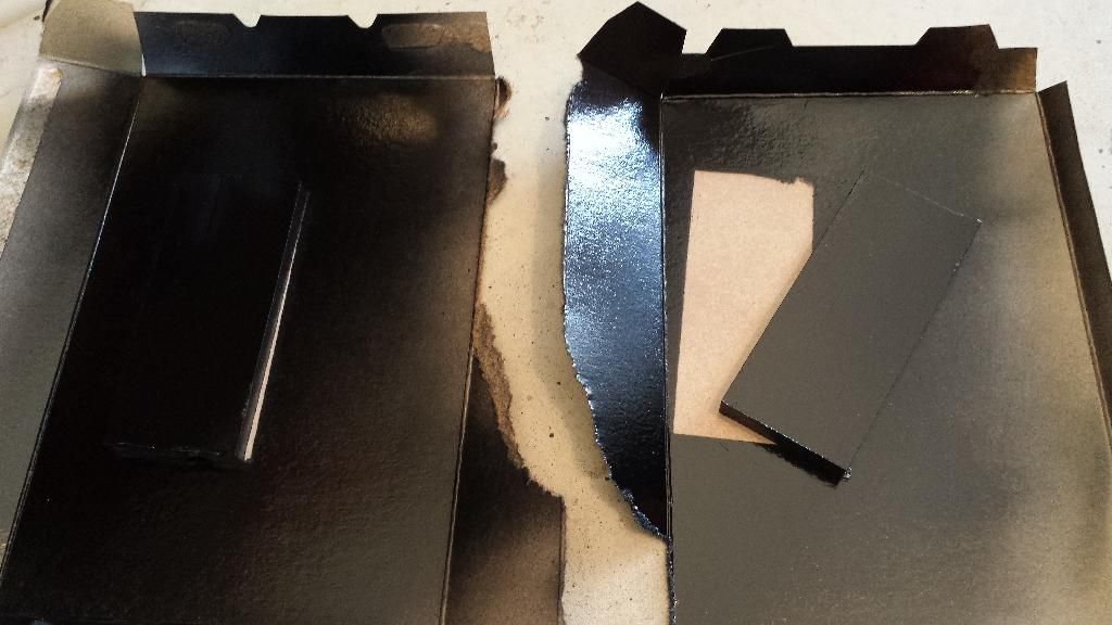
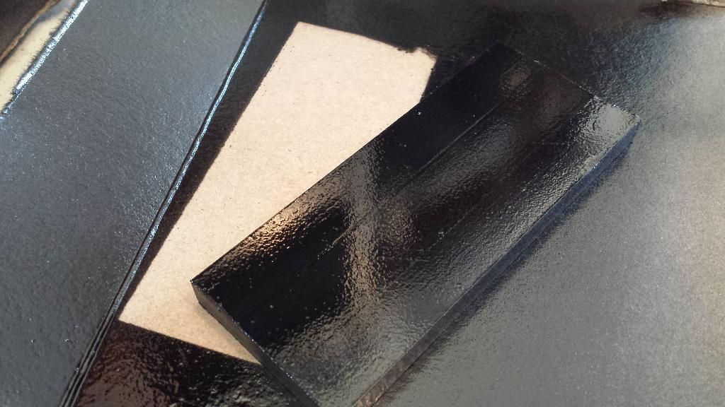
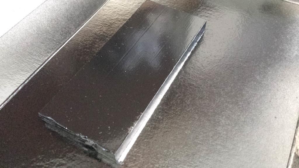
First I attempted to paint a few sample pieces of the UHMW plastic material that I am using for the glovebox board. I used a scotchbrite pad to rough the surface up and then wiped them down with some prep cleaner. I did one with krylon fusion satin only, and the other I did with satin and clear. There is some dirt in the paint but I was only trying to figure out of the uhmw would hold paint and it does.
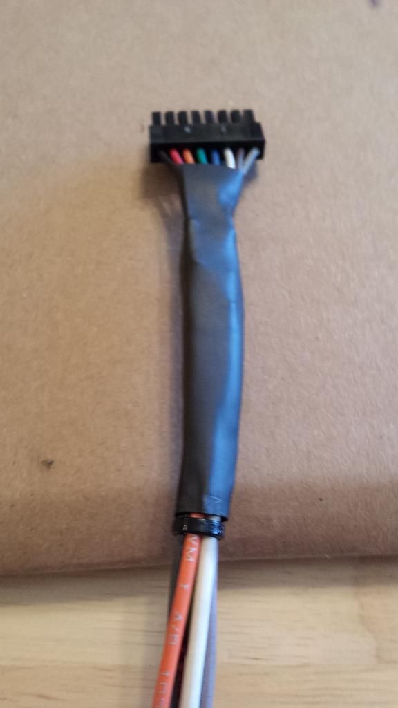
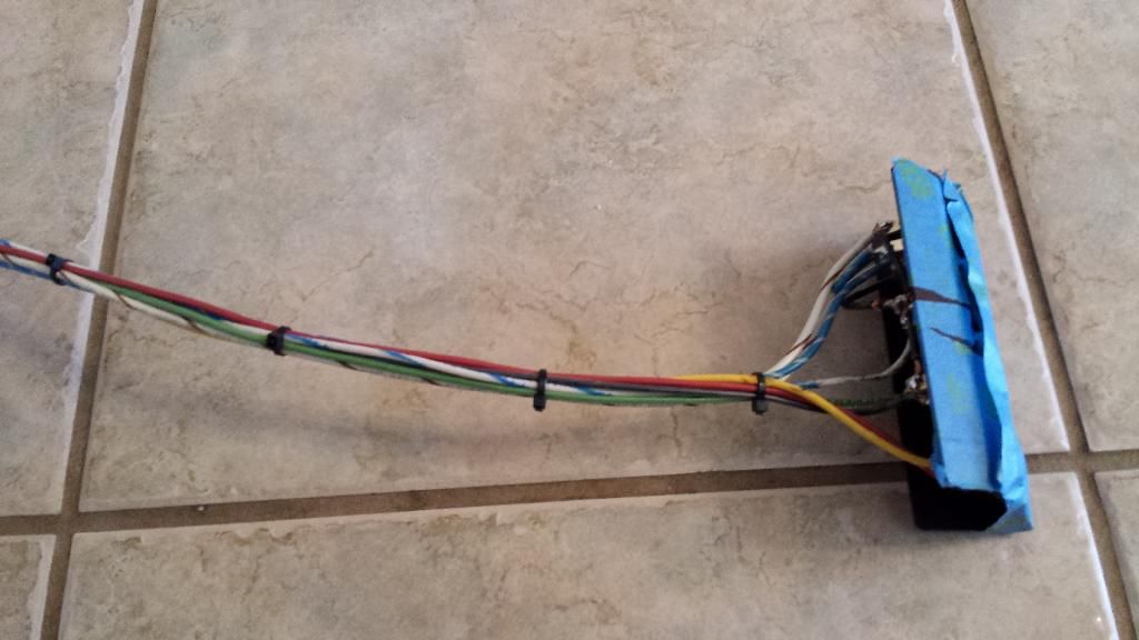
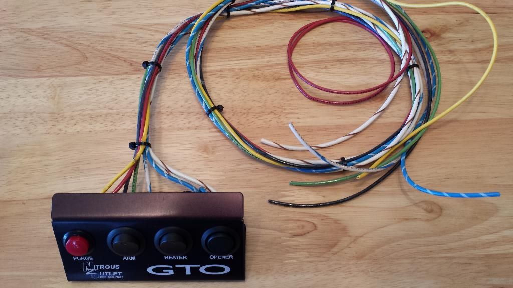
I then made the harness for the Microedge. Notice I matched the colors on the original wires.
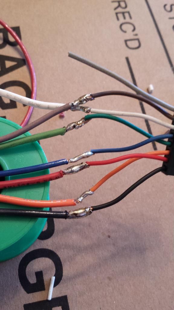
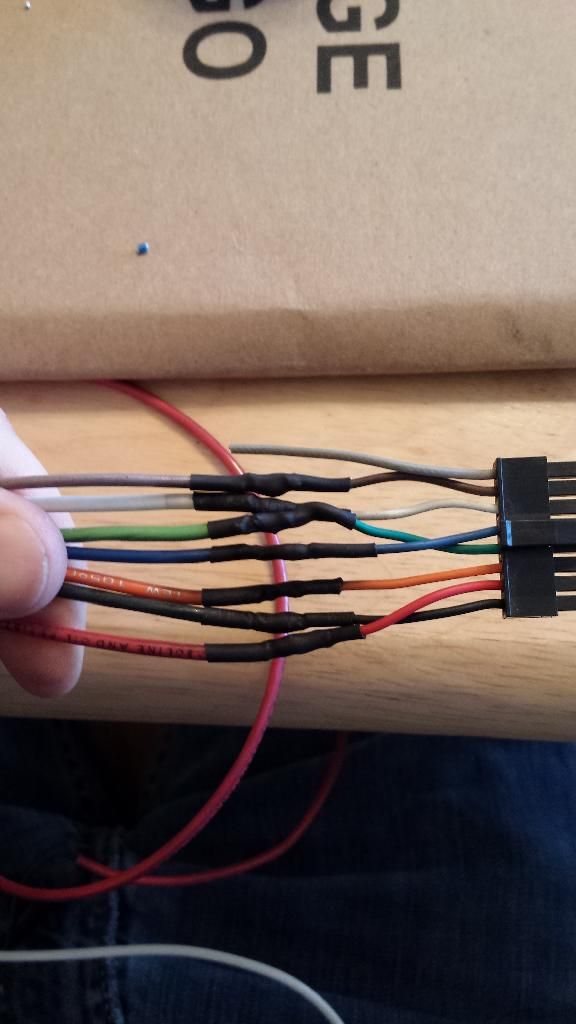
I then decided to tackle the tedious job of the wiring harness for the GTO switch panel. I opted to solder all the connections rather than use the spade terminals.
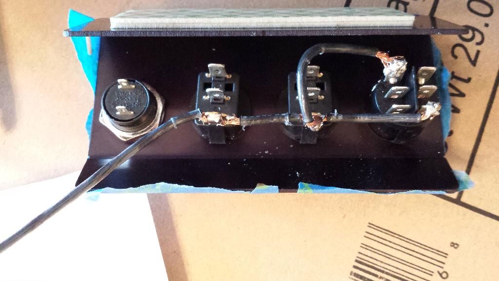
Soon after this picture was taken I began to hate my life.
I then attempted a few mock ups in the glovebox.
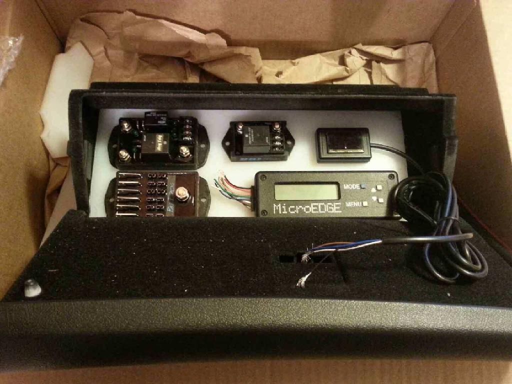
Decided that the angle was no go. This is the layout I plan to use.
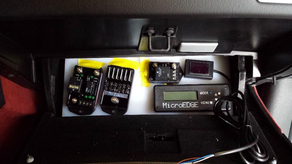
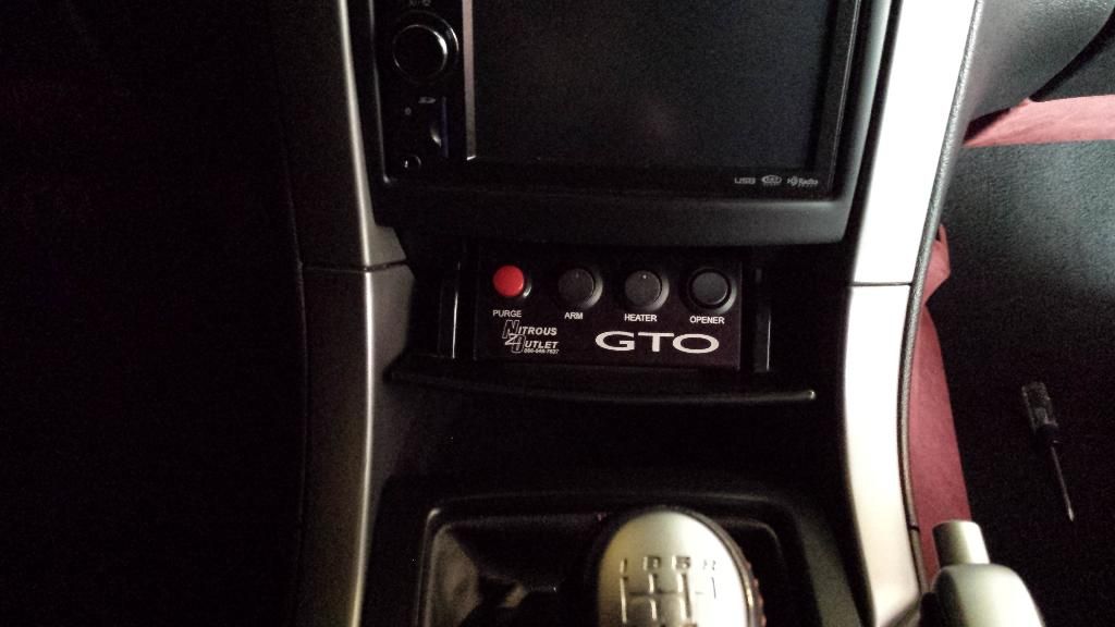
Then I attempted to fit the panel in the car.
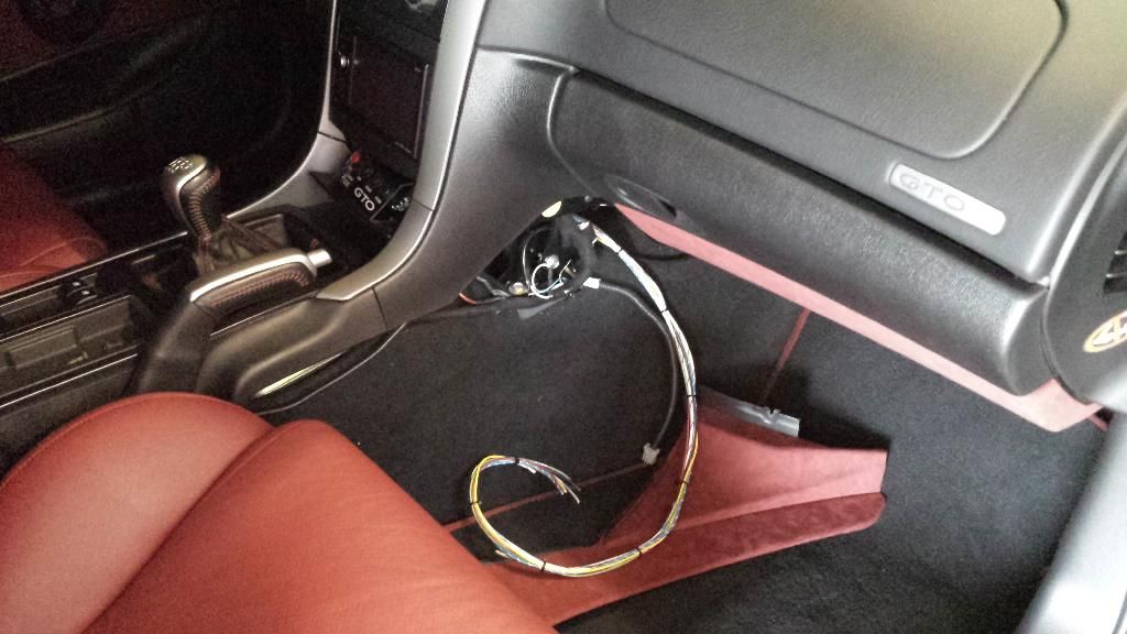
Initially it wouldn't work so I ended up pulling the panel out and increasing the bends quite a bit to make it fold up and clear. Now it is installed with the double sided tape and is there to stay.
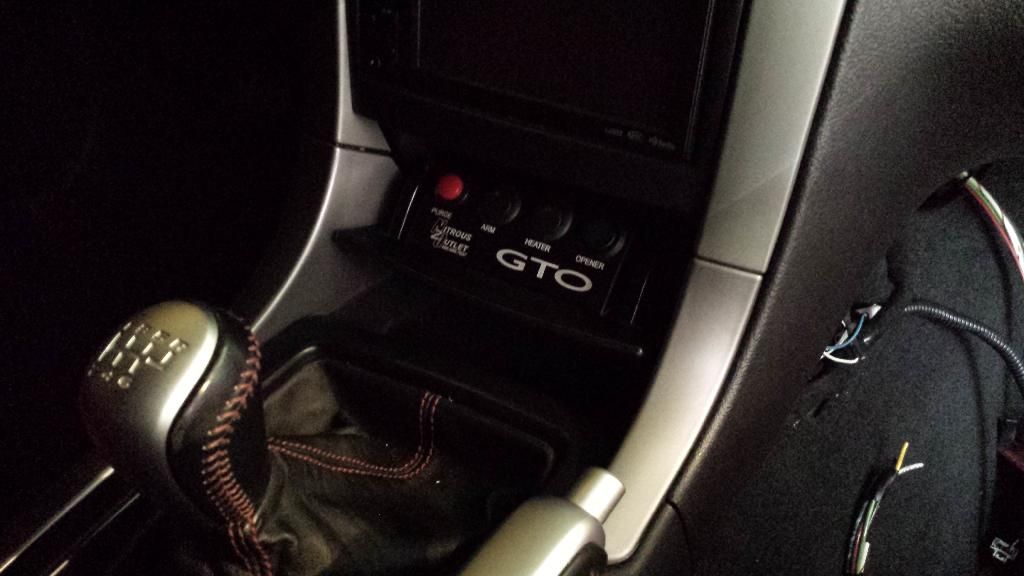
Door still shuts.
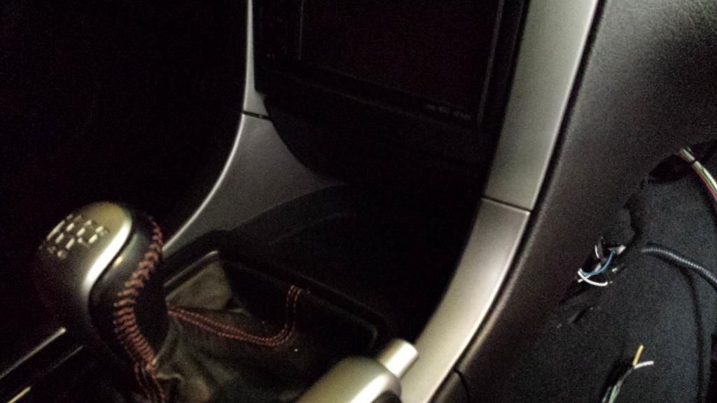
Another view.
I also made this wiring list and plan to draw up a schematic sometime this week.
First I attempted to paint a few sample pieces of the UHMW plastic material that I am using for the glovebox board. I used a scotchbrite pad to rough the surface up and then wiped them down with some prep cleaner. I did one with krylon fusion satin only, and the other I did with satin and clear. There is some dirt in the paint but I was only trying to figure out of the uhmw would hold paint and it does.


I then made the harness for the Microedge. Notice I matched the colors on the original wires.


I then decided to tackle the tedious job of the wiring harness for the GTO switch panel. I opted to solder all the connections rather than use the spade terminals.

Soon after this picture was taken I began to hate my life.


I then attempted a few mock ups in the glovebox.

Decided that the angle was no go. This is the layout I plan to use.

Then I attempted to fit the panel in the car.

Initially it wouldn't work so I ended up pulling the panel out and increasing the bends quite a bit to make it fold up and clear. Now it is installed with the double sided tape and is there to stay.

Door still shuts.

Another view.

I also made this wiring list and plan to draw up a schematic sometime this week.
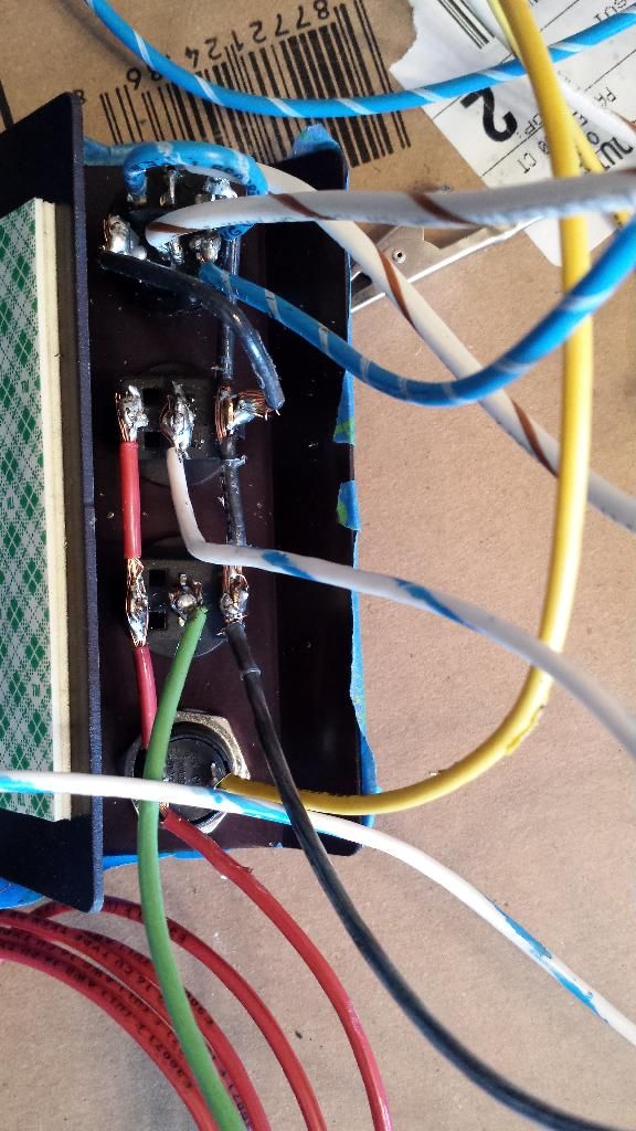
Wiring for switch panel:
Red = Main Power (to glovebox fuse block)
Black = Main Ground
Blue/ White Stripe = Bottle Opener Main Power (to glovebox fuse block)
White/ Brown Stripe = Bottle Opener (In Trunk) x 2
Light Green = Arm (to microedge in glovebox)
Yellow = Purge (to relay in glovebox)
White/ Blue Stripe = Power for heater (to pressure switch in trunk)
Wiring for Microedge:
Red = Main Power (to fuse block in glovebox)
Black = Main Ground
Orange = Wideband
Light Green = Arm (to switch panel)
Blue = TPS
White = RPM
Brown = Stage 1 Control (to relay in glovebox)
Leash Nitrous Controller:
Red = Main Power (from battery)
Black = Main Ground
Brown = Stage 1 Control (from microedge)
Yellow = Purge (from switch panel)
Blue = Nitrous & fuel (underhood)
Dark Green = Purge (underhood)
Leash HD relay:
Red = Main Power (from battery)
Red = Heater (to trunk)
Black = Ground
White/ Blue Stripe (from pressure switch in trunk)
Dynotune Digital Gauge:
Brown = Main Power (from glovebox fuse panel) x2
Blue = Ground
AEM Wideband:
Red = Main Power (from glovebox fuse panel)
Black = Ground
White = 0-5v output (to Microedge & output for hp tuners)
Relay in glovebox for Fuseblock:
Green = To Fuse Panel
Black = Main Power (from battery)
White = Ground
Red = Trigger (cigarette lighter)
Leash Fuse Block:
Green = From Relay
Red = To Wideband
Brown = To Dynotune Gauge
Red = To Microedge
Red = To Switchpanel
Blue/ White Stripe = To Switchpanel (remote opener)

Thread Starter
TECH Apprentice
iTrader: (4)
Joined: Jan 2006
Posts: 374
Likes: 1
From: Rogersville, MO
Thanks that's the goal.
That's what I do guy.
Nitrous pressure gauge.
Nitrous pressure gauge.
Gottcha. I just amazes me how you can come up with all of this and think it out like you have. I know you've done it before, but damn, you've got this **** down to a science. You need to start up a side business doing this. I may have to pay you to hook me up.
Thread Starter
TECH Apprentice
iTrader: (4)
Joined: Jan 2006
Posts: 374
Likes: 1
From: Rogersville, MO
Gottcha. I just amazes me how you can come up with all of this and think it out like you have. I know you've done it before, but damn, you've got this **** down to a science. You need to start up a side business doing this. I may have to pay you to hook me up.
I wish I would have had room in the glovebox for the dual relay setup from leash...unfortunately I am going to have to mount the relay for the fused distribution block on the bottom of my glovebox panel.
I am also keeping this setup in a way where I can remove everything from the car if needed without cutting wires.
Thread Starter
TECH Apprentice
iTrader: (4)
Joined: Jan 2006
Posts: 374
Likes: 1
From: Rogersville, MO
http://www.ls1gto.com/forums/showthread.php?t=609889
There is my sik rear end build I'm ***** deep in.
There is my sik rear end build I'm ***** deep in.


