When you click on links to various merchants on this site and make a purchase, this can result in this site earning a commission. Affiliate programs and affiliations include, but are not limited to, the eBay Partner Network.
I just went through the process of testing this unit and I'd like to share some findings which could help someone avoid some headaches. The following applies to a single stage setup.
#1. Verify that your TB is opening at 90 degrees when at WOT. If not, adjust the cable.
#2. Test the voltage at the TPS using a multimeter. These can be had for cheap at Harbor Freight. The TPS variable voltage wire is the blue wire leading into the connector. This is the same blue wire that leads to Pin 24 on the Red ECM which is TPS Sensor Signal Pin "C". This is the wire you can use for your TPS signal that gets hooked into the blue/white wire on the NOS Mini, or "CH 1 signal".
For any wiring tapping, if you aren't going to solder the connection, at least use a 3M 951 T-Tap. Do not use those quick splice tap.
Your voltage at the TPS should be around 4.5-4.6 at WOT.
#3.
Start with these settings for CH1
F - 15 (Solenoid Frequency 15 hz recommended)
C - 04 (RPM signal Set-up - 4 cylinder)
P - 00 (Ramp Pause Mode - ramp is reset when deactivated)
1 - 30 (Activation RPM - 3000)
2 - 68 (De-activation RPM - 6800)
3 - 00 (Delay time - 0 sec)
4 - 40 (Start % - 40%)
5 - 10 (Ramp time - 1.0 seconds)
6 - 99 (End % - 99%)
7 - 00 (Control output delay - 0%)
8 - 02 (TPAS mode - 02 = TPS Signal)
9 - 45 (TPS Setting - auto learn by going WOT in setup)
If the voltage isn't reaching 4.5-4.6 when you press the pedal to wot, something isn't hooked up correctly. Make sure you've grounded both wires coming out of the nos mini to separate ground points.
For CH 2, if you aren't going to use it set it up for:
F - 15 (Solenoid Frequency 15 hz recommended)
C - 04 (RPM signal Set-up - 4 cylinder)
P - 00 (Ramp Pause Mode - ramp is reset when deactivated)
1 - 99 (Activation RPM - 9999)
2 - 68 (De-activation RPM - 6800)
3 - 00 (Delay time - 0 sec)
4 - 40 (Start % - 40%)
5 - 10 (Ramp time - 1.0 seconds)
6 - 99 (End % - 99%)
7 - 00 (Control output delay - 0%)
8 - 01 (TPAS)
9 - 45 (TPS Setting - auto learn by going WOT in setup)
If you have nothing connected to CH2 and your getting a "r 2" readout,
set your activation RPM on channel 2 to be 99 (9999 rpms) and set TPAS in step 8 to be 01. Now you will see that the read out says "r r".
With key in run position with engine off, when you press the pedal to the floor, it should change from "r r" to "1 r" and then go back to "r r" when you release the pedal.
4. If your solenoids aren't clicking, it's more than likely because you haven't bypassed the FPSS. Connect the wire leading to the FPSS to a good ground point. When you go back to use the FPSS, verify that it is correct using a pressure gauge.
5. To test if everything is working properly:
-set the RPM activation for CH1 to 00 (don't forget to change it back to 3000 rpms after testing). The solenoids will NOT click with the car turned to just the accessory on position unless you set the RPM activation to be 00. If it's set at 30 (3000 rpms) you won't hear the solenoids click with the car in the accessory on position. Do not start the car to test it, always test with the engine off.
-bypass the FPSS
-with the engine off and the car in run mode, press the pedal to the floor. You should see on the nos mini display it change from "r r" to "1 r". You should also hear the solenoids click. If not, something is wiring incorrectly.
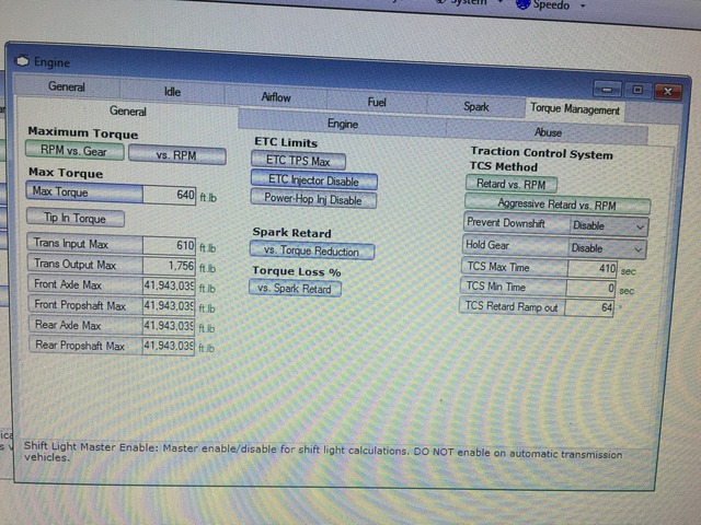
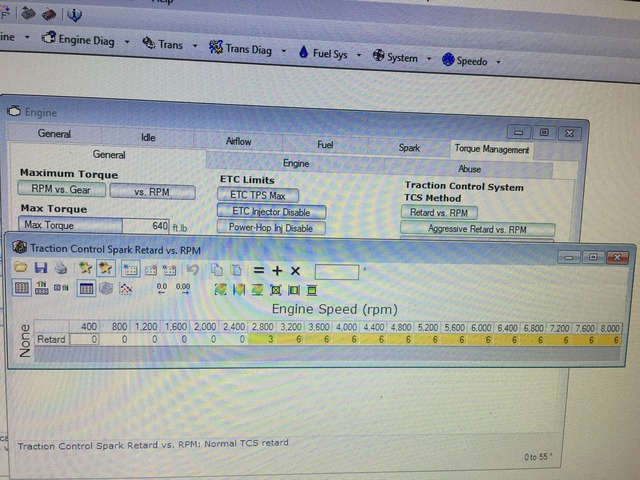
6. Attached are my wiring diagrams. One if you are using an LNC-2000, and another if you are using HP tuners to pull timing by the TCS. Pulling timing by the TCS requires a 2002 *156 operating system if using HP tuners. My car was a 2000, so I flashed the ECM to a 2002. If using EFI live, I think you can get away with not having to flash to 2002. The reason why you need the newer OS is because of the TCS tables. If pulling 6 degrees of timing, the tables would look like this:
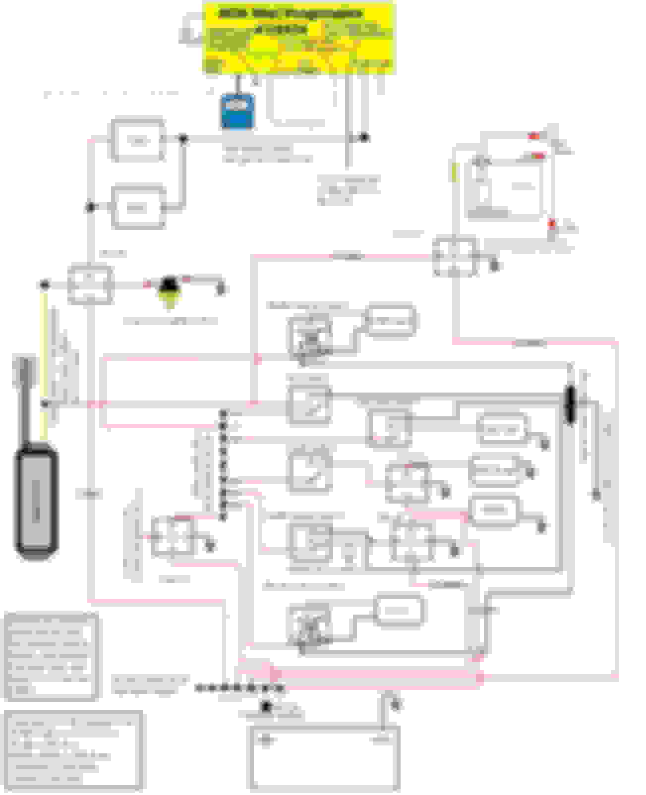
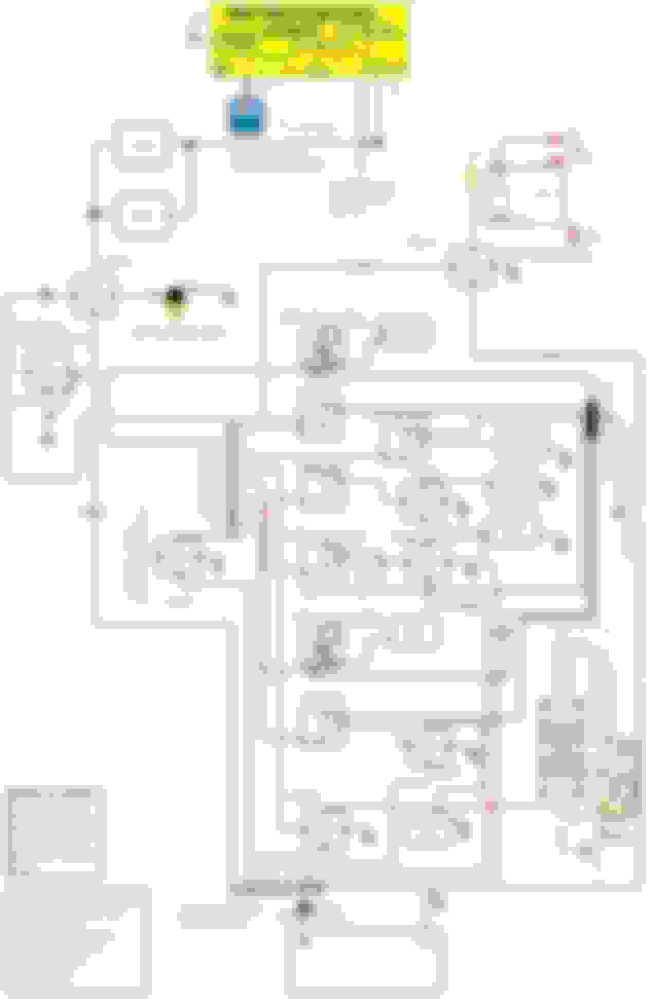
7. Diagrams
Nos mini and LNC 2000
Nos mini and TCS
Last edited by 5.7stroker; Apr 22, 2018 at 09:41 AM.
I would like to add the use of a "kick-back" diode to your circuit.
These are used to return the solenoid electromagnet current to ground when the field collapse occurs.
The speed can then be increased if necessary, 15-30 Hz, for better results.
I would "spec" a 39-46 volt Zener 1/2 Watt.
This will help with valve seat life.
I'm having problems with getting my controller to go into program mode. With key on not started. it shows r r, When I press both toggles the r r will blink, sometimes is may flash a 0.00. but it will never show PRO. I have moved my grounds around thinking that was the problem. but I have the same result. Any suggestions?
I'm having problems with getting my controller to go into program mode. With key on not started. it shows r r, When I press both toggles the r r will blink, sometimes is may flash a 0.00. but it will never show PRO. I have moved my grounds around thinking that was the problem. but I have the same result. Any suggestions?
Try disconnecting the hand held part and make sure the connection is clean. It sounds like the hand held isn't communicating with the box.
Sounds like it. Did you purchase the Mini from us?
Pretty sure I did not. But This thing is probably about 5 years old. I used it like 3 times and then took it off the car and its been sitting bagged up on the shelf for the last 4-5 years. I decided to put it back on the car for a race this weekend. But oh well. I just wanted to make sure it wasn't something I was overlooking. Thanks for your help.
Good info on this thread. Hoping to bring it back. I've read that a single channel on the nos mini is limited to 40 Amp draw only. What is the correct way to connect 4 solenoids to 1 channel? I know you can split the channels for the fuel and nos solenoids but not trying to do that at the moment.
6 Common C5 Corvette Failures and What's Involved In Repairing Them
Slideshow: From wobbling harmonic balancers to failed EBCMs, these are the issues that define long-term C5 ownership and what repairs typically involve.
Retro Modern Bandit Pontiac Trans AM Comes With Burt Reynolds' Autograph
Slideshow: A modern Camaro transformed into a retro icon, this limited-run "Bandit" build blends nostalgia with brute force in a way few revivals manage.
Top 10 Greatest Cadillac V Series Performance Models Ever, Ranked
Slideshow: Cadillac didn't just crash the high-performance luxury vehicle party, it showed up loud, supercharged, and occasionally a little unhinged...
Coachbuilt N2A Anteros Is an LS2-Powered C6 Corvette In Italian Clothes
Slideshow: A one-off sports car that looks like a vintage Italian exotic-but hides a C6 Corvette underneath-just sold for the price of a new mid-engine Corvette.