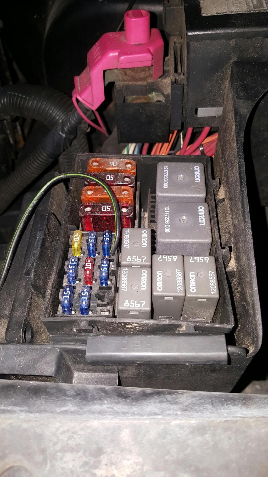
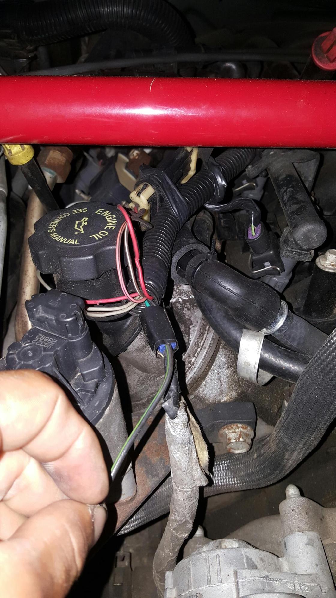
What does this wire go to?
#1
Staging Lane
Thread Starter
iTrader: (1)
Join Date: Jul 2011
Location: Houston TX
Posts: 72
Likes: 0
Received 0 Likes
on
0 Posts

Hey guys i just purchased a 99 t/a vert ws6 and just my luck the check engine light came on a few minutes after purchase(pretty sure po reset the ecm) anyway so i got a code p0650 (indicator light circuit malfunction)
so i opened the hood to see what surprises i find and i found this wire, can anyone tell me what it goes to? and how i can possibly re do this set up so it wont be rigged up so badly? also could it be that its related to that code?
see pics below


any help appreciated
#3
Staging Lane
Thread Starter
iTrader: (1)
Join Date: Jul 2011
Location: Houston TX
Posts: 72
Likes: 0
Received 0 Likes
on
0 Posts
I havent really had a chance to pay attention but the ac turns off when i turn it off manually inside the vehicle.
so the wire just goes to the AC clutch, could it be at all related to the code?
so the wire just goes to the AC clutch, could it be at all related to the code?
#4
TECH Senior Member
iTrader: (25)
That has nothing to do with a P0650 code. That is the PCM not seeing the SES Led in the circuit. Does the SES light in the cluster come on with KOEO bulb check?
On the wire, disconnect it from where they tapped the fuse. If the AC compressor stops running then there was probably an open in the circuit running from the fuse box to the AC compressor clutch and that was their way of fixing it. Are you sure the compressor stops? It appears they are bypassing the compressor relay.
On the wire, disconnect it from where they tapped the fuse. If the AC compressor stops running then there was probably an open in the circuit running from the fuse box to the AC compressor clutch and that was their way of fixing it. Are you sure the compressor stops? It appears they are bypassing the compressor relay.
#6
TECH Senior Member
iTrader: (25)
KOEO is key on engine off.
P0650
Circuit Description
A voltage is supplied directly to the Malfunction Indicator Lamp (MIL). The PCM controls the lamp by grounding the control circuit via an internal switch called a driver. The primary function of the driver is to supply the ground for the component being controlled. Each driver has a fault line which is monitored by the PCM. When the PCM is commanding a component ON, the voltage of the control circuit should be low (near 0 volts). When the PCM is commanding the control circuit to a component OFF, the voltage potential of the circuit should be high (near battery voltage). If the fault detection circuit senses a voltage other than what is expected, the fault line status will change causing the DTC to set.
Conditions for Running the DTC
Engine speed is greater than 400 RPM.
The ignition voltage is between 6.0 volts and 18.0 volts.
Conditions for Setting the DTC
The PCM detects that the commanded state of the driver and the actual state of the control circuit do not match.
The conditions are present for a minimum of 5 seconds.
Action Taken When the DTC Sets
The PCM stores DTC P0650 in memory on the second consecutive ignition cycle that the diagnostic runs and fails.
The Malfunction Indicator Lamp (MIL) will not illuminate.
The PCM records the operating conditions at the time the diagnostic fails. The first time the diagnostic fails, the PCM stores this information in the Failure Records. If the diagnostic reports a failure on the second consecutive ignition cycle, the PCM records the operating conditions at the time of the failure. The PCM writes the conditions to the Freeze Frame and updates the Failure records.
Conditions for Clearing the MIL/DTC
A History DTC will clear after forty consecutive warm-up cycles, if no failures are reported by this or any other non-emission related diagnostic.
A last test failed (Current DTC) will clear when the diagnostic runs and does not fail.
Use a scan tool in order to clear the MIL/DTC.
Diagnostic Aids
Important:
Remove any debris from the PCM connector surfaces before servicing the PCM. Inspect the PCM connector gaskets when diagnosing/replacing the PCM. Ensure that the gaskets are installed correctly. The gaskets prevent contaminate intrusion into the PCM.
For any test that requires probing the PCM or a component harness connector, use the Connector Test Adapter Kit J 35616-A. Using this kit prevents damage to the harness/component terminals. Refer to Using Connectors Test Adapters in Diagrams.
The following may cause an intermittent:
Poor connections; Refer to Intermittents and Poor Connections. See: Powertrain Management\Computers and Control Systems\Testing and Inspection\Initial Inspection and Diagnostic Overview\Diagnostic Strategies\Intermittent Conditions
Corrosion
Mis-routed harness
Rubbed through wire insulation
Broken wire inside the insulation
If the ignition feed circuit is suspected of being open, inspect for lamps on the same circuit not illuminating.
Using Freeze Frame and/or Failure Records data may aid in locating an intermittent condition. If you cannot duplicate the DTC, the information included in the Freeze Frame and/or Failure Records data can aid in determining how many miles since the DTC set. The Fail Counter and Pass Counter can also aid determining how many ignition cycles the diagnostic reported a pass and/or a fail. Operate the vehicle within the same freeze frame conditions (RPM, load, vehicle speed, temperature etc.) that you observed. This will isolate when the DTC failed. For an intermittent condition, refer to Symptoms. See: Powertrain Management\Computers and Control Systems\Testing and Inspection\Symptom Related Diagnostic Procedures
Test Description
The numbers below refer to the step numbers on the diagnostic table.
Command both the ON and the OFF states. Repeat the commands as necessary.
If you do not find trouble in the control circuit or the connection at the PCM, the PCM may be faulty. However, this is an extremely unlikely failure.


