




Inexpensive Opensource Flashing(Read is 100% working)

Thread Starter
TECH Enthusiast

Joined: Oct 2017
Posts: 567
Likes: 159

It's not US built but it's a quality product. Might be from Canada.....don't recall off hand but it wasn't China.
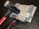
The above device is what I have written a "Guide" for if you will on how to install and use it. Any other brand/type your on your own.
Just keep in mind this requires opening the pcm up and soldering onto the pcb. It's not done over the data port.

Teching In
Joined: Sep 2018
Posts: 2
Likes: 0
https://www.usbjtag.com/zenshop/inde...products_id=11
It's not US built but it's a quality product. Might be from Canada.....don't recall off hand but it wasn't China.
The above device is what I have written a "Guide" for if you will on how to install and use it. Any other brand/type your on your own.
Just keep in mind this requires opening the pcm up and soldering onto the pcb. It's not done over the data port.
It's not US built but it's a quality product. Might be from Canada.....don't recall off hand but it wasn't China.
The above device is what I have written a "Guide" for if you will on how to install and use it. Any other brand/type your on your own.
Just keep in mind this requires opening the pcm up and soldering onto the pcb. It's not done over the data port.
Awesome thanx, i have just ordered two of them, I like to have spares.
If you ever need any testing, let me know
I have over heaps of pcms here Ls1, E38, E40, BA-FG Pcms
I have open licenced HP Tuners
Many scan tools
And heaps of other gear as well..
Always happy to help..
Thread Starter
TECH Enthusiast
Joined: Oct 2017
Posts: 567
Likes: 159
To make it easier for people who are interested in a hard wired method soldering to the pcm's pcb I've uploaded every thing to google drive. To keep this thread clear of questions you can PM me if you would like to know more. If that brings is a wave of questions on this method I may just make a new thread specifically about this but for now I'll do questions on a per-person basis.
https://drive.google.com/open?id=19d...tO6w4lnQ8S9ViL
https://drive.google.com/open?id=19d...tO6w4lnQ8S9ViL

what if you used this idea to connect a usb cord through the pins in the ecu that are listed as unused, and then just ran the usb cord into the cabin of the vehicle?
Thread Starter
TECH Enthusiast
Joined: Oct 2017
Posts: 567
Likes: 159
The next issue you MIGHT run into is interference from being in such close proximity to the other signal wires from the engine.
USB cables have a specified maximum length, once you exceed that all bet's are off. In most cases a quality cable can be several feet longer with out an issue but results may vary from one cord to the next.
But in theory what your saying would work...although drilling a hole in the pcm's case isn't the issue it's keeping the USB cable end clean and dry.
For those that have't read the instructions document, when using the BDM there is 1 wire that needs to be switched "On", it puts power to the flash chip that allows writing to it. You can read the Pcm with out this wire but it MUST be turned on to write. One of the aspects of using the PIE ZERO to do this was that you could use one of the Pie's I/O pins to handle the switching automatically. Doing it as suggested above also would require a switch be placed in the same area as the USB cable's end so you can enable write. If you leave the switch "On"....nothing bad will happen but it car won't start. You have to turn the switch"Off" and turn the ignition switch off to return the PCM to a "Normal" state. It's still totally doable but slightly inconvenient.
If someone was knowledge with Linux or specifically the Raspberry Pie and was able to write a simple program to do this I'd be more then happy to work with them to make this a viable option over Wi-Fi/BT...... talk to your friends

I wish I would of continued my education, nearly 20 years ago, in computer science 😂 this is an awesome project and I look forward to watching it’s development. I stumbled upon this thread trying to find a way to unbrick my ecu so this would be great to see come to fruition.

Registered User
Joined: Oct 2018
Posts: 1
Likes: 0
Getting pumped Been following these threads now for years I'm really looking forward to playing with this hammer when it's done. I'd love to help but have no computer skills lol I can use software and help to some degree to make xdfs files but that's about all the computer skills I got. I've started to help contribute by starting an xdf over at pcmhacking for my 2000 grand prix Gtp plan to add more os versions once I'm done the one. And Great work to everyone that has made this continue to grow. Thx for everyone's hard work.
LS1 Tech Stories
The Best V8 Stories One Small Block at Time

Gas Monkey Built a 6-Wheel Ferrari Testarossa With a Corvette LT4 Engine
Verdad Gallardo
7 Most Reliable High-Performance Engines GM Has Ever Built
Verdad Gallardo
Amazing '71 Camaro Restomod Is Modern Muscle Car Under the Skin
Verdad Gallardo
6 Common C5 Corvette Failures and What's Involved In Repairing Them
Pouria Savadkouei
Retro Modern Bandit Pontiac Trans AM Comes With Burt Reynolds' Autograph
Verdad Gallardo
Top 10 Greatest Cadillac V Series Performance Models Ever, Ranked
Pouria Savadkouei
Top 10 Most Powerful Chevy Trucks Ever Made!

Hennessey's New Supercharged Silverado ZR2 Has 700 HP
Verdad Gallardo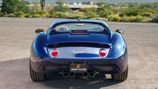
Coachbuilt N2A Anteros Is an LS2-Powered C6 Corvette In Italian Clothes
Verdad Gallardo

 Raspberry P3B + 7" Touch Screen
 Hi Pete, I just purchased a Raspberry P3 AND the 7" touch screen. (starter kit)
I would like to use this type of item to "flash, store, and edit" GM calibrations.
I will also make a "daughter" card for my uses.
There is plenty of I/O (shift light, etc) AND board mounted Broadcom Wi-Fi.
I would like to "share" my progress with LS-1 tech members
Will you, Pete, be willing to "guide" my work ?
I would like to have a product to compete with the GM-Tech-II.
Lance.
I would like to use this type of item to "flash, store, and edit" GM calibrations.
I will also make a "daughter" card for my uses.
There is plenty of I/O (shift light, etc) AND board mounted Broadcom Wi-Fi.
I would like to "share" my progress with LS-1 tech members
Will you, Pete, be willing to "guide" my work ?
I would like to have a product to compete with the GM-Tech-II.
Lance.
Thread Starter
TECH Enthusiast
Joined: Oct 2017
Posts: 567
Likes: 159
Hi Pete, I just purchased a Raspberry P3 AND the 7" touch screen. (starter kit)
I would like to use this type of item to "flash, store, and edit" GM calibrations.
I will also make a "daughter" card for my uses.
There is plenty of I/O (shift light, etc) AND board mounted Broadcom Wi-Fi.
I would like to "share" my progress with LS-1 tech members
Will you, Pete, be willing to "guide" my work ?
I would like to have a product to compete with the GM-Tech-II.
Lance.
I would like to use this type of item to "flash, store, and edit" GM calibrations.
I will also make a "daughter" card for my uses.
There is plenty of I/O (shift light, etc) AND board mounted Broadcom Wi-Fi.
I would like to "share" my progress with LS-1 tech members
Will you, Pete, be willing to "guide" my work ?
I would like to have a product to compete with the GM-Tech-II.
Lance.
Then you'd either need to get one of the existing devices working on the Pie like the Allpro or Obdlink or you'd need to create your own J1850 VPW interface and write the firmware for it.
If you were looking for an "easier" way out but it's not a portable solution there is already support for the USB BDM NT on the Pie. Not an amazing option but the flash times are only a couple of seconds VS a couple of minutes if done over the data bus.
Now let me propose an alternative to your Pie interface idea. I already have the program and interface circuit designed to use an Arduino. The program use's 6% of the storage space leaving plenty of room for adding on to the existing code. The Arduino's are also compatible with a great number of displays and can support touch screen interface although it's not going to be as "Nice" looking as the Pie it would be just as functional.
You could also use the Arduino in conjunction with the Pie but change the arduino into a transceiver to communicate with the vehicle. The existing code wouldn't take much to change it over to something more like a pass though device to talk to the vehicle.
If this is something you plan on pursing I'd suggest creating a new topic and sending me the link by PM. I'd be happy to discus this idea in greater depth openly for others to learn from but I don't really think it's an appropriate conversation to continue in this particular thread or it's going to get way off track.
TECH Fanatic


Joined: Jan 2018
Posts: 1,060
Likes: 198
The guy who did the command-line version got into a disagreement with his employer over who owns the rights to what he did, so his stuff had to be removed. However he was just getting started, so it's not a huge loss, just a bit of a set back.
I agree with Pete that we should start another thread for a Raspberry Pi version. I'll help out when I can.
On the Windows from, we are very close to having something that we can release that will read the contents of the PCM.
I agree with Pete that we should start another thread for a Raspberry Pi version. I'll help out when I can.
On the Windows from, we are very close to having something that we can release that will read the contents of the PCM.


Thread Starter
TECH Enthusiast
Joined: Oct 2017
Posts: 567
Likes: 159
Two other people have also started working on other aspects of to the Pcm Hammer over the last couple of weeks that should really help get things rolling. Let's just say this may end working on more then just the P01 and P59 pcm's......... but it's still too early to say exactly what other pcm's they are working on adding compatibility for just yet 

Registered User
Joined: Oct 2018
Posts: 1
Likes: 0
From: Boca Raton Florida
C4 1991 with obd1 ecu needs dyno tuning south florida I am looking for someone in Florida that can Dyno Tune my 1991 C4 the car has a 390 stroker, 10.5 -1 compression . runs rich needs fuel and air and timing set. Anyone know of a shop please share.
Thanks
Thanks

TECH Senior Member
Joined: Jun 2016
Posts: 22,298
Likes: 3,619
From: Central Cal.
Please don't hijack other people's threads with non-related stuff.
that actually makes me think of something. when I was looking at all the available xdf's for Tunerpro I stumbled across a file definition for the DME in my pre-obd2 '93 BMW
how does one interface with a vehicle that doesnt have a regular obd2 serial port?
how does one interface with a vehicle that doesnt have a regular obd2 serial port?
TECH Senior Member
Joined: Jun 2016
Posts: 22,298
Likes: 3,619
From: Central Cal.
Not sure you can, unless one can somehow tap directly onto the motherboard, as you would need access to all inputs/outputs. Good question!
I think the OBDII connection has spoiled us to a degree! lol
I think the OBDII connection has spoiled us to a degree! lol